email: tony@lathes.co.uk
Home   Machine Tool Archive   Machine-tools Sale & Wanted
Machine Tool Manuals   Catalogues   Belts   Books   Accessories

Bridgeport Millers
Original "Round-ram" Model

High-quality Handbooks, Parts Lists and Spares are available
for most Bridgeport machines


Bridgeport Home Page

Bridgeport Vertical Heads & Attachments

Original Bridgeport Round-ram Model

Bridgeport Accessories   

The Bridgeport Miller at Work

Vertical Attachments by Halco and Kerney & Trecker (Dalrae)

Bridgeport Table Power-feed Units   

Bridgeport Serial Numbers

Bridgeport Horizontal Stub Miller

Further Bridgeport Company History and "Building a Bridgeport"

Bridgeport Series 1 CNC Miller (based on the standard machine)

Bridgeport Larger CNC Millers (Interact, APC, BPC)

Late Edition, Series 1 Ram-head Miller Catalogue

Computer-modelled Illustration

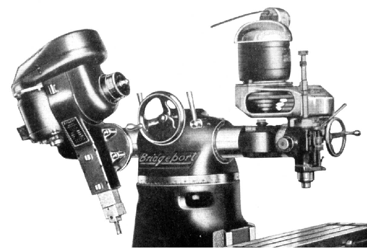
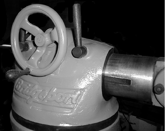
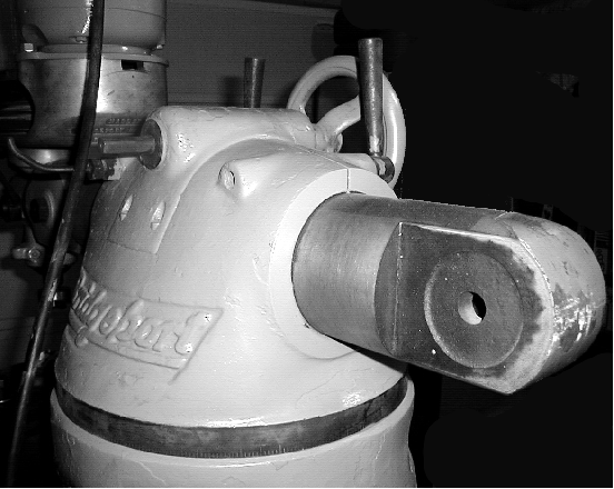
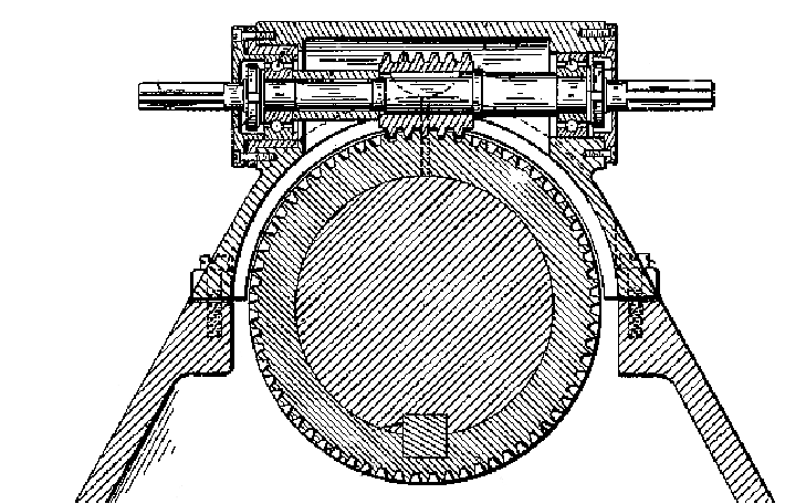
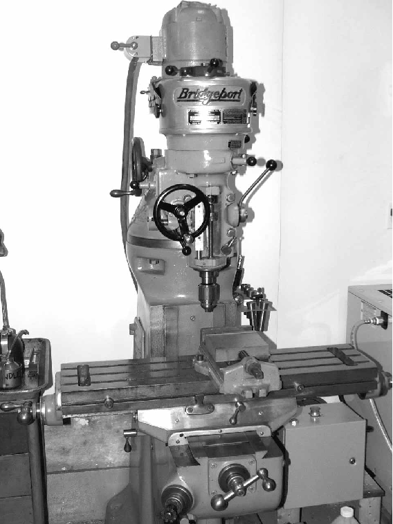
Rather less heavily built than the later versions, the original Bridgeport turret milling machine had a lower, more slender column with a storage cupboard in its left-hand side; it also had a distinctive 5-inch diameter round ram with most having a double swivelling yoke at one to take the vertical head end a simple clevis with a round-flange attachment at the other to mount the slotting attachment.  The clevis arrangement, which allowed the head to be both angled and "nodded", was fitted (on some examples at least) with "pin stops" to limit the travel to five positions at 30 degree intervals - this, in practice, enabled it to go 30 and 60 degrees off the vertical in both directions. Because the original Bridgeport was designed to carry the company's "Master Milling Attachment" the first type of "standard" Bridgeport head - which was of lighter construction than the later J Type - was known as the "M" Type.  At least two designs of column top were used to carry the round ram: the earliest had the top casting split vertically on the centre line with clamping bolts going from side to side - one side being  threaded the other bored as a clearance hole. The "bolts," were cross drilled and carried handles, about 8 inches long - their length being designed to safely limited the amount of torque it was possible to apply. A degree scale was engraved on both the ram and end of its housing. On the next version the ram was held within a substantial cap, split horizontally with two studs and nuts for clamping. As before part of the cap was cut away to carry a housing fitted with a cross shaft running on ball races (with a handwheel could be fitted at either end) that carried a "worm" gear that engaged with a large-diameter "wheel" (gear) surrounding the ram; the "wheel" carried a substantial key, attached by cap screws, that slid in a keyway running the length of the ram - the result of this finely-engineered assembly was that by rotating the handle (positioned half-way down the ram) the head could be made to angle over under precise control (sectional drawing at the bottom of this page). On some machines with the second type of housing (and they must be very rare), the ram could  also to be driven in and out under the control of rack-and-pinion gearing. The rack was cut into the ram and the pinion, formed with a hexagon end, set vertically at the left rear of the turret and arranged so that it could be lifted out of mesh to allow head rotation.. A small spring-loaded detent pin was provided to hold the pinion in the up position and was pushed in to re-mesh the gears.
The later turret housing (if not the first) was designed by Rudolf Bannow, one of the company's founders, and granted a United States patent ( 2,275,291) on March 3, 1942 after filing (rather late in the day) on April 4th, 1939.
If you own one of these interesting early Bridgeports, or have any advertising or technical literature, pictures of mint-condition examples or know more about them, the writer would be very pleased to hear from you.
   

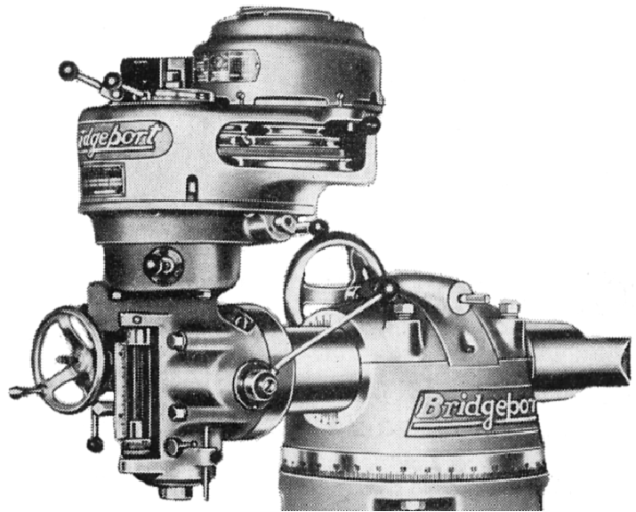
Original style of Bridgeport with vertically split top housing and a ram with a clevis fitting at both ends--in this case carrying a slotting head at one end and the "M" Head at the other - as illustrated in a rare export catalogue

Above and below: the first batch of Bridgeport millers had their top casting split vertically with locking bolts going from side to side; one side was threaded the other bored as a clearance hole. The "bolts," were cross drilled and carried handles, about 8 inches long - their length being designed to safely limited the amount of torque it was possible to apply. 

Using the double clevis arrangement of the end of the ram the head could be moved into a bewildering number of positions--one of the attractive features that made the Bridgeport such a successful machine

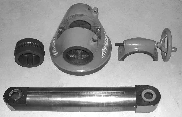
The next stage: component parts of the (horizontally-split) Mk. 2 top casting:
top left - the circular wheel that surrounded and rotated the ram and so inclined the head;
top middle - horizontally split circular top cap with its two vertical clamping bolts; top right - inserted section carrying a cross shaft and worn; bottom - ram with a clevis at both ends.

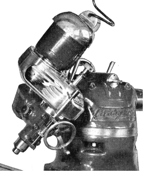
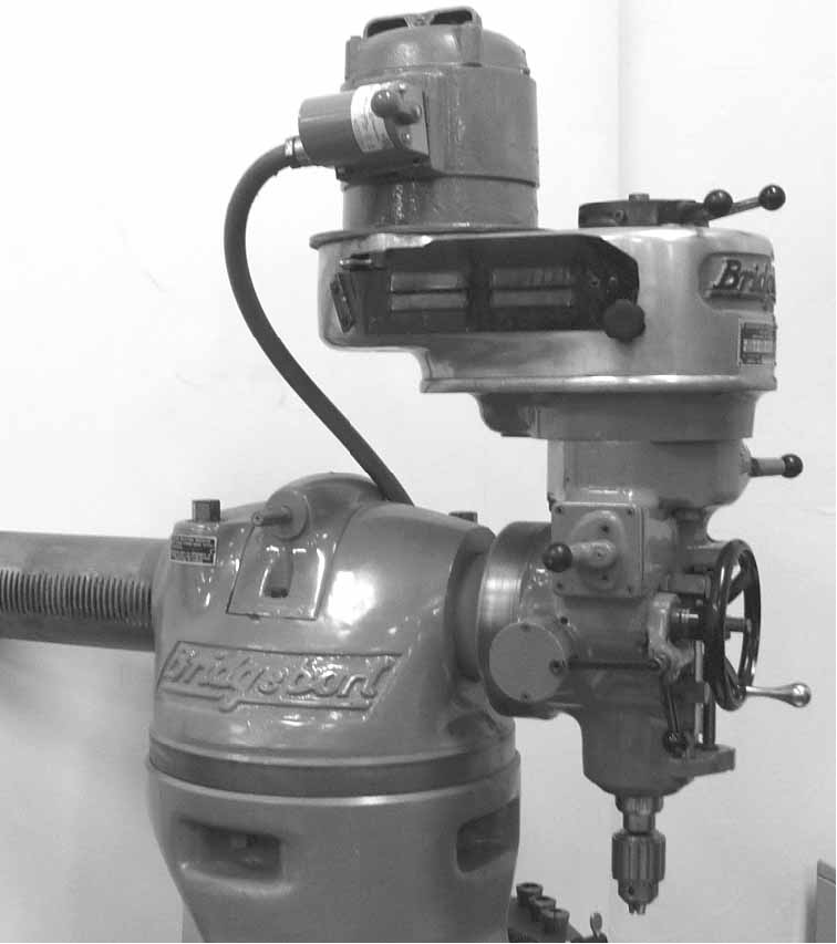
Above and below a post-WW2 example of the original Bridgeport carrying, in this instance, not an original "M" Type head but one the later and more-heavily constructed "J" Type with the low-height "pancake motor". The ram fitted to this particular machine had a clevis fitting at the rear only with the vertical head bolted solidly (and hence more rigidly) to a flat face.

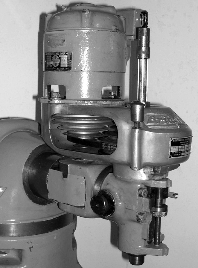
Post-WW2 M Type head

The "pancake" motor saved a good deal of headroom compared with the earlier fitting illustrated below

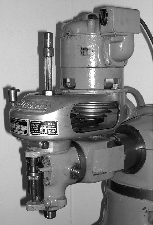
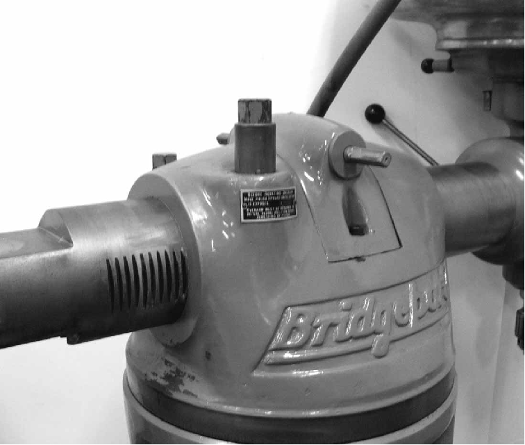
The top of the pinion, formed as a hexagon, can be seen just to the left of the large (rotational) handwheel
One some round-ram machines with the second type of top-column housing  (and they must be very rare), the ram could  not only be rotated by the usual worm-and-wheel arrangement but also to be driven in and out by rack-and-pinion gearing. The rack was cut into the ram and the pinion, formed with a hexagon end, set vertically at the left rear of the turret and arranged so that it could be lifted out of mesh to allow rotation. A small spring-loaded detent pin was provided to hold the pinion in the up-position and was pushed in to re-mesh the gears. The design was simple and only allowed horizontal feed when the head was positioned vertically.
With thanks to Dave Dunbrack in the United States for the photographs.

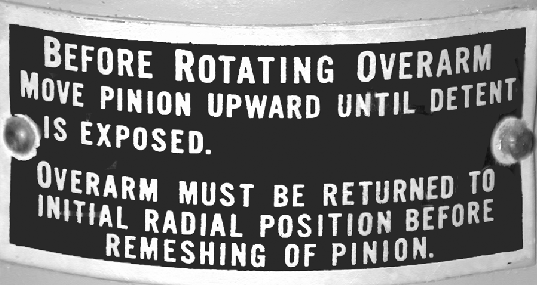
A small plate gave instruction concerning disengagement to allow head rotation

Ram fully in

Ram fully extended

As on the standard machine only a single handwheel to rotate the ram was provided. However, it could be fitted at either side of the cross shaft.

A complete and original early version of the round-ram Bridgeport-ram Bridgeport

High-quality Handbooks, Parts Lists and Spares are available
for most Bridgeport machines

Bridgeport Home Page

Bridgeport Vertical Heads & Attachments

Original Bridgeport Round-ram Model

Bridgeport Accessories   

The Bridgeport Miller at Work

Vertical Attachments by Halco and Kerney & Trecker (Dalrae)

Bridgeport Table Power-feed Units   

Bridgeport Serial Numbers

Bridgeport Horizontal Stub Miller

Further Bridgeport Company History and "Building a Bridgeport"

Bridgeport Series 1 CNC Miller (based on the standard machine)

Bridgeport Larger CNC Millers (Interact, APC, BPC)

Late Edition, Series 1 Ram-head Miller Catalogue


Computer-modelled Illustration

Bridgeport Millers
Original "Round-ram" Model
email: tony@lathes.co.uk
Home   Machine Tool Archive   Machine-tools Sale & Wanted
Machine Tool Manuals   Catalogues   Belts   Books   Accessories