|
|
|
email: tony@lathes.co.uk
Home Machine Tool Archive Machine-tools Sale & Wanted
Machine Tool Manuals Catalogues Belts Books Accessories
Unknown Lathe No. 41
Miniature Precision Backgeared
and Screwcutting Lathe
Continued on page 2
Do you recognise it ? If so, please do email the writer
Unknown Lathes Home Page
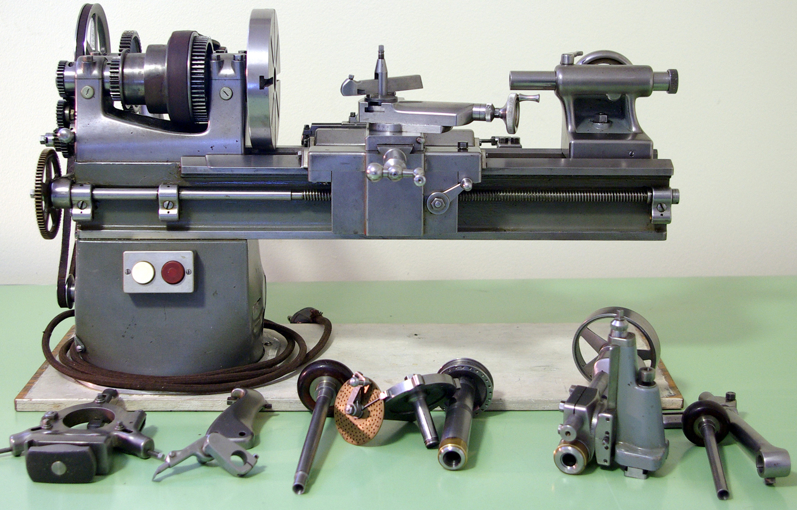
Beautifully executed - with the most delicate of detailing and a wonderfully fine cosmetic finish to both castings and machined parts - this 2-inch centre height by 7-inches between centres backgeared and screwcutting machine must represent the apotheosis of miniature lathe design. Is apotheosis too strong a word? From the Latin meaning to make divine, it refers to humans whose abilities caused their (allegedly) elevation to the Pantheon. However, even a cursory examination of this lathe must lead the reader to conclude, if a Pantheon for lathes existed, this would be one eminently qualified for admission.
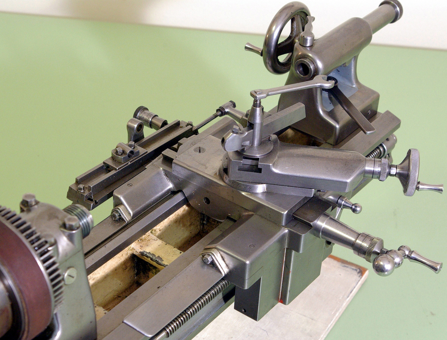
Where and by whom the lathe was made is a mystery, but it may be (like the Rolls Royce) that it was built to meet a very specific specification for use in an experimental or scientific department. However, it's just as likely to be the work of a retired, high-skilled machinist who, instead of building the usual steam model, turned his attention to a machine tool. As the V-belt motor drive appears to be original, this (and other design clues) might date the lathe between the mid-1930s and late 1950s - the first use of V-belts on small lathes dating from 1931/2. Of American manufacture (the motor, electric cord and switches appear correct for the period) the design reflects some features of toolroom practice as found on larger lathes with points including: a bed with a front V-way having a wide and shallow outer face backed by a steep and short inner (just like a Wade 8A); bedways running on past the front and back of the headstock that allowed the saddle, with long, equally proportioned saddle wings (with a cover to guard the front bedway) to run the tool right up to the spindle nose: a centrally positioned cross slide; an especially deep apron; a particularly stiff, large-bore spindle with a 3/4" x 16 t.p.i. nose; a front spindle bearing clamped down by four bolts; a thick, T-slotted faceplate; a worm-driven, fine-feed tailstock barrel that appears to have a quick-disengagement mechanism allowing the spindle to be positioned by hand - and even six closely-spaced gib-strip adjuster screws on the cross and top slides to allow the setting of a smooth and even sliding action. The range of accessories is also impressive: fixed and travelling steadies, a headstock-mounted dividing attachment and a vertical milling slide with a "geared-up" collet-holding high-speed milling and grinding attachment. The cost of manufacturing this lathe (with both its fit and finish compare most favourably with that on the Rolls Royce) must have been astronomic in both time and money. With no external oilers to be seen - but screw-in cover caps on the front face of the bearing housings - it is almost certain that the spindle is lubricated from sumps with the oil lifted (less any dirt) by wicks. Headstock spindle collet size is 0.312" (7.94 mm) with threads of 40 t.p.i x 0.268" - dimensions that match those of American Marshall/Peerless watchmakers' lathes.
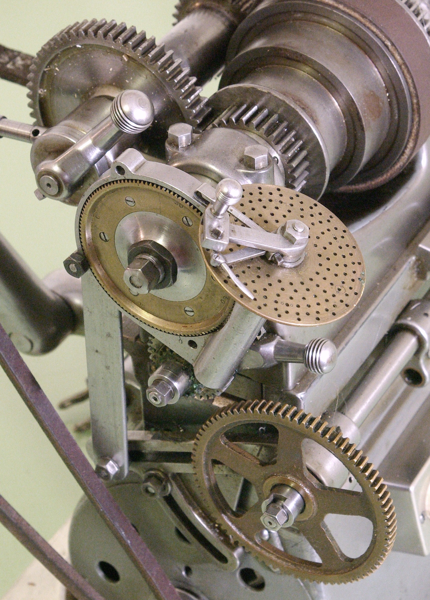
Grasped by proper half-nuts, the 16 t.p.i. leadscrew is driven through a tumble-reverse mechanism, always a difficult thing to engineer on a very small lathe. In this case, the solution is to allow the changewheel bracket to pivot so that its lower end falls a little below the bottom edge of the bed. One oddity is the lack of a hand-driven carriage feed; it might have been arranged by a removable handle on the end of the leadscrew - though the lack of an extension and tight engineering at the point would seem to preclude it. While there two tapped holes provided on the left-hand face of the apron that could have been used to mount a carriage-handle bearing block (with a gear running on the lead screw), that would be at variance with a machine of this quality. The holes also appear to be equally spaced about the line of another missing part, an auto-disengagement or threading stop rod that might have been carried in the two brackets below the leadscrew. However, both the stud gear (the first gear in the changewheel train) and the screw gear (the gear on the end of the leadscrew) are both machined with slots; could these have been used to mount a removable handwheel that would have given two rates of feed, one direct, the other geared down?
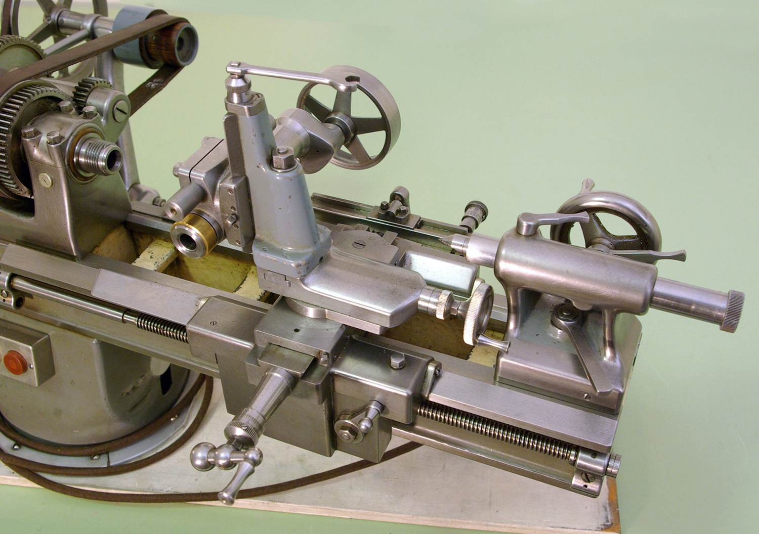
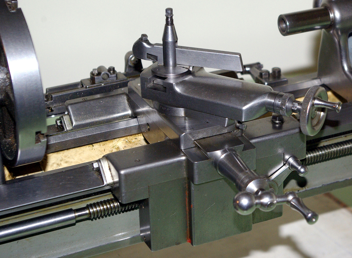
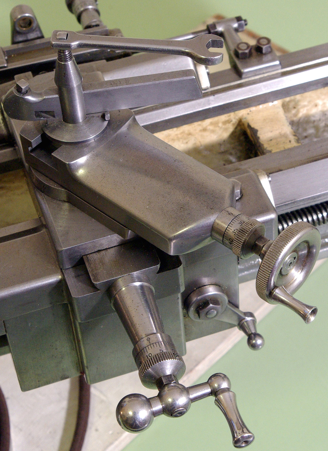
Of the most elegant proportions, the compound slide-rest assembly is of a conventional arrangement, with both slides having six gib strip adjustment screws. The top slide, able to be rotated through 360°, is obviously fitted with an inverted cone on its base that, once inserted into the cross slide, is locked down by the square-headed screw seen to the right-hand side of the cross slide's front face. One more unusual feature - and again possibly unique - is the use of a "lantern" toolpost where the toolholder sits on a rocker wedge with a concave instead of convex base - the design perhaps being superior in getting the cutting forces to bear down on what amounts to a "wedge-shaped" surface rather than trying to push the rocker back inside a concave groove?
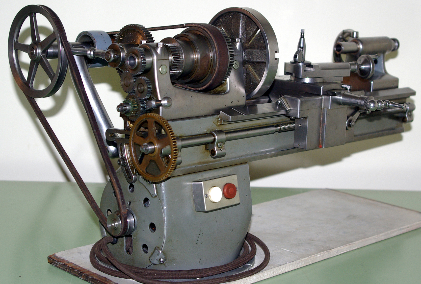
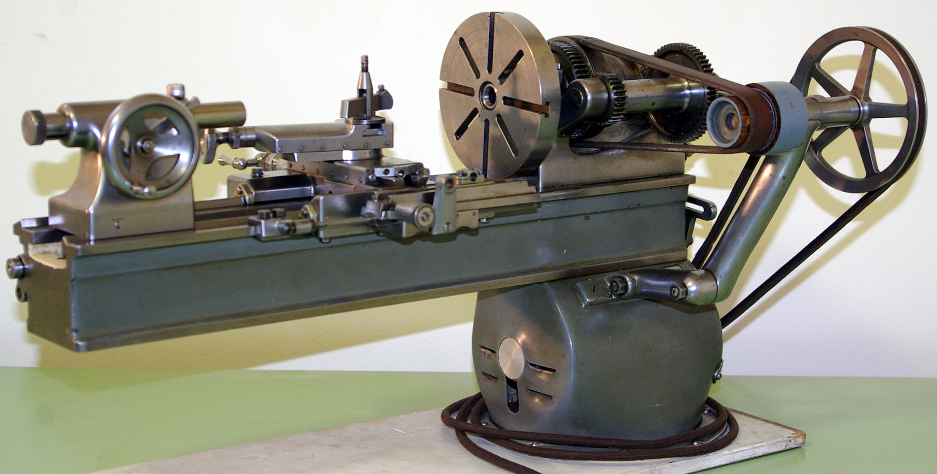
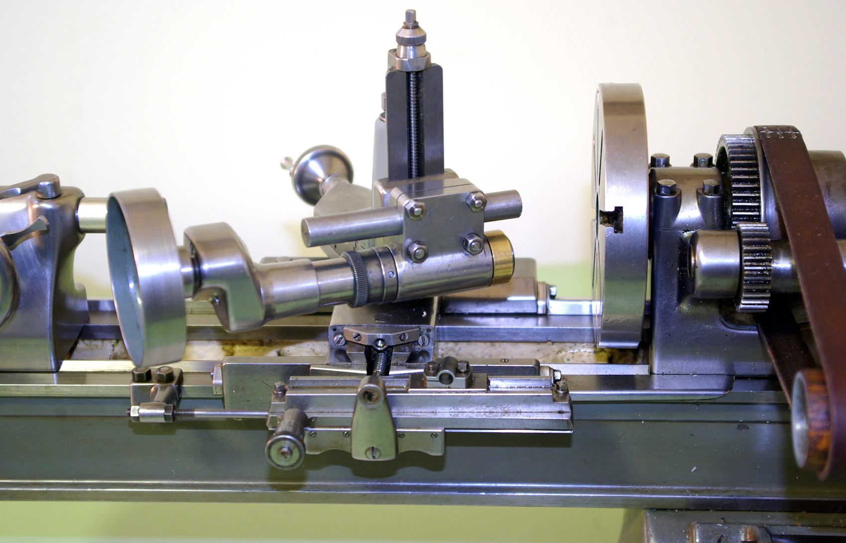
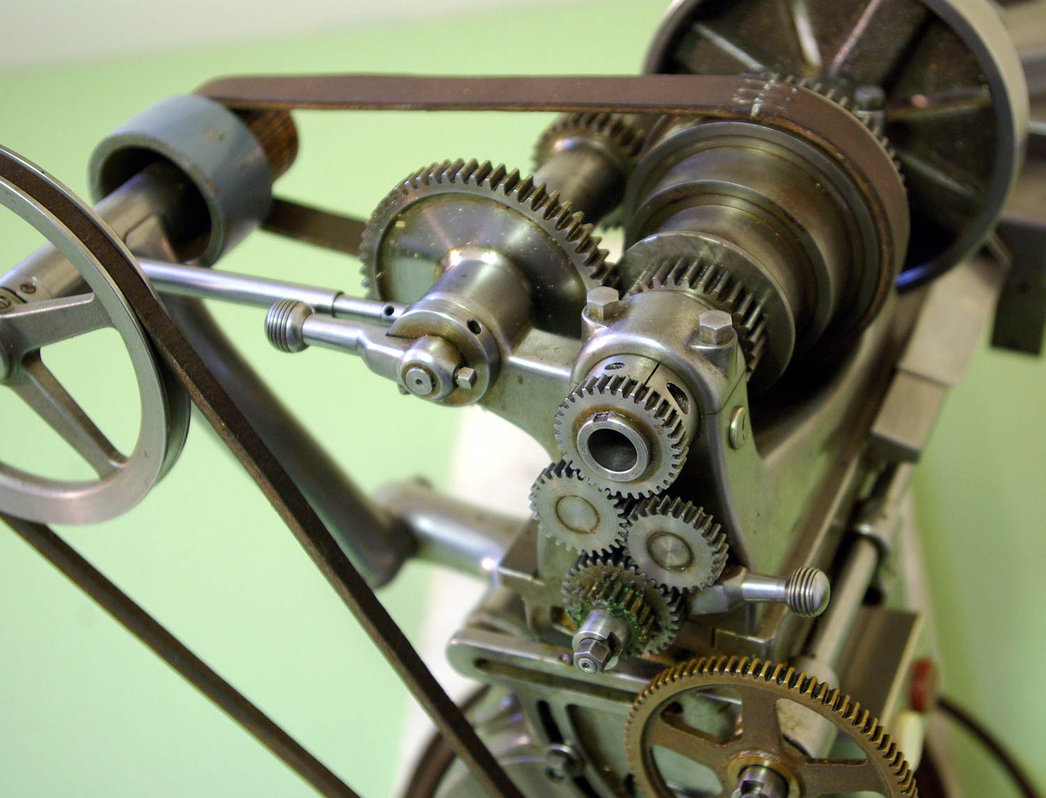
The drive system - with the bed bolted directly to the motor and the countershaft cantilevered from the back - is, if not unique, is very unusual (could this have been adapted from industrial sewing-machine practice?). The single tapered arm carrying the 3-step flat-belt pulley is bolted to a bracket fixed to the back of the motor, the design allowing the unit to be moved to tension the belt as required. Running in a single bearing at the top of the arm, the countershaft spindle carries overhung pulleys, drive on one side and driven on the other. This arrangement - a motor bolted to the bed - brings in its wake the chance that vibrations from the 1-phase motor (not always the smoothest-running of devices) might pass to the workpiece.
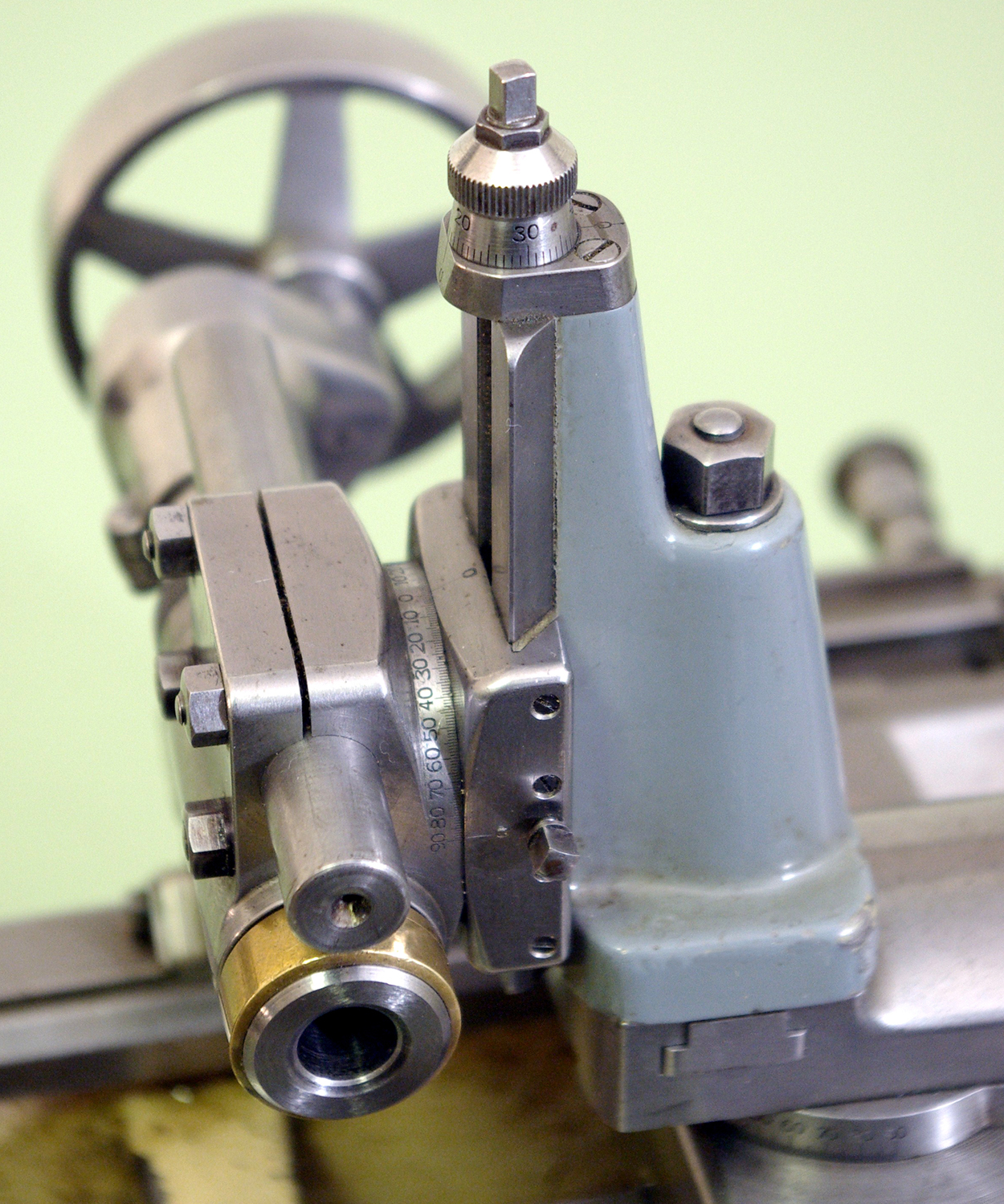
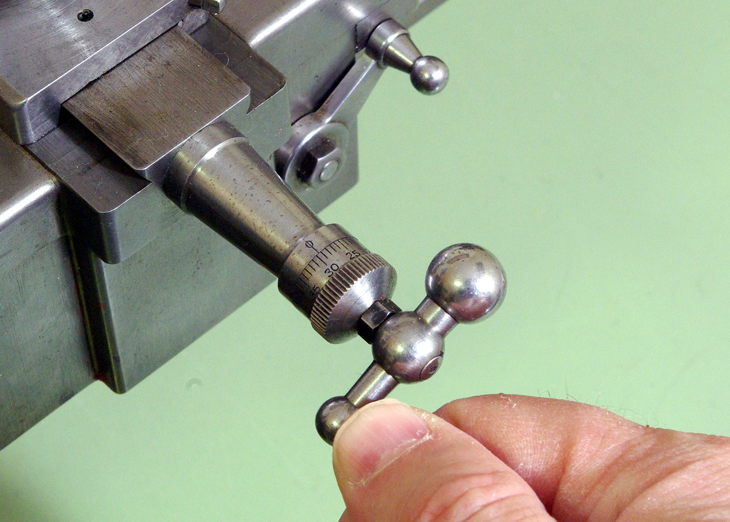
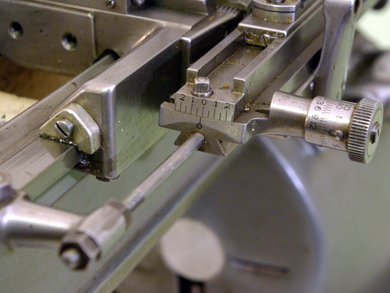
Beautiful details abound: the fitting of a taper-turning unit whose setting is altered by a screw fitted with a vernier equipped dial; the tapered extension housing for the cross-feed screw; the concave handles on cross slide, top slide and tailstock handwheel; finely-fitted way covers bolted to the front face of the apron arms; the zero mark for the cross-slide micrometer dial set slightly to the left of vertical to align more easily with the turner's natural eye line - and even the wrenches for the tailstock and toolpost being specially made and of elegant proportions. Pictures continued here
|
|
|
|