|
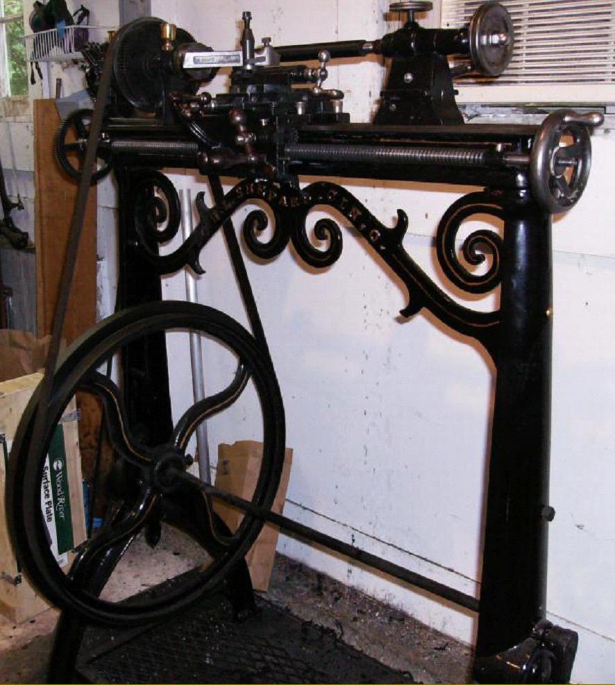
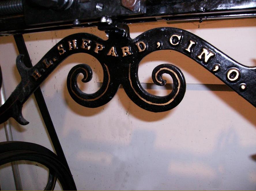
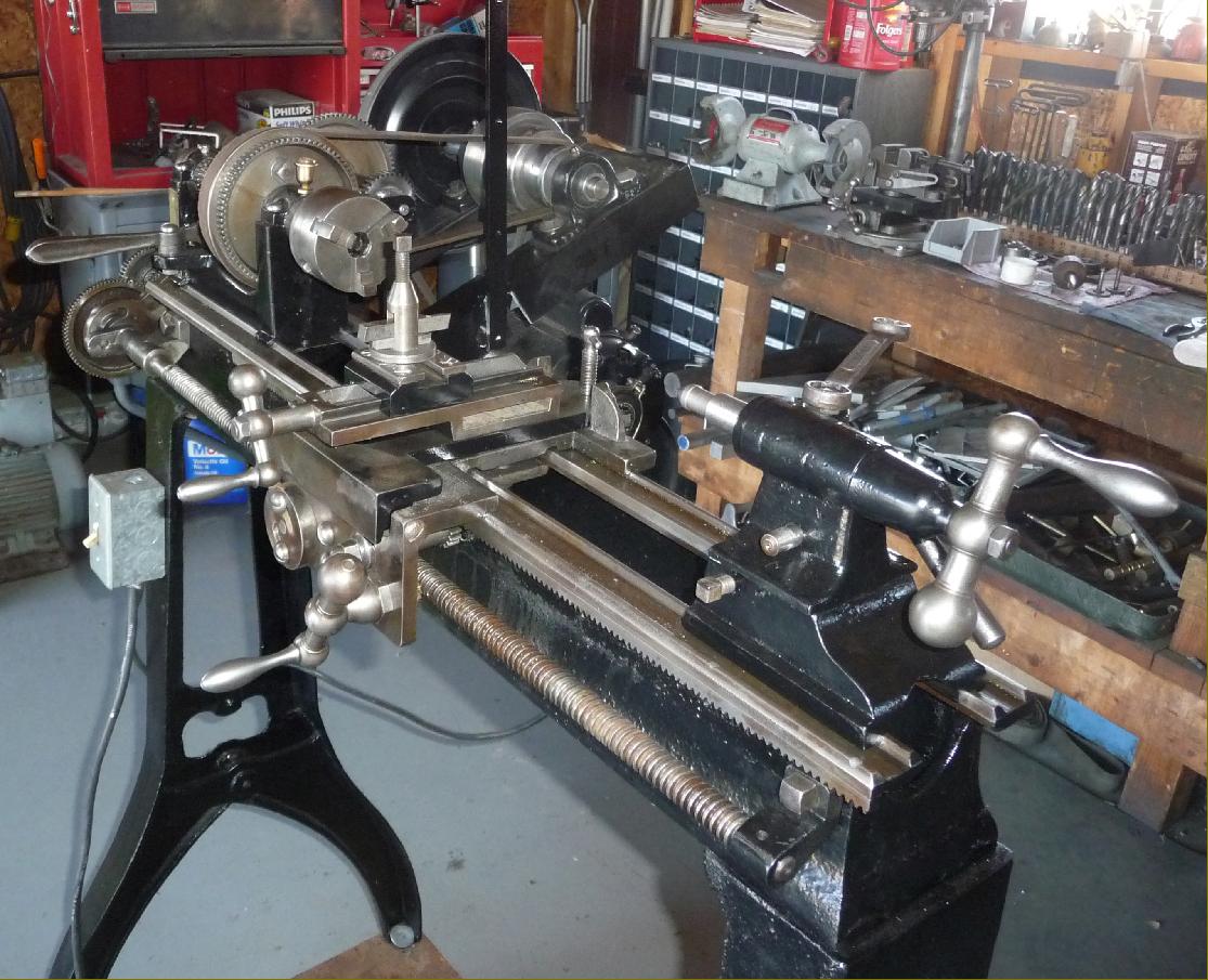
H.L. Shepard "Sterling" lathe
Manufactured in the United States by H. L. Shepard & Co. of Cincinnati, Ohio, and introduced by them in 1919, the "Sterling" lathe was typical of the simple, economically priced general-purpose "jobbing" lathes offered in trade catalogues such as that issued by the well known English suppliers Burton, Griffiths & Co. Ltd. The market for such machines, from around 1890 until the 1940s, was automotive garages, bicycle, small repair shops and training establishments from around 1890 until the 1940s.
Overtly evocative names such as "Sterling" were used by a retailer (the names were often in parenthesis) to hint at an imported machine of hidden origin (often from continental Europe and the United States) - but in this case, might H.L.Shepard & Co. have received a significant order from London-based Burton, Griffiths & Co. and have named the lathe appropriately?
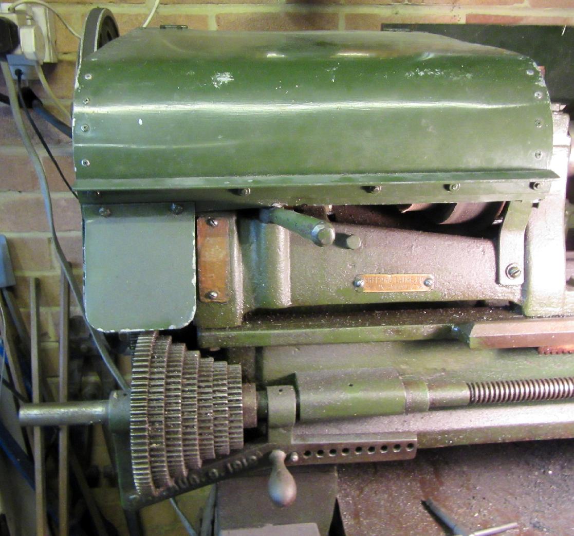
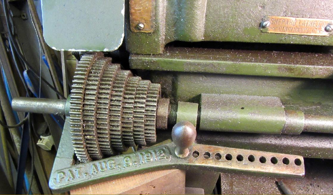
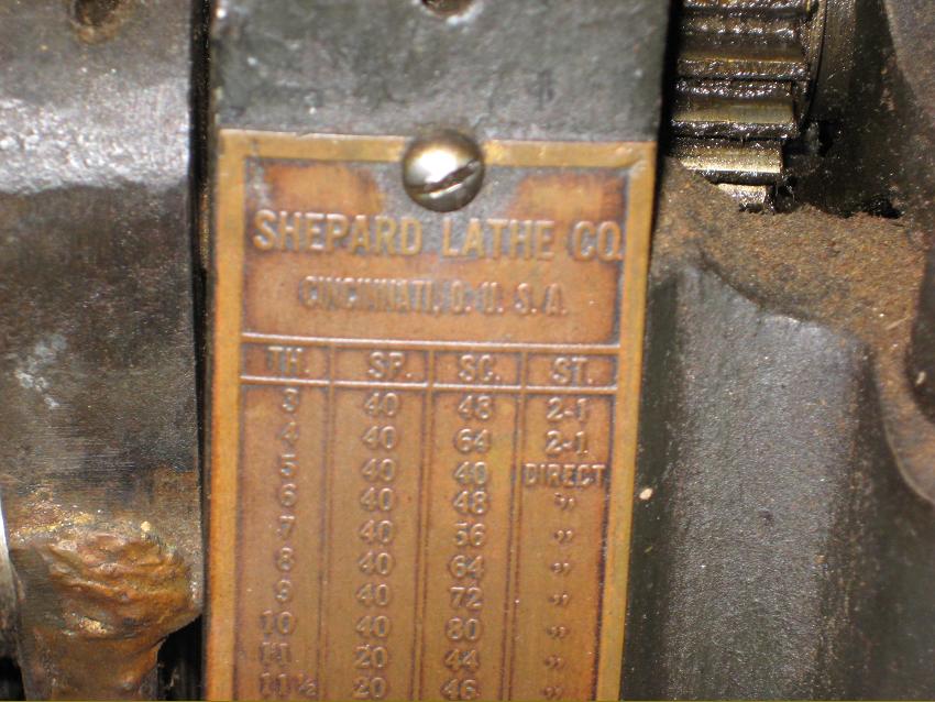
The firm of H. L. Shepard & Co. was founded in 1875 - and then reorganized in 1898 as the Shepard Lathe Co. with production of their lighter lathes using the brand name Shepard continuing, it is believed, until the mid-1920s. As a point of interest, another Company with a similar name (and not connected with H. L. Shepard & Co.) was Shepard, Lathe & Co. a firm founded in 1845, as S. C. Coombs & Co. Being a joint venture by Samuel C. Coombs, Russell R. Shepard and Martin Lathe - yes, he really was called Mr Lathe… In 1853, when Mr. Coombs left, the Company was reorganised as Shepard, Lathe & Co. and then, in 1864, when Shepard retired, as Lathe & Morse.
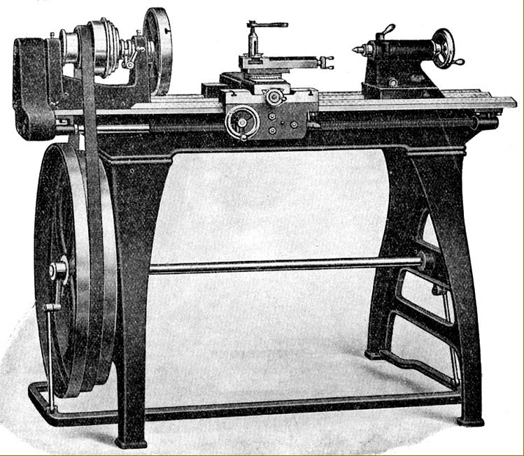
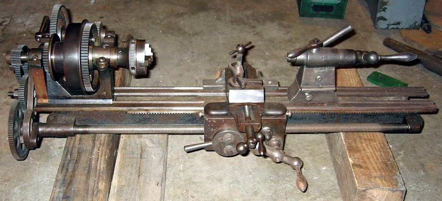
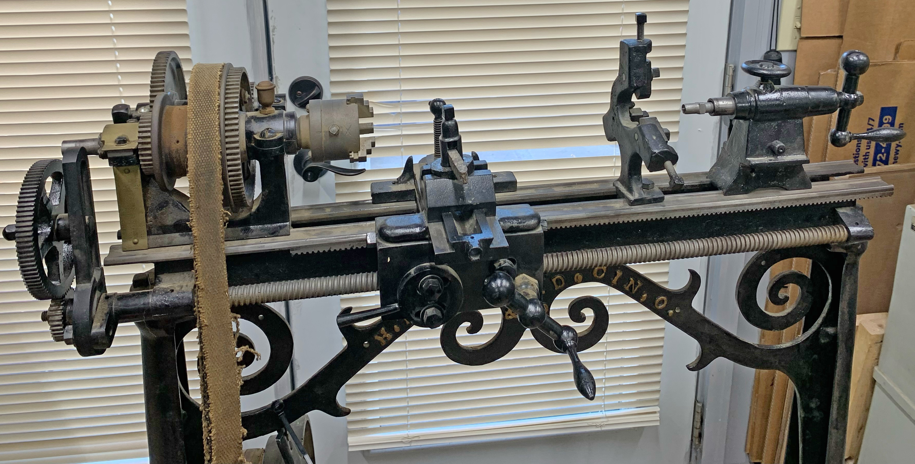
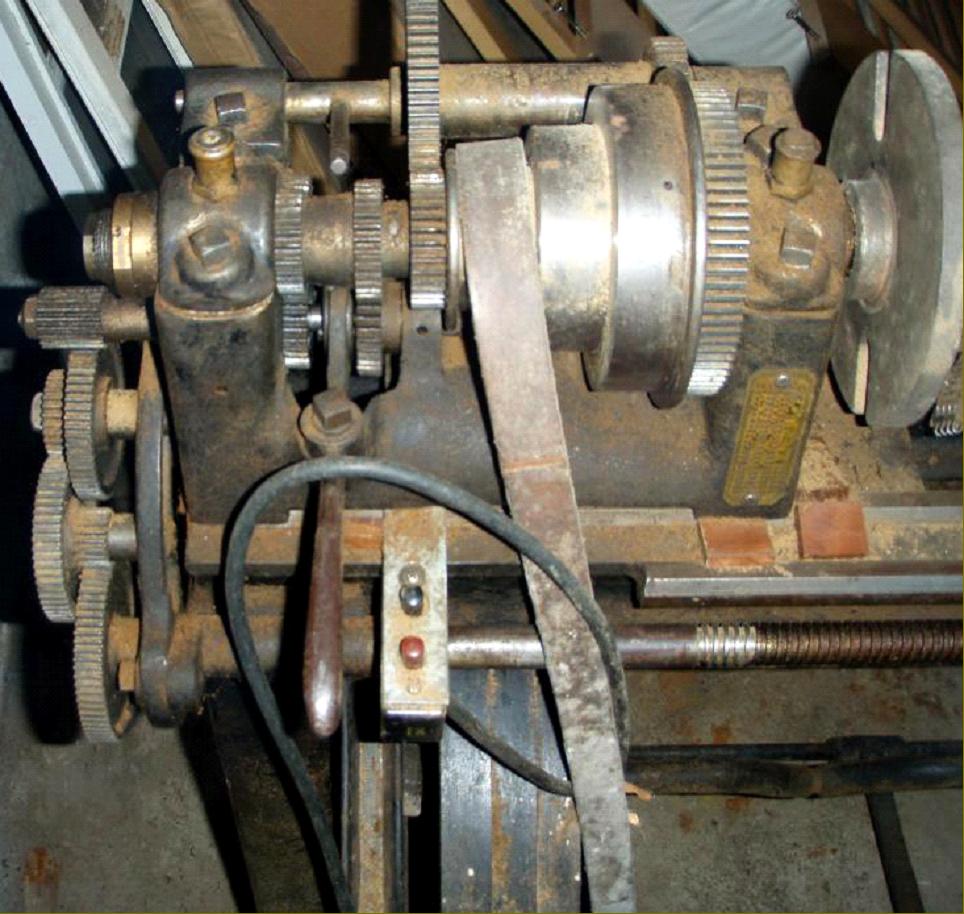
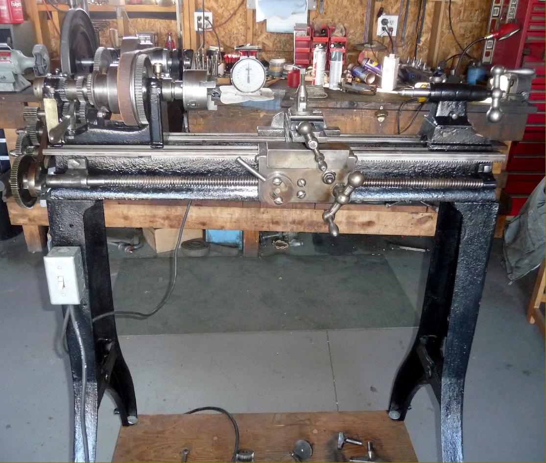
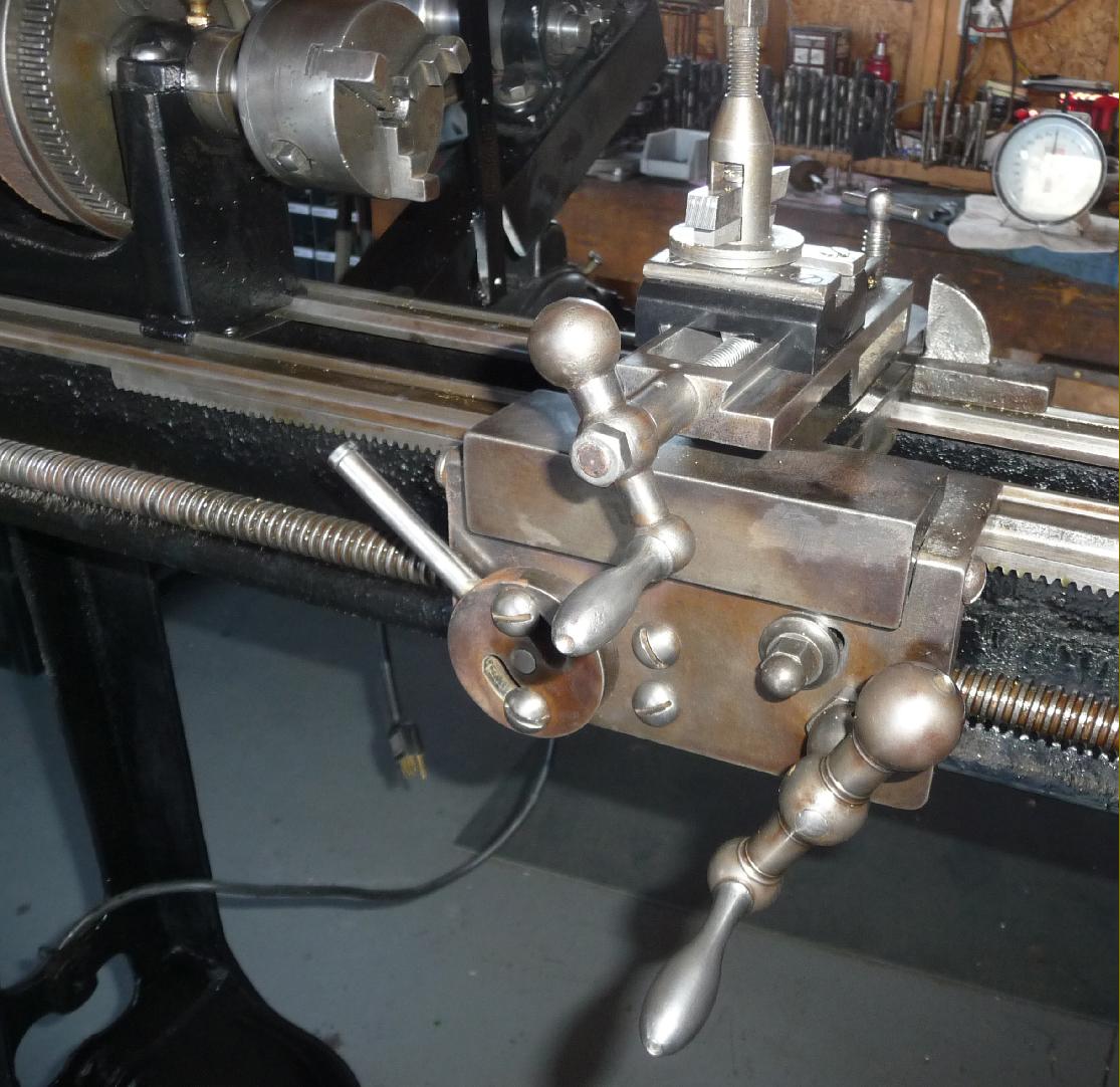
Built along similar lines to the better-known Seneca Falls and South Bend lathes, although treadle powered and of a simple layout, the 6.5" x 24" or 36" 'Sterling' was a soundly constructed backgeared machine with screwcutting by changewheels - a gearbox was not offered - that could generated pitches from 3 to 40 t.p.i. There was no tumble reverse to isolate the drive from the leadscrew and provide an immediate switch from right to left-handed threads - indeed, the generation of the latter appears to have been impossible, there being no mention in the literature, nor evidence in the illustration, that a stud was provided to mount the extra changewheel required. A thread dial indicator was "arranged in conjunction with the apron handwheel, greatly simplifying the chasing of threads"; this meant that either the makers were hopelessly ill-informed about the realities of the rack-driven carriage and 15/16" x 5 t.p.i leadscrew remaining in synchronisation or, rather more likely (as on the Myford ML10 for example) the carriage was driven along the bed by a gear working against the leadscrew - a solution often used on light lathes, but one that must be questioned when employed on one of this weight and capacity. The leadscrew was slotted along its length to drive (at extra cost) a power cross-feed mechanism.
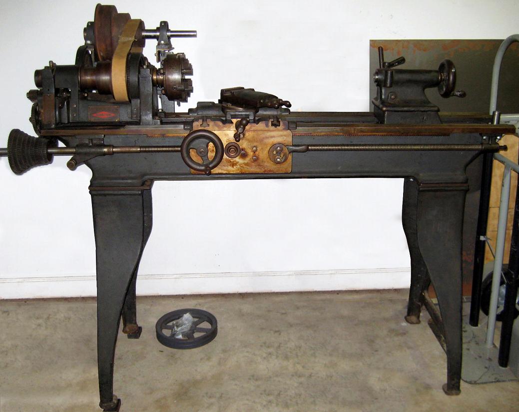
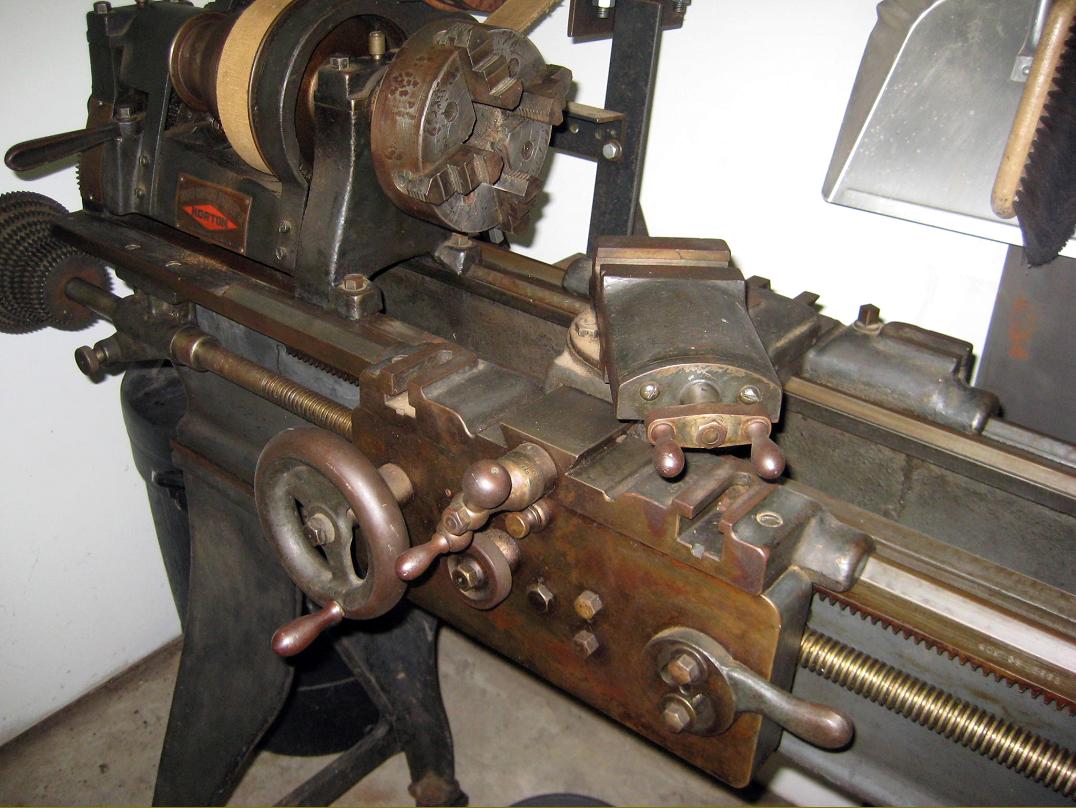
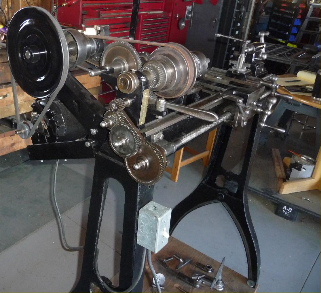
Of straightforward design, the headstock held a high-carbon steel spindle (with a 1.5" x 10 t.p.i nose a slender 11/16" bore) that ran in white bronze bearings of "large lead capacity". The bearings were carried on un-braced "posts" when many similar lathes had theirs stiffened by a raised front to the casting that rose to the centre of the bearing line. Strangely, despite the parsimony evident in other aspects of the lathe's construction, the headstock cone pulley held a set of epicyclic reduction gears within its largest diameter. The gears, which provided a reduction ratio of 4 to 1 against the more normal 6 to 1 of a conventional backgear, were engaged by a simple, exposed toggle lever and could be put into and out of mesh while the lathe was running. As a useful bonus (though the form of mechanism is not known) the spindle could also be stopped by moving the lever to a third position, a handy feature that allowed the very heavy flywheel to keep turning whilst adjustments were made to the job (the considerable amount of time wasted stopping a heavy flywheel and then bringing it back up to a working speed is one of the most serious disadvantages to any foot-powered lathe).
Because the carriage was arranged to run past the front of the headstock the 11-inch long saddle was able to be fitted with four equally-disposed T-slotted wings, so converting it into a perfunctory boring table. The cross slide was positioned exactly in the middle of the saddle, where it was well supported and the tool forces spread more evenly along the bed. As standard only a plain (cross) slide was provided, but a compound slide rest was available as an option.
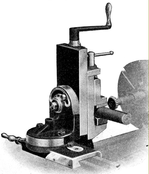
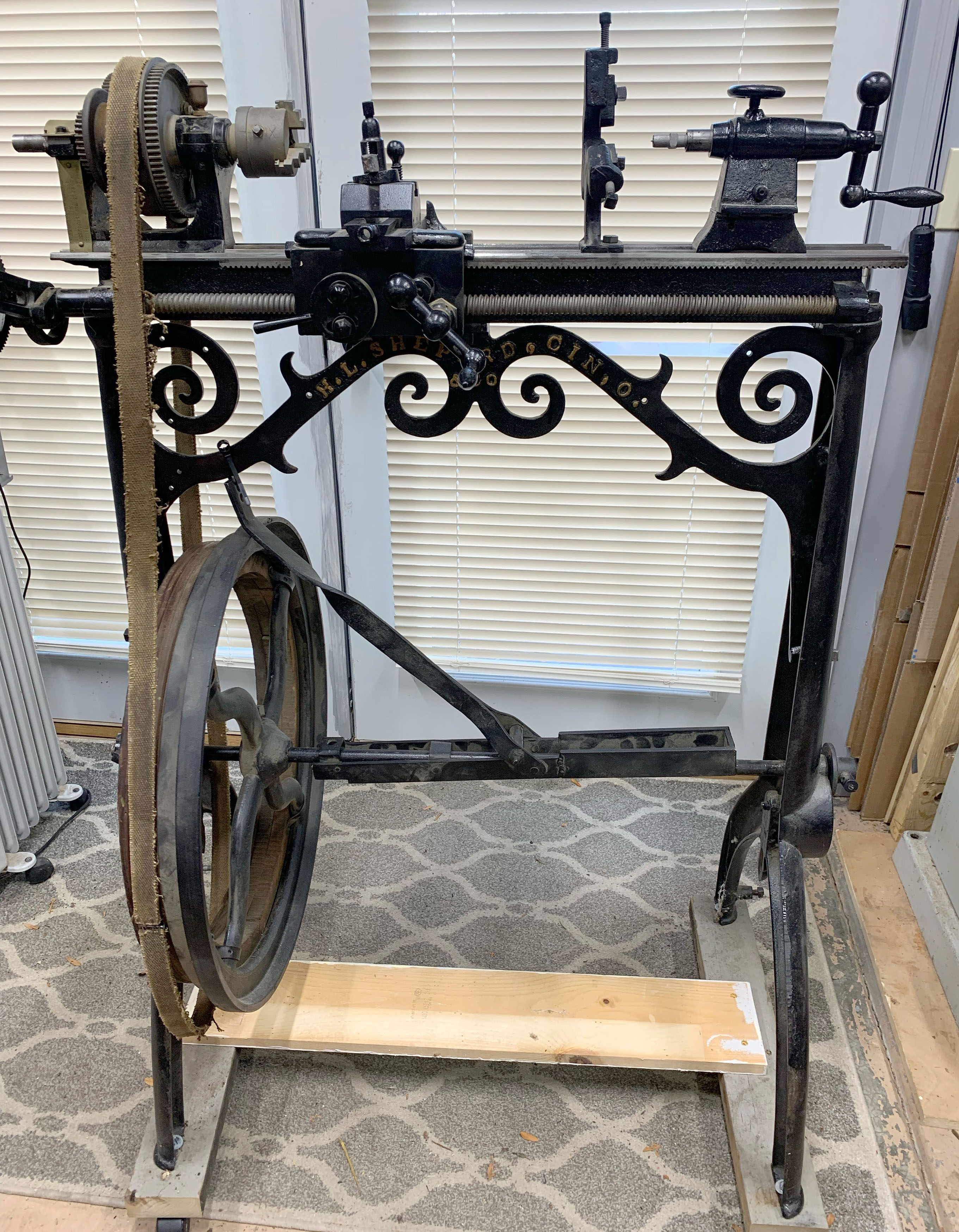
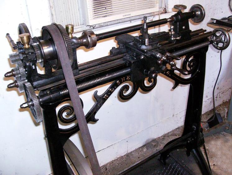
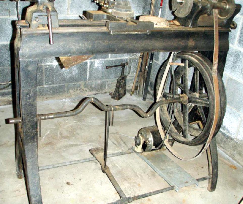
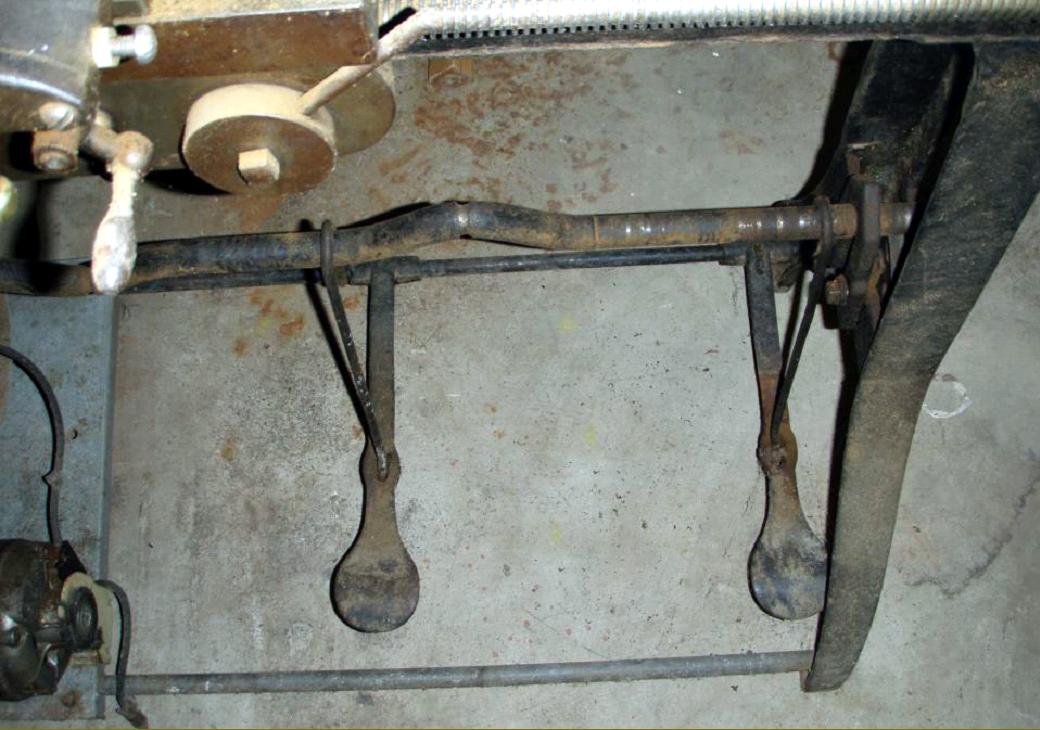
Made, as would have been expected, in cast iron, the stand carried outboard of the left-hand leg a very large flywheel supported on a long pin that ran through both legs and which picked up power from each end of the full-length foot pedal. The length of the pedal was such that both left and right-footed operation would have been possible - or two long-suffering apprentices cajoled to stand side by side and provide sufficient power to cope with heavier jobs.
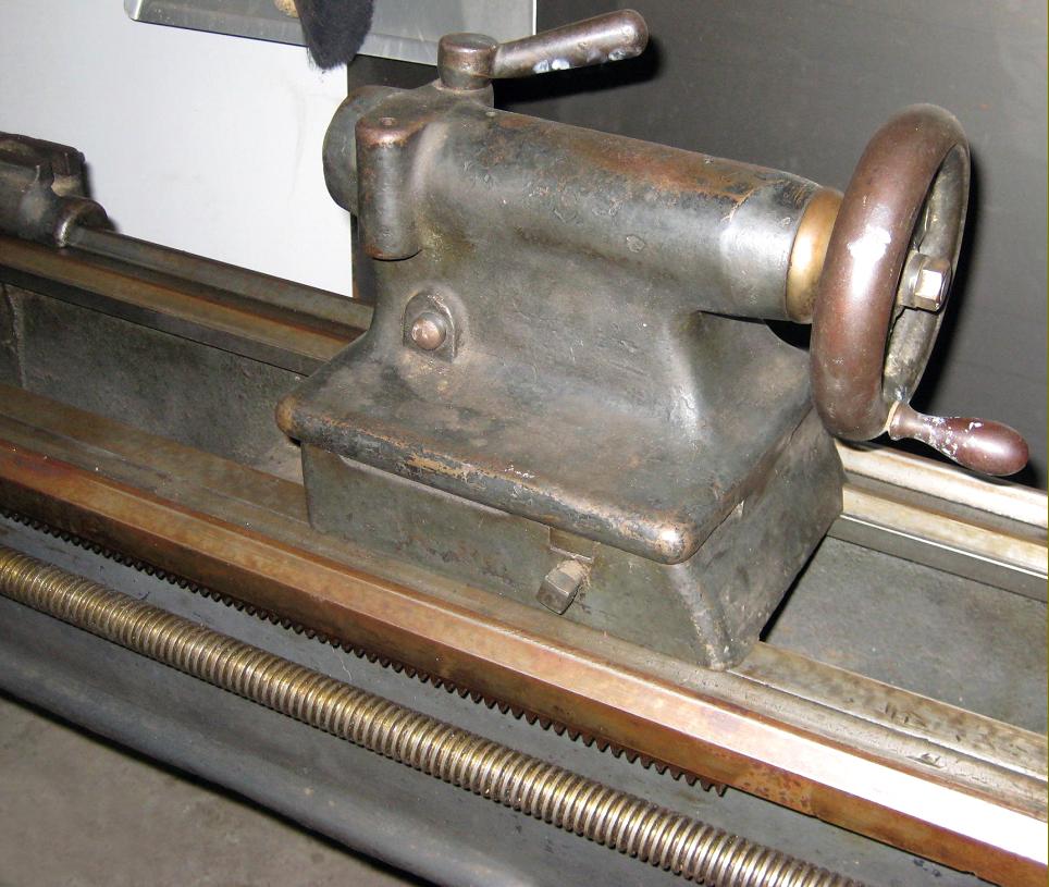
Heavily built, the set-over tailstock carried 1.25-inch diameter barrel with a No. 2 Morse taper and 1/16" ruler graduations.
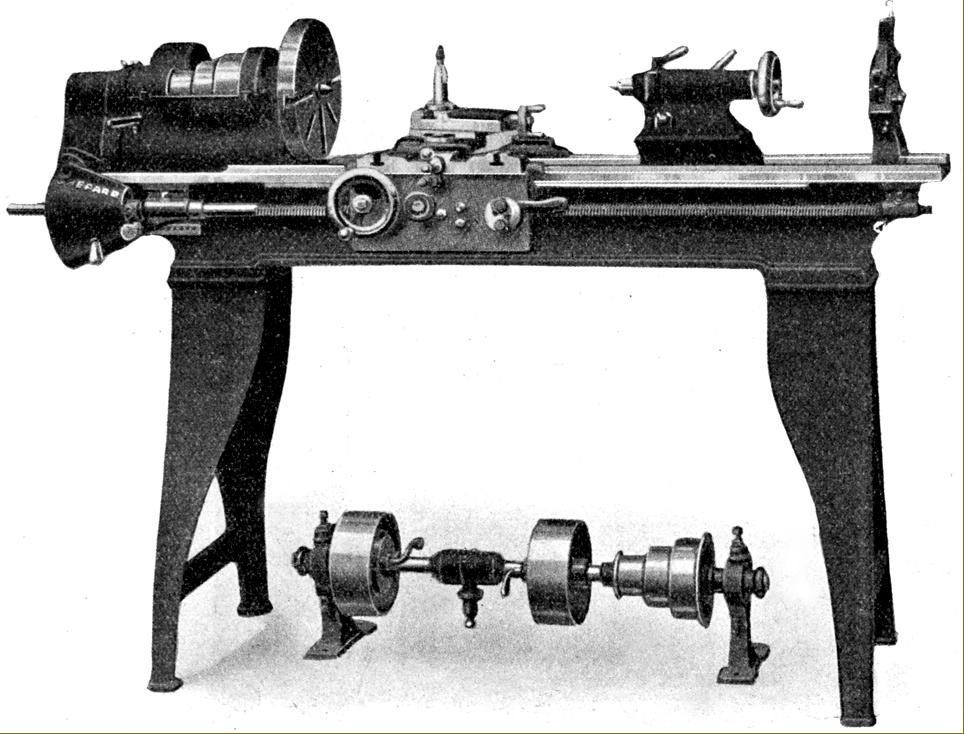
Supplied as standard with the lathe was: a useful T-slotted faceplate, fixed steady, guards for the changewheels, a set of spanners and either the treadle stand illustrated or a wall-and-ceiling countershaft unit to accept motor drive. Amongst the options available were metric changewheels, a six-station capstan turret, draw-in collet set, power cross feed and a vertical milling slide. In basic trim the lathe weighed 500 lbs.
By 1921 H. L. Shepard & Co had moved from Cincinnati to Rising Sun, in Indiana, and made some changes to their product line, though few details are available. What is known is that their top-of-the-range lathe was a gap bed "New Shepard" and the evolving Sterling was available as not only as a treadle machine, but also "belted" - presumably meaning driven by a countershaft - or by single motor drive, possibly a reference to a built-on self-contained system. A major change was the dropping of the planetary reduction gears and substitution by what the makers described as, "A completely enclosed gear head with a single-pulley drive."..
|
|