|
Home Machine Tool Archive Machine-tools Sale & Wanted by Kneller Engineering |
||
|
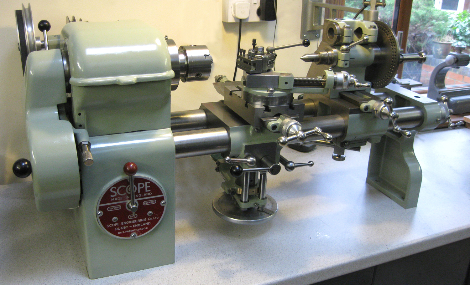
Manufactured by Kneller Instrument & Tools Ltd of Caldecott Street in Rugby (although it appears to have been marketed by a separate Company, from the same address, Scope Engineering Ltd.) the 4.25-inch centre height by 14.5-inch between centres, backgeared and screwcutting "Scope" was in production by 1947. In 1958 Kneller moved to a new factory, in Daventry, and was eventually to make, from 1964 onwards, a lathe bearing their own name, the Kneller Combination Machine. Kneller, founded in the late 1930s by Mr Kneller, was to become a well-established and very successful firm of precision engineers who did much sub-contract work for the aircraft industry including parts for the Concorde prototypes and many jobs for Rolls Royce. |
|
|
||
|
Continued: |
|
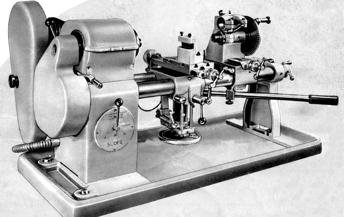
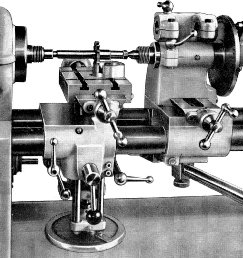
The Scope set up as an ordinary centre lathe--but with the cutting tool held in a slot on a special plain column that replaced the standard unit. By this means discs up to 8-inches in diameter could be turned over the saddle. |
|
|
|
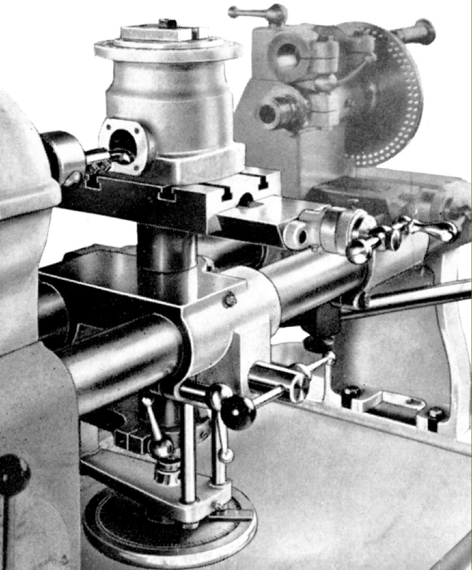
Instead of using a compact bevel-gear drive of the type used to lift the knee of many milling machines the designer of the Scope opted for a rather crude and awkward-to use direct screw feed to elevate the boring table through a range of 3 inches. |
||
|
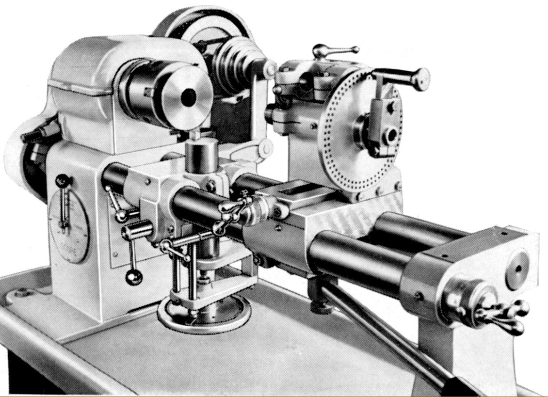
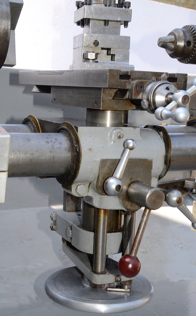
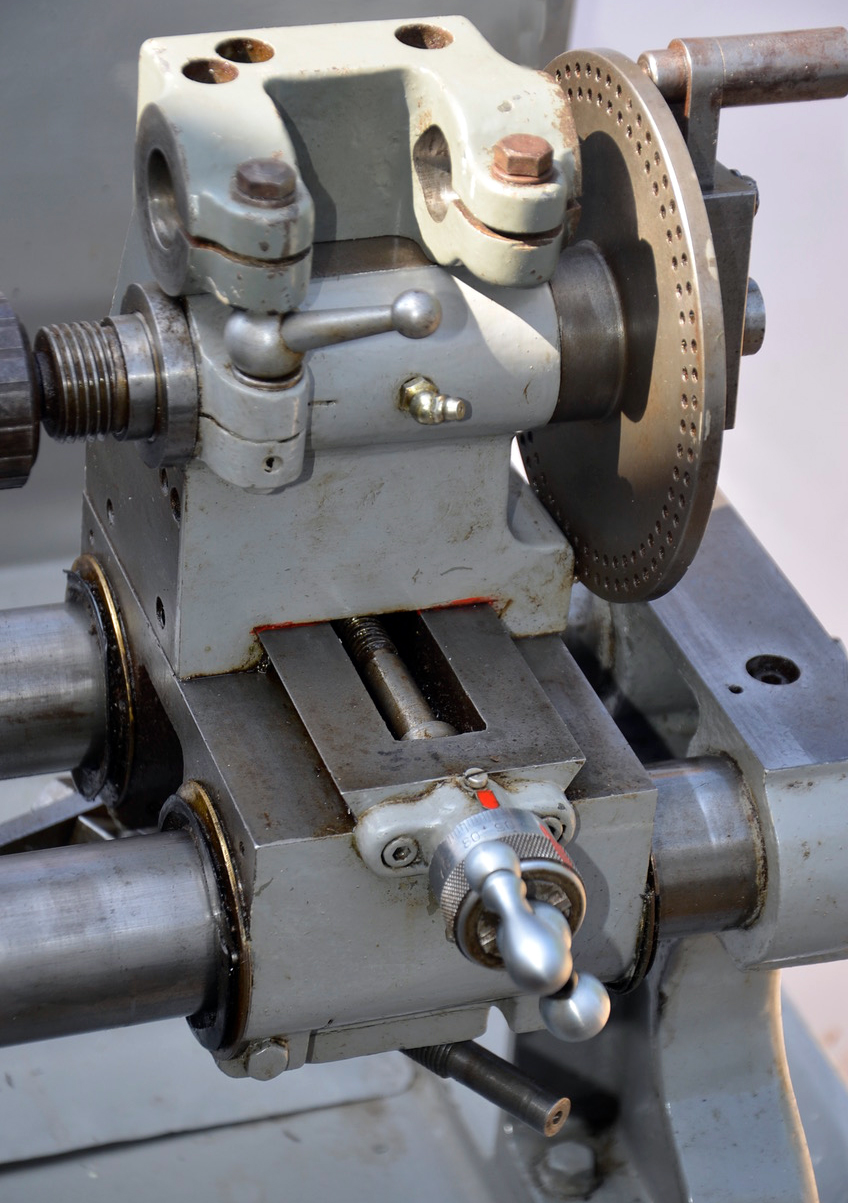
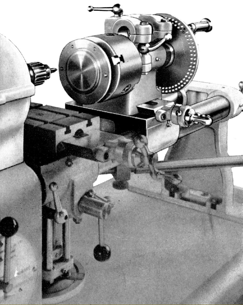
Designed to convert the lathe into a shaping machine the tailstock was very highly unusual in that not only did it have an upper section sitting on a slideway that allowed it to be moved across the bed (a system offered as an option on some American precision plain turning lathes), but also carried a barrel threaded to accept a chuck and fitted with a 6-inch diameter division plate with rings of 60 and 24 (or 60 and 56) holes. The tailstock was arranged to be moved along the bed by the action of a bottom-mounted lever-feed unit. Not shown in the photographs, but included in the drawing below, is the top mounted bracket that carried a long bar into the end of which was mounted the shaper cutting tool. |
||
|
|
|
|
||
|
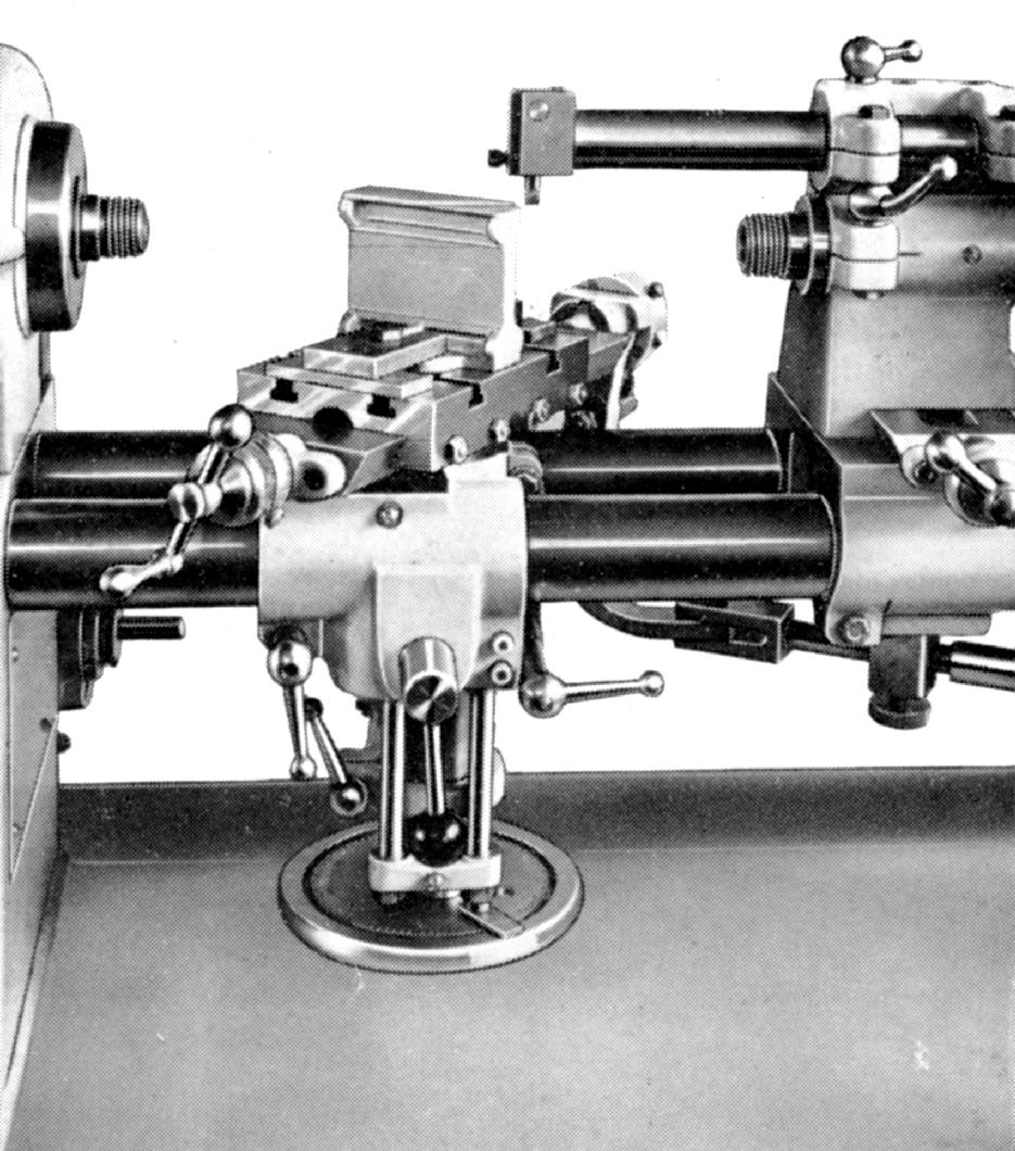
Shaping. The detachable shaping head is shown fitted into its carrier bracket on top of the tailstock. The ingenious use of a cable-operated ratchet feed was used to move the table. |
||
|
Drilling using the indexing and set-over tailstock to space out holes. The unit being drilled has been turned on the lathe and, still attached to its chuck, transferred to the tailstock spindle. |
|
by Kneller Engineering Home Machine Tool Archive Machine-tools Sale & Wanted |
||