email: tony@lathes.co.uk
Home   Machine Tool Archive   Machine-tools Sale & Wanted
Machine Tool Manuals   Catalogues   Belts   Books  Accessories

Rindis Types EF 48/12, EF 50/12, EF52/12 and E.65
Multi-Function Machine
Rindis Rebuild Guide (PDF download)


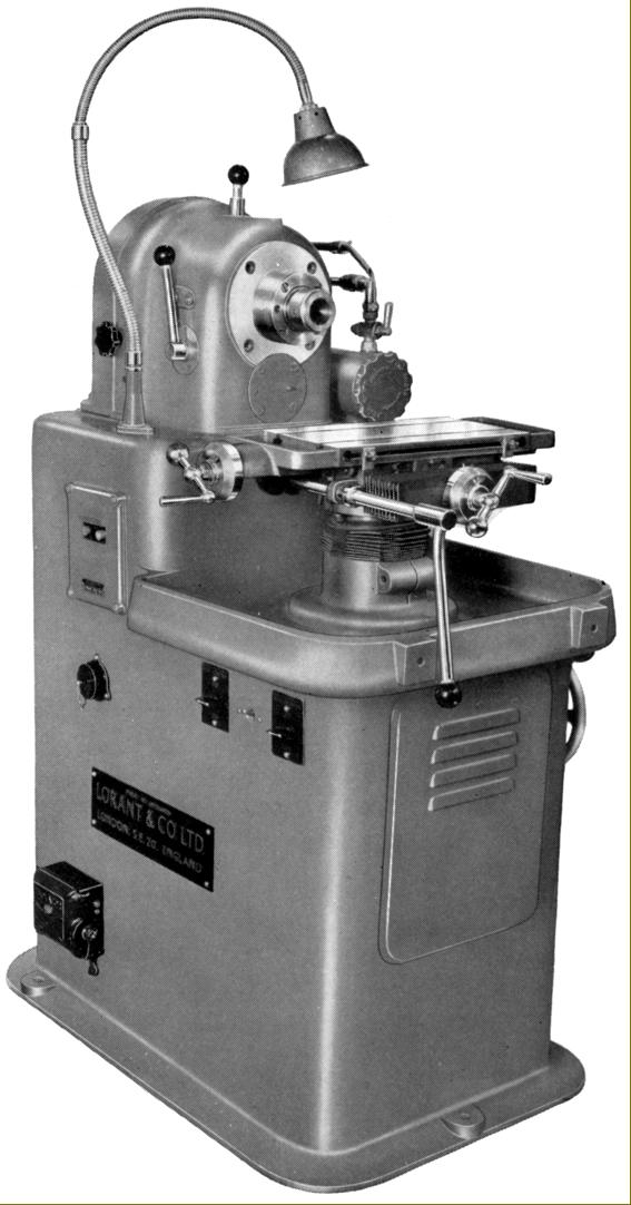
Introduced in 1947, and in production until at least the late 1950s, the heavily-built Rindis was one of those unusual machines that appeared to promise everything - yet never caught on widely enough to become well known. Described as The machine tool with the scope of a machine shop, it was manufactured by Lorant & Co. of  98-100 Croydon Road, London SE20 and today might find a home in the workshop of the keener home-shop machinist, or model engineer, where it would doubtless provide an economical and very compact way of combining several machines in one (yet without the usual size and weight associated with the type). Quite different in every way to that other small, English-made multi-function machine the Scope, the Rindid was protected under British patents 54019, 561216, 577391 and 748101 (and US patent 2376262) the miller appears to have been built in at least two forms, the Mk. 1 and Mk. 2 - the latter version being somewhat beefed up and with a number of minor mechanical modifications. A number of different models were offered being listed as the Types EF 48/12, EF 50/12, EF 52/12 and E.65 - though it's likely that others, as yet undiscovered, would also have been available.
Heavily built, the cast-iron base had built-in switchgear (including an external power socket for accessories and built-in low-voltage lighting) and a front section that held a suds tank and centrifugal pump together with the spiral-gear driven elevation mechanism for the compound table. The rear section contained a swing bracket (with a patented tensioning device) upon which was carried, at first, a 1 h.p. and later a 1.5 h.p. three or single-phase motor drive motor. An ingenious system of V-belts, together with a lathe-like backgear assembly, gave an unusually wide range of eighteen speeds: 80, 100, 130, 150, 170, 240, 300, 340, 345, 430, 440, 565, 620, 720, 1010, 1280, 1820 and 2560 r.p.m. However, by the use of an additional pulley, at extra cost, a further two higher speeds of 2,800 and 3,400 r.p.m. could be obtained. On early models the gear-driven slow speeds were engaged by a push-pull control knob (below and to the left of the spindle nose) but on Mk. 2 models, like the E.65, having a lever set vertically on the headstock's left-hand face. 
With movements by screw, or though the action of a quick-release, lever-operated rack-and-pinion gearing, the 12.5" x 6.5" compound table could be fed longitudinally through  7.5" and across by 5". The feed screws were fitted balanced handwheels and large diameter micrometer collars engraved at intervals of 0.001". In addition, the table could both be swivelled through 360 degrees and caused to rise and fall by the use of a handwheel on the right-hand side of the cabinet stand.
Hardened and ground, the nickel-chrome steel hollow spindle ran in tapered roller bearings and had a front register machined to take direct-fitting collets of up to 1-inch through bore. The nose was threaded to accept the usual chucks and faceplates (a useful lock was fitted to ease the fitting of accessories) while the front of the headstock (around the spindle mounting) was machined with two registers to mount certain of the accessories.
Weighing approximately 8 cwt. (406 kg) in its early form and later 10.5 cwt. (533 kg) the Rindis stood on a base that held a coolant tank 20" wide and 31" front  to back.
A number of useful accessories were available, some necessarily expensive, that allowed the Rindis to be used for surface, cylindrical and cutter grinding; vertical and horizontal milling; slotting; turning, boring, simple second-operation and cut-off lathe work; drilling; sawing, cutting off and disc filing, etc. In addition to those illustrated below, others included: a 7-inch band-saw to take spiral and flat blades; a set of nine collets and a retaining compression nut for direct fitting in the main spindle: ¼", 5/16", 3/8", 7/16", ½", 5/8",, ¾", 7/8" and 1"; a tungsten-tipped parting-off tool, various cup and standard grinding wheels and slitting saws; a diamond dressing tool and mount; Lorantco vices Type CV-1 centring for holding round bar stock and Type CV-2 for flat sections; ; an adapter to mount the turbine-driven air grinder, a circular magnetic chuck and backplate for spindle mounting; a de-magnetiser Type DA;  a Lushington Boring head No. 0 with a No. 2 Morse taper mount; a magnetic swarf separator for the coolant supply; a tap regrinding and relieving fixture;  a set of gaiters to protect the table rising and falling support column and the compound slide; an inspection lamp with to plug into the side-mounted power socket; machined backplates for the headstock spindle; collets with a No. 1 and No. 2 Morse taper bore and two accessory cabinets, one 17" x 15" x 33" that was demountable and another 33" x 18" x 46" that was permanently-mounted.
Should any reader have a Rindis (they are now very rare), the writer would be interested to hear from you.
A Rindis rebuild guide is here as a PDF download

Late Mk. 2 Model Rindis E.56 in basic form. The handwheel on the right-hand side of the machine operated the compound table rise-and-fall.

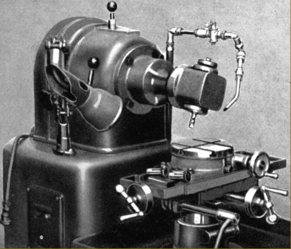
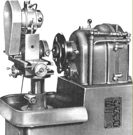
An earlier Mk. 1 Rindis, believed to have been introduced during 1948, the Type  EF50/12

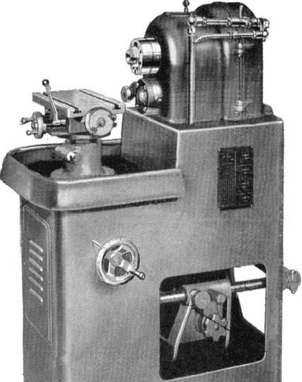
Rindis EE50/12 fitted for conventional horizontal milling. This version of the horizontal attachment has one overarm - another improved type, with two, (shown below) was also made.

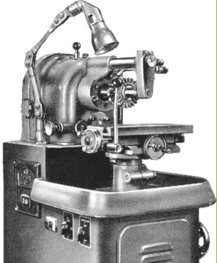
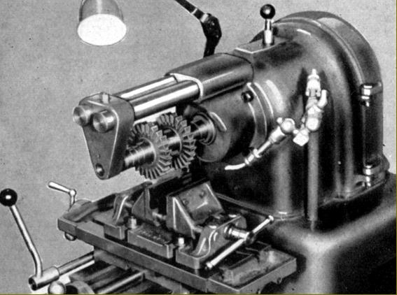
Horizontal milling (Part No. 22)
Bolted to a machines flange surrounding the headstock spindle, the horizontal milling attachment consisted of a heavy casting from which protruded two steel bars. The 1-inch diameter cutter arbor was in nickel-chrome steel and supplied complete with the necessary hardened an ground spacing washers. Cutters up to 5-inches in diameter could be mounted.

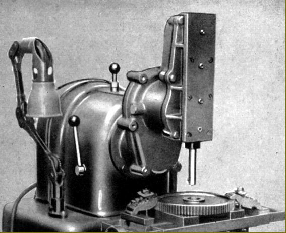
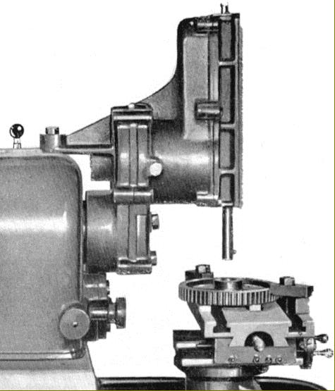
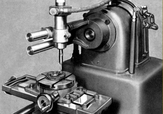
Vertical Milling Head (Part No. 23) and Rotary table (Part No. 30)
Engraved with a degree scale around the periphery of its mounting flange, the vertical milling head could be swivelled though 90° each side of upright. The spindle was bored No. 2 Morse taper  and accepted direct fitting collets. However, there was no quill feed, all vertical movements being accomplished by lifting the table. Included with the head were ¼", 3/8" and ½" direct-fitting collets.


Jig Boring
By using the vertical milling attachment and rotary table and fitted with a micrometer boring head on a collet fitting, the Rindis was capable of undertaking simple jib boring operations

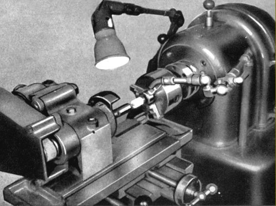
Internal Cylindrical Grinding with a Lorantco Tool & Cutter Grinder (Part No. 20) and 3-Jaw chuck (Part No. 2)
Mounted on the compound table, the cutter grinder had speeds of up to 11,000 r.p.m., sufficiently high for the use of the tiny stones on the end of internal grinding spindles.

Slotting Attachment (Part No. 19)
With built-in reduction gears, the slotting attachment had a stroke of 3 inches.

Slotting head cutting a keyway inside a gear

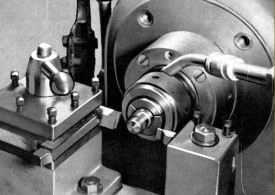
Lorantco dividing head and tailstock (Part No. 31)
Built from Meehanite castings with a ground, nickel-chrome hollow No. 2 Morse taper spindle able to take collets up to 1/2" bore and threaded on the end to mount chucks, the centre height of the dividing head was 2".

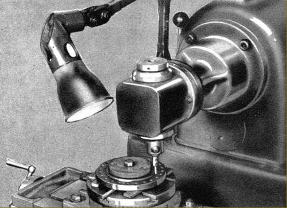
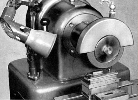
Lorantco Tool Post Grinder (Part No. 20)
Used for cylindrical grinding, the Lorantco unit bolted to the swivelling compound table and could be set to cut both tapers and parallel jobs. grinder was supplied complete with a ¼ h.p. 3-phase motor and three external and three internal grinding wheels.

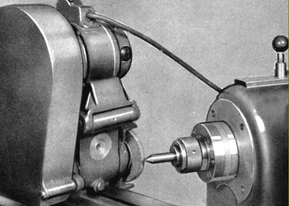
Rindis with the tool-post grinding unit mounted

Lorantco High-speed Routing Attachment (Part No. 28) with mounting bracket (Part No. 29) and Rotary Table (Part No. 30)
Mounted on the same 2-bar bracket used for the horizontal milling, the router contained an air-driven turbine running at speeds from 20,000 to 40,000 r.p.m. The unit could be fitted with the usual sort of miniature cutters -  engraving tools, end mills, slot drills and carbide burrs, etc.

Front Indexing 4-way toolpost (Part No. 45) with 4-way indexing, Parting Off Toolpost (Part No. 11) and Collets (Part No. 4)
Fitted with these parts the machine could be used for second-operation work or form turning

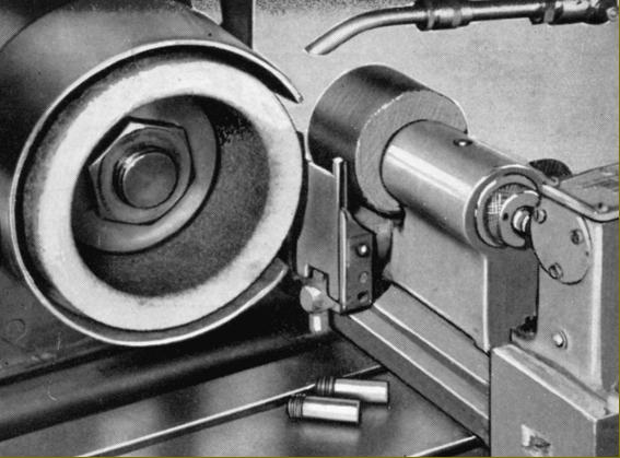
Surface Grinding Arbor, spindle Extension and Guard (Parts No. 53, 3 and 54) and Eclipse 7" x 5" Magnetic Chuck (Parts No. 38, 38a and 39)

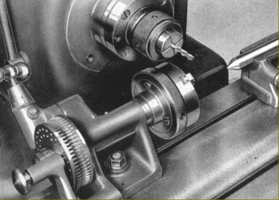
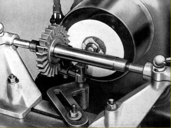
Cutter Grinding Centres and Index Finger (Part No. 41) and Arbor (Part 22)
Fitted with these components the Rindis could be pressed into use as a tool and cutter grinder

Centreless Plunge Grinding Attachment (Part No. 48)
Fitted with this unit the Rindis could undertake short-run production work on diameters up to 1.5" with the length set by the wheel width (usually 3")

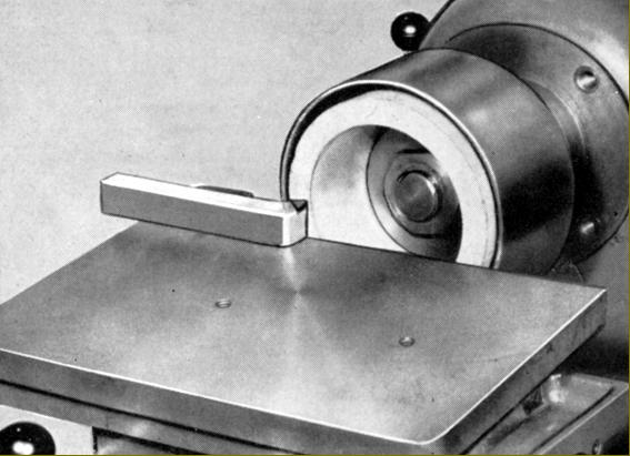
False tilting table (Part No. 34), Grinding Wheels, Arbor and Guard (Parts Nos. 13 and 14)
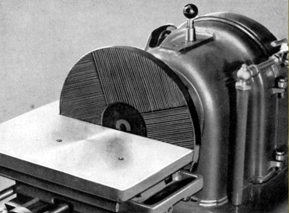
Ideal; for sharpening lathe tools, this attachment protected the ground surface of the tilting compound table (hence "false") and could be tilted to the required angle

Disc Filing
The patented double-sided Rindis filing discs were intended for the rapid removal of material yet with an exceptional good surface finish. The discs could be sharpened up to fifteen times and were intended to be run at speeds not exceeding 400 r.p.m.
Rindis also supplied special bench and floor-standing version of the machine devoted exclusively to the use of these wheels. The floor versions had a circular compartment on the left hand face of the column to store spare discs.

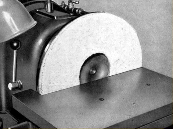
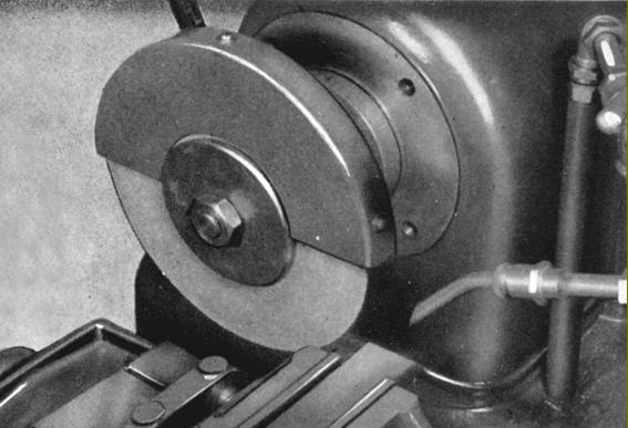
Disc Grinding and sanding Attachments (12-inch backplate Part No. 1a and 36, 12-inch heavy-duty grinding discs Part No. 7 and 12-inch emery discs Part No. 5)

Abrasive Wheel Cutting-off wheel (Part No. 17) with Guard (Part No. 3), a Lorantco Type CV-2 Precision Vice (Part No. 33) and Spindle Extension (Part No. 15)


email: tony@lathes.co.uk
Home   Machine Tool Archive   Machine-tools Sale & Wanted
Machine Tool Manuals   Catalogues   Belts   Books  Accessories

Rindis Types EF 48/12, EF 50/12, EF52/12 and E.65
Multi-Function Machine