 |
|
|
|
|
|
|
|
|
|
|
|
|
|
|
|
|
|
|
|
|
|
|
|
|
|
|
|
|
|
|
|
|
|
|
|
|
|
|
|
|
|
|
|
|
|
|
|
|
|
|
|
|
|
|
|
|
|
|
|
|
|
|
|
|
|
|
|
|
|
|
|
|
|
|
|
|
|
|
|
|
|
|
|
|
|
|
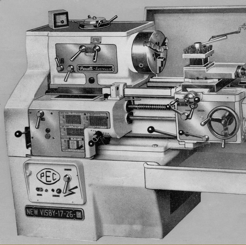
Last in a long line of New Visby and Visby lathes (the first of the latter dating from the early 1920s) the New Visby Mk. 3 was a complete departure from earlier designs and introduced in 1959. No longer intended to satisfy the just the garage, general repair workshop and light production markets, the new lathe was entirely redesigned with serious industrial use in mind - improvements included a very much heavier build, a motor several times as powerful as before, a vastly improved speed range and positive lubrication to headstock, screwcutting gearbox and apron. In many, if not all respects, it was able to compete with the very successful and similar-sized Colchester Triumph 2000 introduced a few years later. Like Colchester, Purcell offered a "toolroom" class version of the lathe, though one suspects that this, like the English machine, was not specially built but merely selected from an ordinary batch as being the most accurate.
Continued below:
|
|
|
|
|
|
|
|
 |
|
|
|
|
|
|
|
|
|
|
|
 |
|
|
|
|
|
Continued:
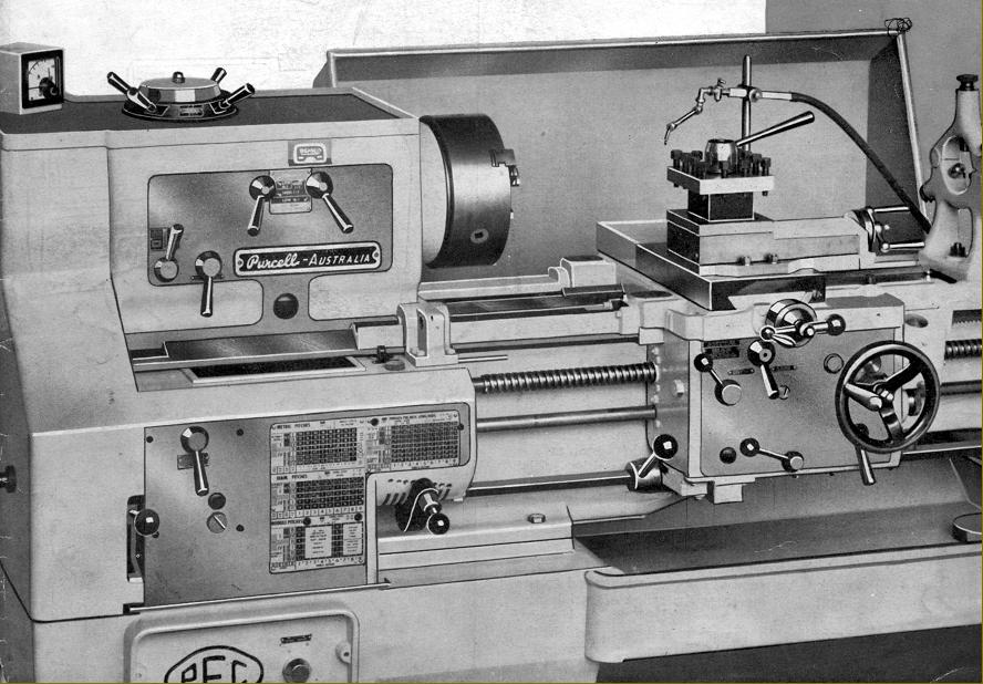
Of 8.5" centre height, and available with 48, 78, 103 or 123 inches between centres, the lathe had an especially deep bed - and even deeper when fitted with the optional 26-inch capacity gap - braced by heavy box-section ribs. The massively constructed headstock end support pedestal was extended towards the tailstock, to ensure the gap section was fully supported - whilst longer-bed versions had a middle plinth for additional rigidity. Both supports were fitted with externally mounted bolts by which means the lathe could be levelled. Unlike early Visby types, which used an all-V-way, ground-finish guide system for the saddle, the Mk. .3 - with a bed hardened by heat treatment - employed the more common method of a V at the front (wide and shallow on its outer surface and narrow and steep on its inner) and a flat at the rear.
Continued below:
|
|
|
|
|
|
|
|
|
|
|
|
|
|
 |
|
|
|
|
|
 |
|
|
|
|
|
|
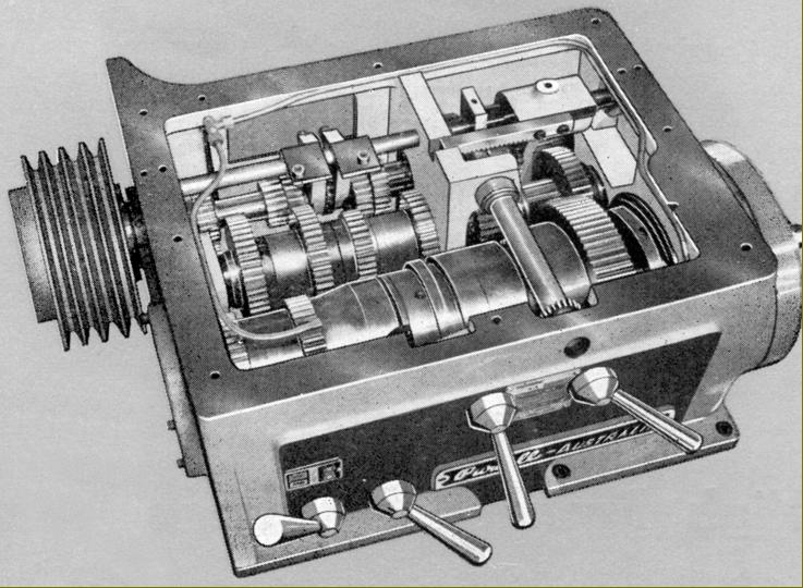
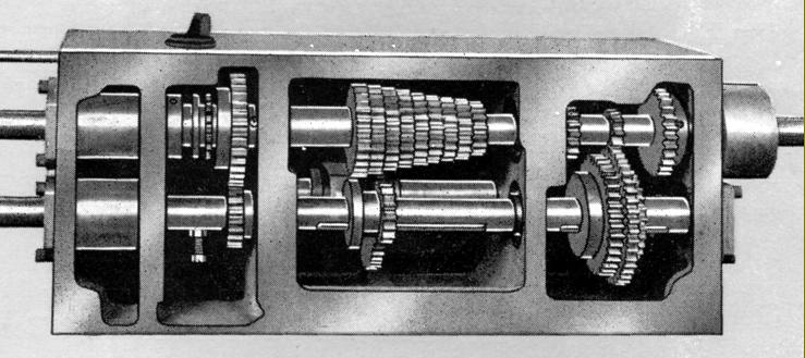
New Visby Mk. 3 headstock internals
Continued:
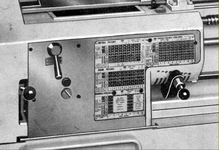
Fitted with a hardened, short-flange, American Standard 8A1 spindle nose, the 3.125-inch bore spindle ran in a pair of pre-loaded, precision-class Timken taper-roller bearings at the front and a conventional precision taper-roller bearing at the rear. Although the chosen spindle nose did reduced overhang, obtaining and fitting alternative chucks and backplates would always have involved much extra work. As a thoughtful touch - bearing in mind the relatively huge size of the spindle in comparison to the centre height - the makers included an adjustable steady guide at the outer end of the spindle bore so that small diameter workpieces could be supported and prevented from flinging. The drive system used a base-mounted, 10 h.p. motor coupled to the headstock input pulley by four B-section V-belts. The pulley ran its own bearing set, so isolating the drive shaft from the considerable bending stresses of the belts. Fitted on the centre shaft and running immersed in oil, was a powerful combined multi-disc clutch and brake assembly with control by a third-rod system the operating lever of which was pivoted from the apron's left-hand face. An Ampere-meter was fitted, to show the operator how hard the machine was working - whilst the buyer was offered a choice of three speed ranges: 18 to 1000; 22 to 1200 and 27 to 1500 r.p.m. Each range had its higher speeds significantly increased over anything offered before by the maker in this class, with changes made by the juxtaposition of two levers on the face of the headstock and a dial on the top - selection of an appropriate speed being aided by colour coding of the positions. However, as on many other lathes of the same era, there was no spring-loaded or other type of safety interlock to prevent the controls being accidentally nudged into expensive (and possibly dangerous) engagement. Control of the spindle stop and start was by a third-rod system, with the control lever pivoting from the left-hand face of the apron.
All headstock gears were hardened and ground, as were their shafts, which turned exclusively in either ball or roller races. Lubrication was partially by splash and partially by pressure pump, a sight-glass and flow window being provided to check that the system was working correctly.
Continued below:
|
|
|
|
|
|
|
|
 |
|
|
|
|
|
|
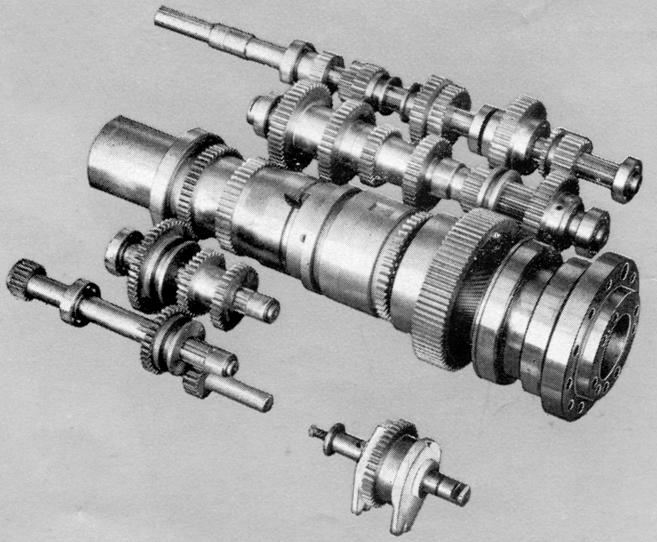
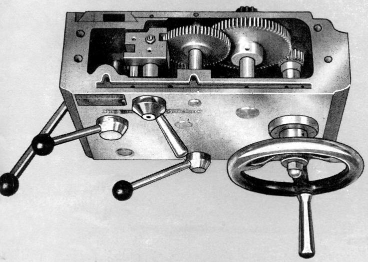
Screwcutting and feeds' gearbox
|
|
|
|
|
|
|
|
|
|
|
|
|
|
 |
|
|
|
|
|
|
Screwcutting gearbox internals
Continued:
Able to generate 72 inch pitches from 4 to 60 t.p.i and 66 metric from 0.25 to 120 mm pitch without altering the changewheels, the screwcutting and feeds gearbox had gears supported on shafts running in ball or roller bearings and lubricated by splash from an oil sump. Reversible when worn, of 13/8" diameter and 2 t.p.i., the leadscrew was held in tension, ran in ball races and was only used when screwcutting - a mechanism being provided that automatically disengaged the drive (either screwcutting or by power feed) should the saddle get too near the headstock. Longitudinal (sliding) feeds - driven by a separate power shaft - ranged from 0.001" to 0.344" with the cross-feed rate set to be twice as fine. Adjustable knock-off stops were offered as an option on the cross feed, but details of how these worked, of if indeed they made it into production, are unknown.
Continued below:
|
|
|
|
|
|
|
|
 |
|
|
|
|
|
|
New Visby Mk. 3 double-wall oil-bath and pressure lubricated apron
Continued:
Totally enclosed, the double-wall apron held a supply of oil within its base from which lubricant was distributed by a pump, though this was not, unfortunately, extended to the lathe bed or cross-slide ways. Designed along the lines of the apron first seen on the 8.5-inch "heavy-duty" version of the New Visby, power-feeds were engagement by an instant-action drop-in-and-out worm box with the addition of a clutch to protected the mechanism against overload. As an additional - and very useful facility - it was possible to reverse both feeds from the apron without needing to stop the drive first.
Continued below:
|
|
|
|
|
|
|
|
 |
|
|
|
|
|
|
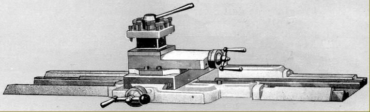
The saddle was fitted with four exceptionally long bed-way covers
Continued:
As on the previous incarnation of the New Visby, extra-long bed-way covers were bolted to each end of the saddle's wings. As the bed ways ran on past the front and rear faces of the headstock, the covers (fitted with felt wiper on their mounting flanges) provided protection for the full extent of the most frequently used operating positions.
Fitted with tapered gib strips and balanced handwheels (that on the 360° swivel top slide of the shortened, double handle type) the cross and top slide assembly had Acme-form feed screws that ran through bronze nuts with ball-bearing support where they passed though the end plates. The ordinary cross-slide was of the short type, to permit the mounting of a taper-turning or hydraulic-copy attachment, but available at extra cost was a worthwhile full-length slide that, besides spreading wear more evenly over the ways, allowed the fitting of a rear toolpost for parting off and forming work. Micrometer dials were of a decent size, with a narrow knurled ring to aid grip, and a steel 4-way toolpost, of considerable depth but only one-way indexing, was fitted as standard.
Continued below:
|
|
|
|
|
|
|
|
|
|
|
|
|
|
 |
|
|
|
|
Continued:
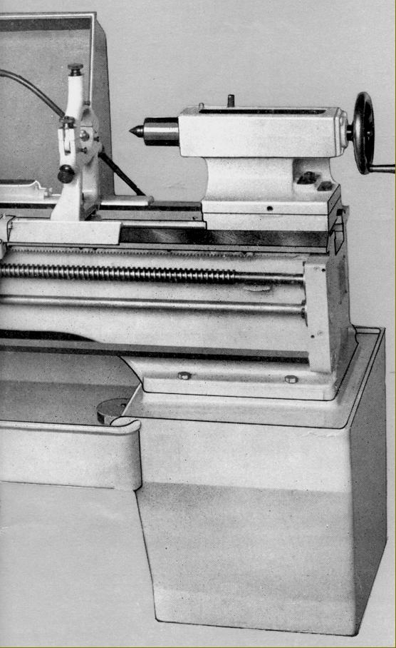
Although another version this lathe, sold as the No. 17/26-11 Record, was fitted with the earlier type of rounded-style tailstock, that on the No. 17/26-111 New Visby was of a much heavier construction with a properly hardened and honed-to-fit 2.875" diameter spindle with a huge No. 4 Morse taper (with tang socket) and 7.75 inches of travel. Clamped to the bed by the usual over-centre locking lever, the unit could be set over for the turning of slight tapers and the sole plate fitted with felt wipers.
A decent range of equipment was supplied with each lathe: a 10 h.p. motor and all the electrical control gear; fixed steady, travelling steady, 4-way toolpost; an electric coolant pump, tank, distribution pipework, slide-out chip tray and splash-back; 17-inch faceplate, catchplate, Morse taper centres and a headstock reduction sleeve (this will be missing from a used lathe); thread-dial indicator, metric-conversion changewheel set and a spindle safety steady for working with small bars..
|
|
|
|
|
|
|
|
 |
|
|
|
|
|
|
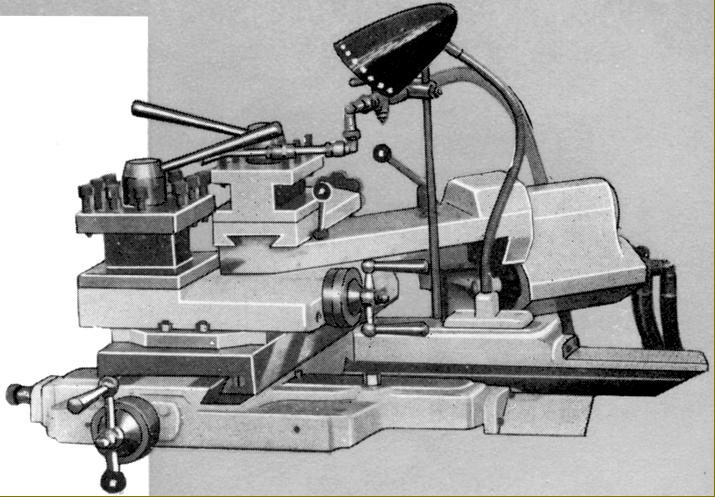
New Visby Mk. 3 hydraulic-copy attachment
|
|
|
|
|
|
|
|
 |
|
|
|
|
|
|
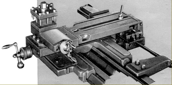
New Visby Mk. 3 taper-turning attachment had a 15" length capacity of up to 15" in length and 16° in
|
|
|
|
|
|
|
|
|
|
|
|
|
|
 |
|
|
|
|
|
|
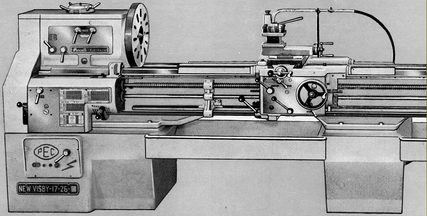
New Visby Mk. 3 long-bed version with central bed-support plinth
|
|
|
|
|
|
|
|
 |
|
|
|
|
|
|
|
|
|
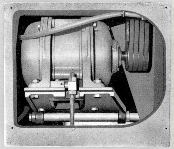
Motor on its adjustable mounting plate with the drive taken off by four B-section V-belts
|
|
|
|
|
|
|
|
|
|
|
|
|
|
|
|
|
|