email: tony@lathes.co.uk
Home   Machine Tool Archive   Machine-tools Sale & Wanted
Machine Tool Manuals   Catalogues   Belts   Books  Accessories

Mitsui Seiki Jig Borers Japan
Home Page & No.5A

Mitsui No.0, No.1C Jig Borer & Jig Borer Accessories  Mitsui No. 3A Jig Borer
   
Mitsui Jig Borer 4B  Mitsui Jig Borer 6A  Mitsui Jig Borer 7B 

Mitsui Jig Borers 4DN, 6CN, 7CN

Mitsui Seiki Full Production Range 1980s

Mitsui Jig Borers 3E, 4BMD, 4DN, 6CM, 6CN, 6BD, 7CM, 7BD and 7CN
Mitsui Seiki Jig Borers,Jidic 7N, No.0, No.3, No.5 and No.6
Precision Measuring Instruments MLA-250, MLB-2000, UMC-1000 and UMD-1000
Grinding Machines MUG27. MUG 50/27 and MUG 75
Leadscrew Measuring Machine, Electronic Indicator and Rotary Tables

Catalogue Sets are available for Mitsui Jig Borers & other Machine Tools


Established in 1928 to give Japan a home-based maker of high-precision machine tools, today the Mitsui Company continues that tradition and offers an up-to-date selection of jig borers, jig and thread grinders and advanced vertical and horizontal CNC machining centres built in a state-of-the art factory in Kawajima, Japan.
In the 1920s, although capable of manufacturing complex mechanical items, Japan lacked one vital resource, a company with the ability to manufacture ultra-high precision measuring instruments. Without a home-based industry of such items as micrometers, Johansson gauges and precision measuring apparatus, Japan had to rely on expensive imports, thus limiting the extent to which smaller engineering firms could improve the range and quality of their products.
A country established for many decades as a leader in this highly specialised field was Switzerland from where, in 1862 the Geneva-based 
Société Genevoise d'Instruments de Physique began producing scientific apparatus, precision measuring instruments and jig borers. Although the French-based International Bureau of Weights and Measures kept the "master metre" bar and two witness bars in their vaults, they appeared unable to provide subdivided replicas to National Governments. Hence, SIP was called upon to produce working standards for the International Bureau, the Bureau of Standards in Washington and the National Physical Laboratory in Teddington, England (and other important metrological institutions). The initial result was a very high precision steel ruler -  a standard scale - by which other length-measuring instruments could be calibrated, these being sold in considerable quantities to Government, engineering, scientific, military and metrological institutes worldwide
Having copied the Swiss approach to metrology, by 1928 Mitsui had introduced sets of bock gauges, limit gauges and micrometers; in 1933 came their first Universal Measuring Machine (similar in concept to those made by Pratt & Whitney and SIP); in 1935 their first Circular and Linear Dividing Machine (a contemporary example by SIP can be found on this page) a jig borer, a high-pressure compressor and, in 1940, a cylindrical grinder. In subsequent years other conventional machines were introduced including improved versions of the Precision Measuring Instrument, Universal Co-ordinate and Leadscrew Measuring machines (the latter with an automatic recording facility), gear measuring and inspection equipment, additional models of cylindrical grinder, an optical compound table and a range of standard and tilting rotary tables, some with the option of optical positioning.
Mitsui's first medium-sized jig borer, the No.4 of 1935, was a machine based closely - and why not? - on the highly successful SIP machine of the same size. This was a significant achievement, a machine of this size being large enough to allow other machine tool builders, of whom there were few at the time in Japan, to manufacture even more accurate products, expand their product ranges, give home industries the machines they need for expansion while also matching the standards of foreign competitors.
By the 1960s the range of jig borers was well established with a wide range of models on offer as the No.0, No.1, No.1, No.3, No.5, No. 6 and No.7. By the 1970s and into the 1980s, these had been updated as the 1C, 4B, 6A, 7B and a range of NC and CNC models including the 4DN, 6CN and 7CN. From the early 1980s onwards, the range was modified and expanded to include the 3E, 4BN, 4BMT, 4BMD, 4DN, 6CM, 6CN, 6BD, 7CM, 7BD and 7CN, the basic specifications of these machines are shown on this page and more details of the NC machines into the 1980s here.
The NC-Series models began as early as 1962 with the Model 7N, a semi-closed loop machine, this being followed until 1972 by other with the same control system, the 1963 4BN, the 1967 6BN, and the 1972 7BN. Fully closed-loop machines began in 1972 with the Model 6BNH, this being followed in 1975 with the 4CN, in 1979 with the 7BNH, in 1980 by the 4DN and in 1981 the 6CN and 7CN.
To ensure that their machines met international standards, random sets of scales from the jig borers were sent for calibration and checking to various well-established testing authorities including the National Physical Laboratory of Great Britain and the National Bureau of Standards in Washington. A sample chart from the USA Bureau is reproduced below, the tests all being conducted at 20°C (68°F), the temperature of the room in which jig borers and other very high precision machine tools are meant to be housed.
Continued below:


Continued:
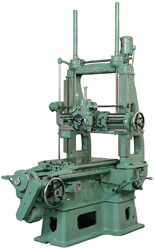
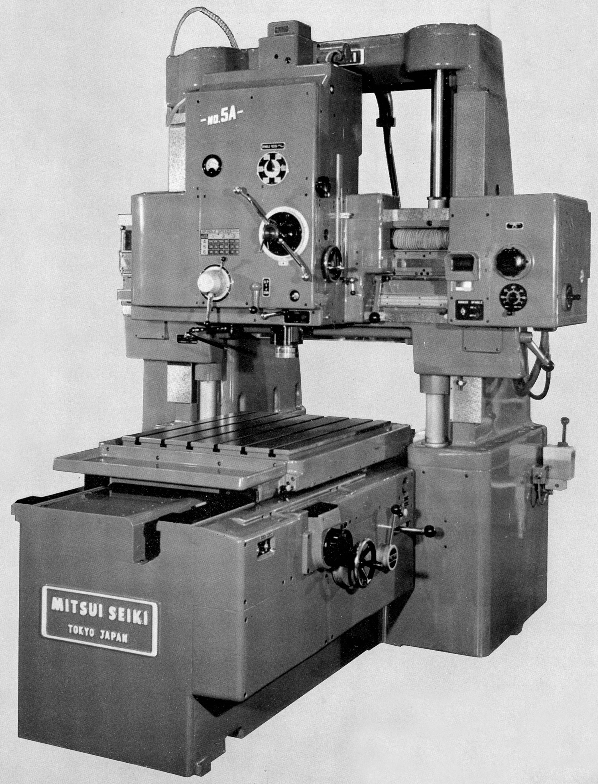
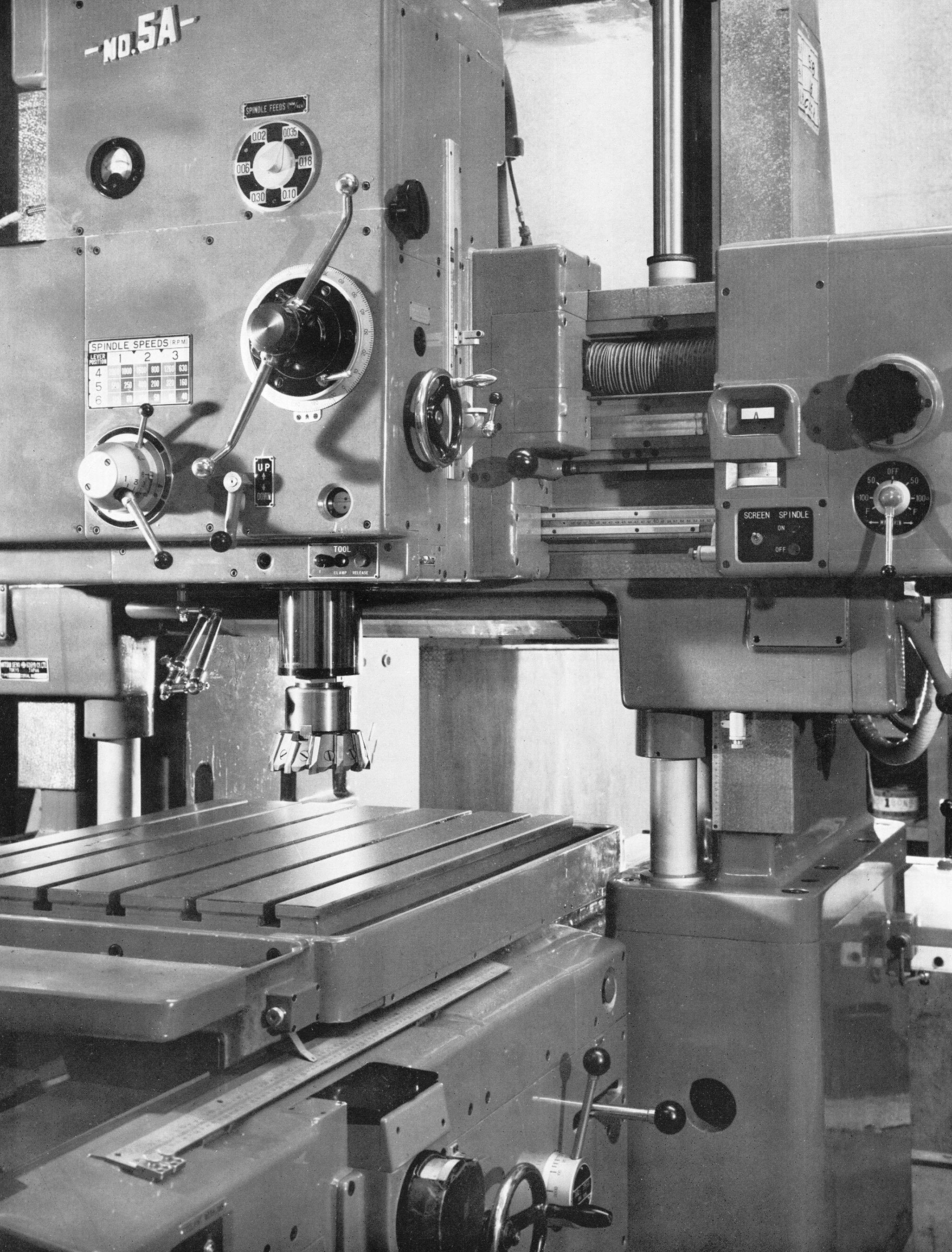
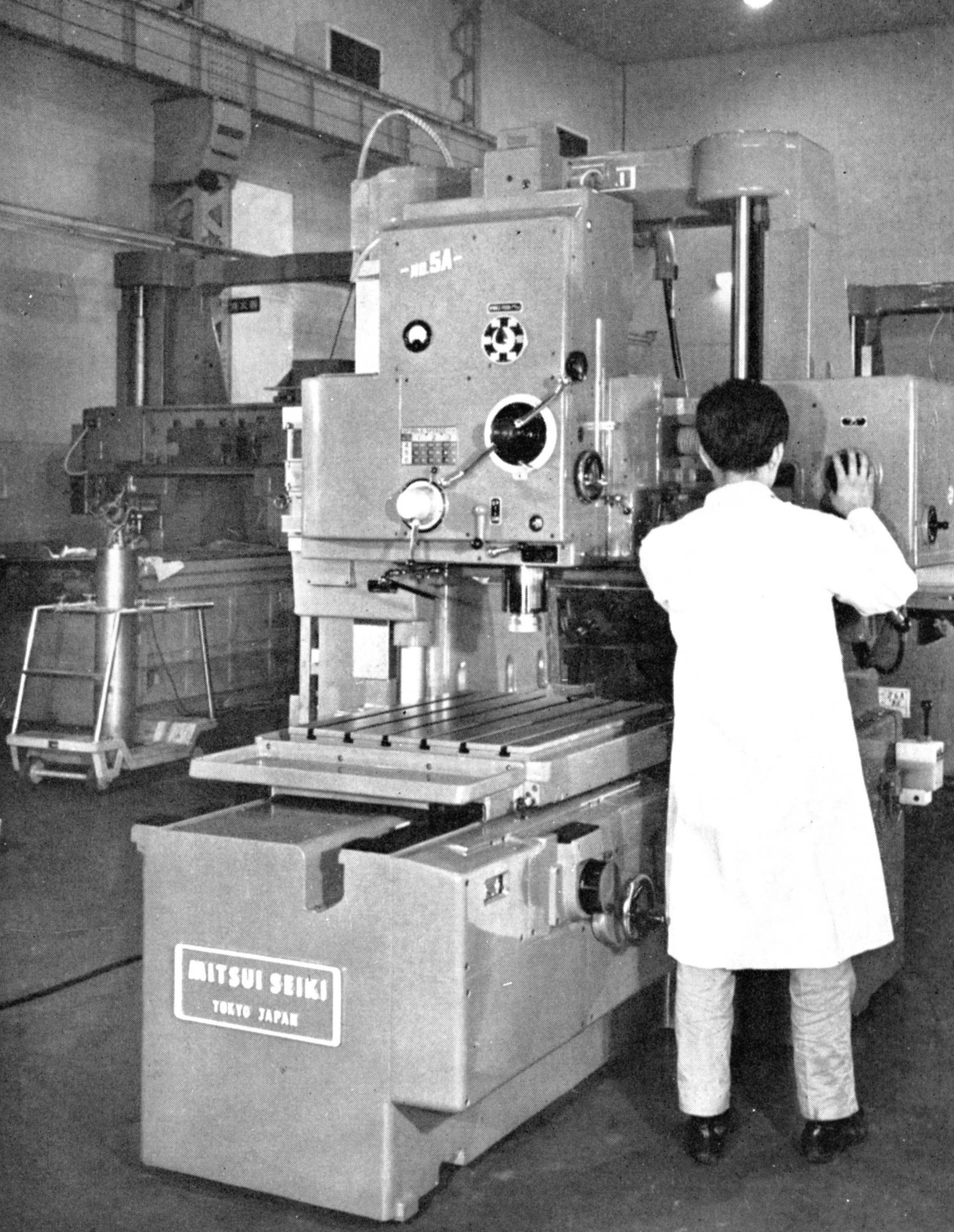
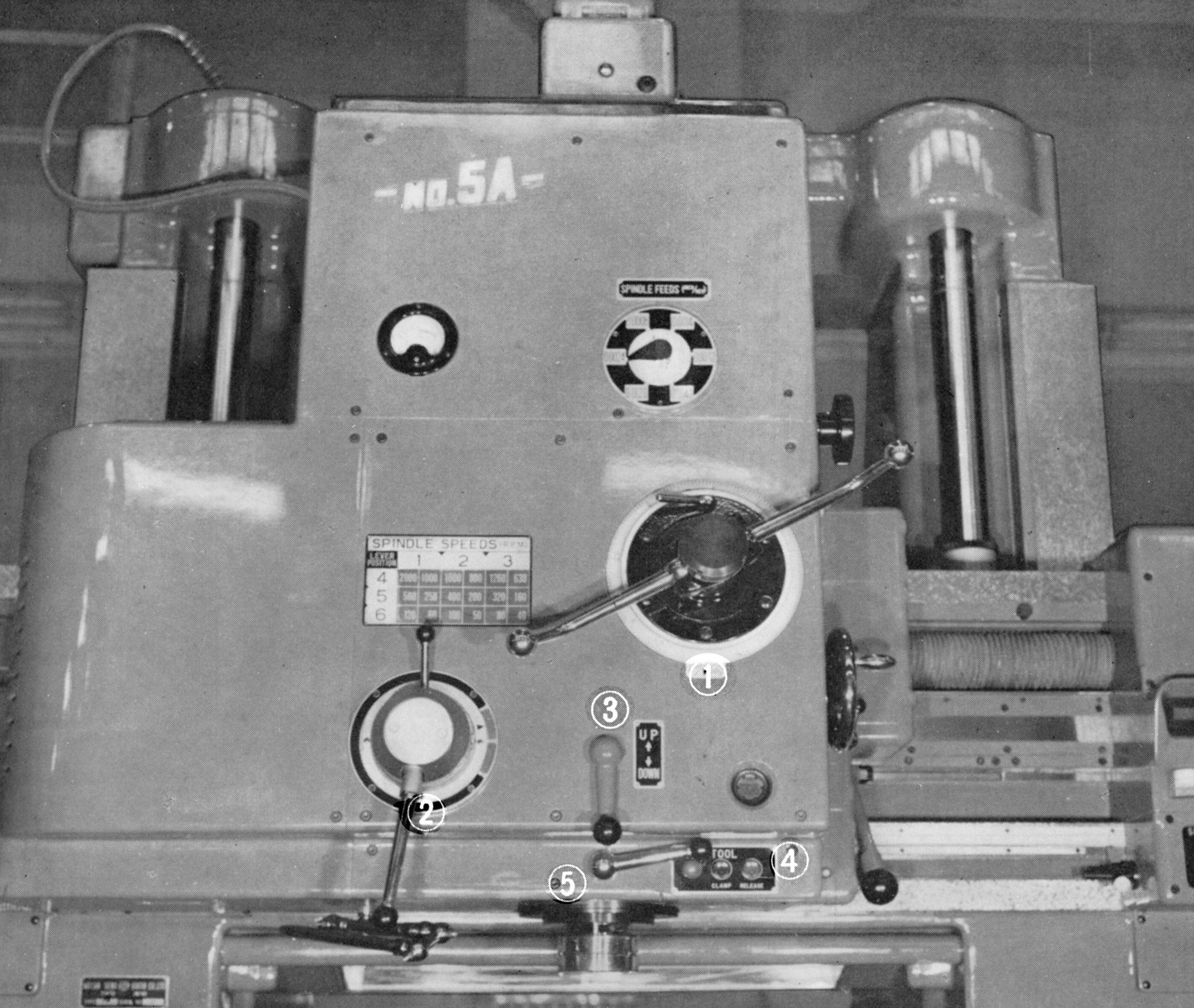
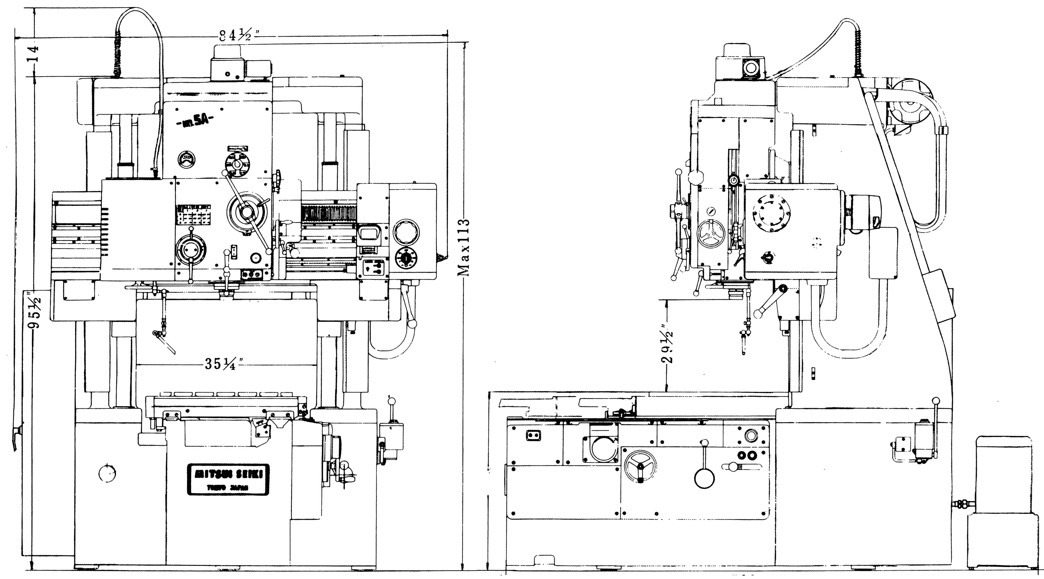
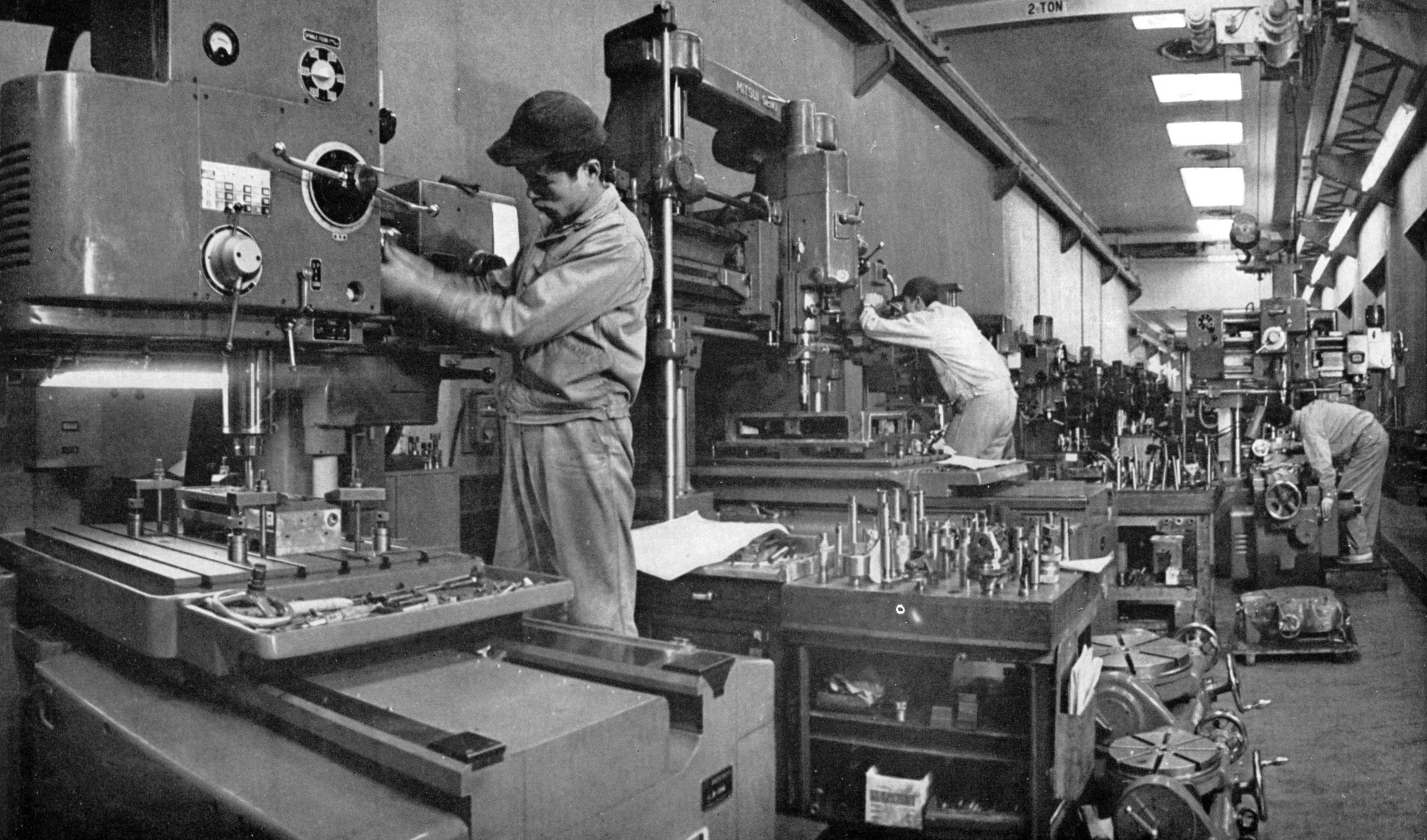
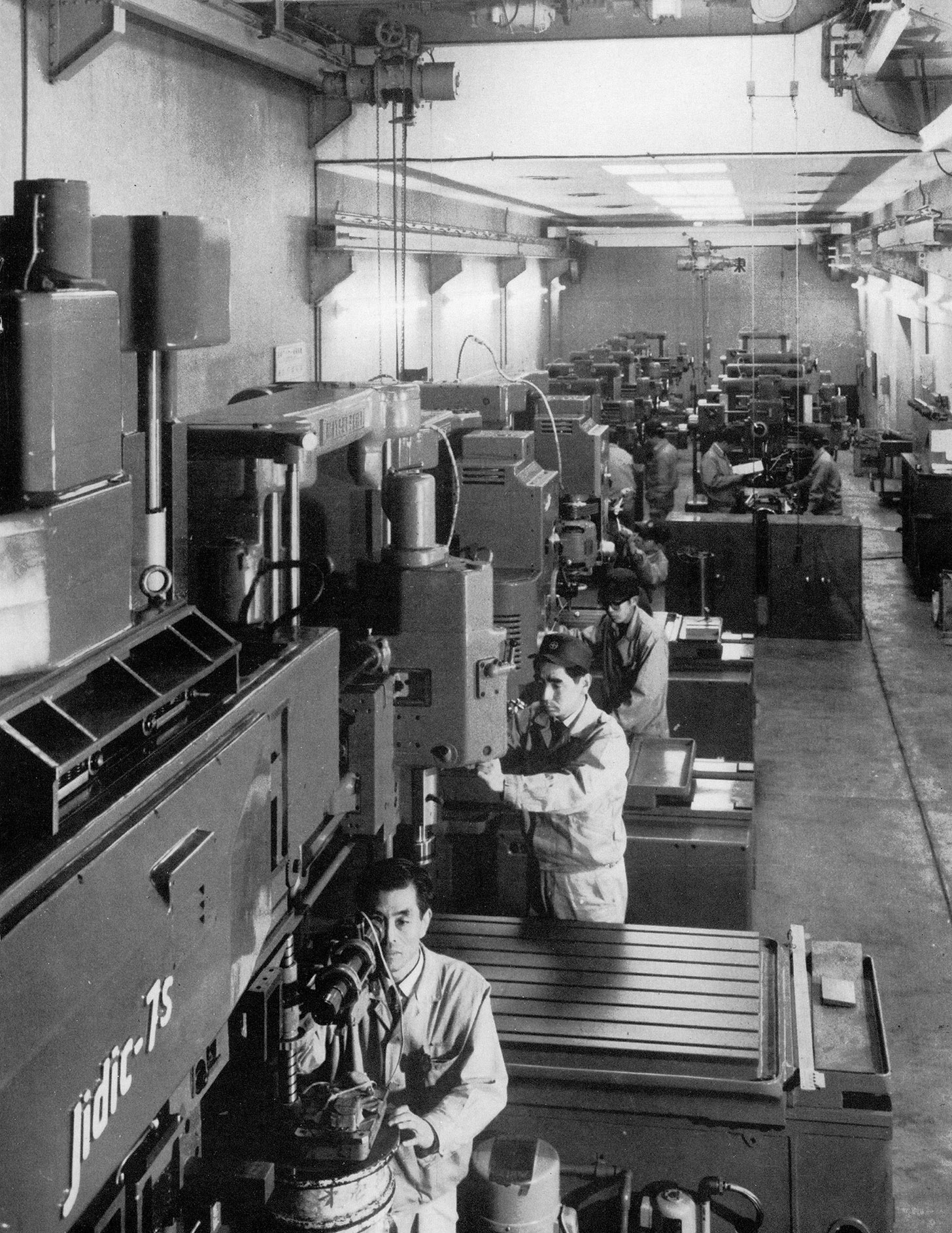
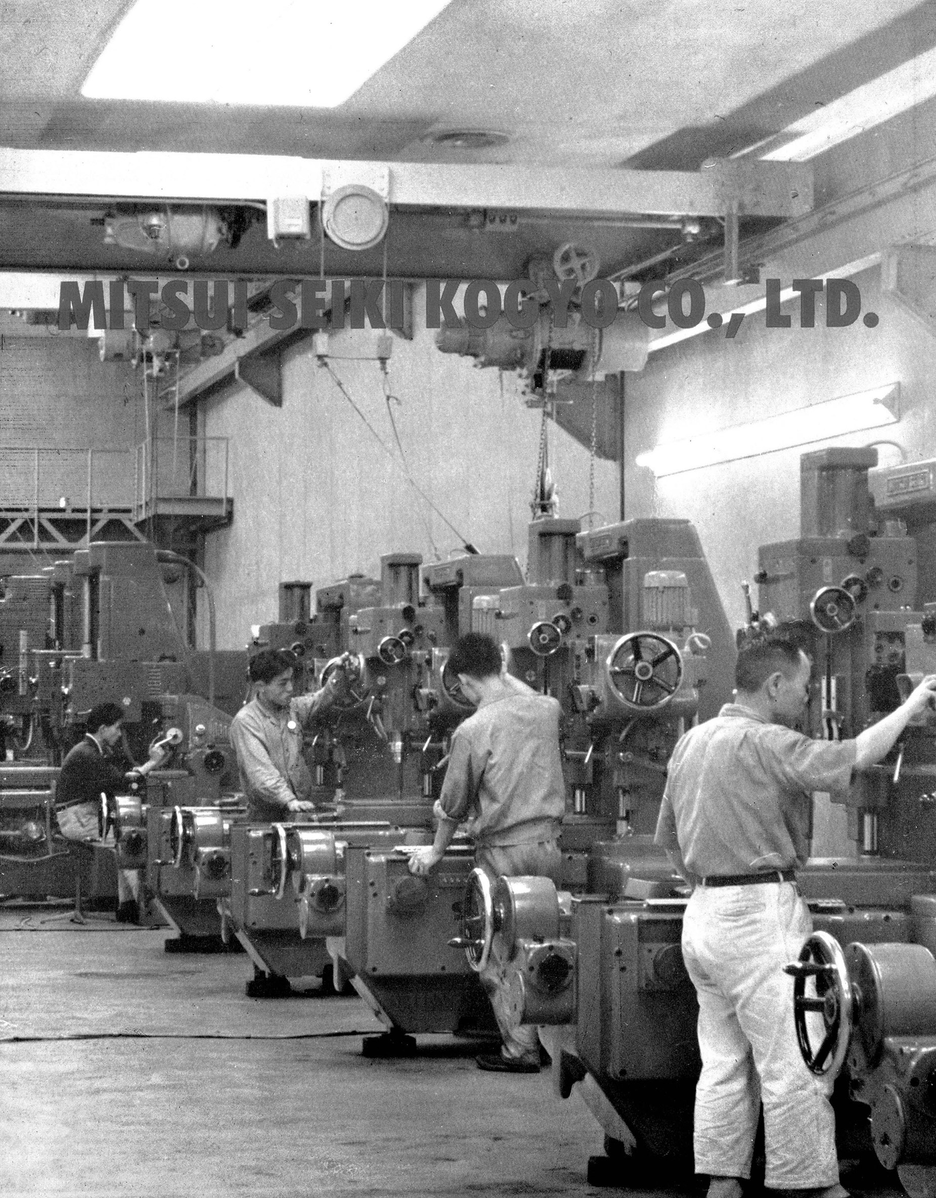
Mitsui 5A Jig Borer of the late 1950s and 1960s
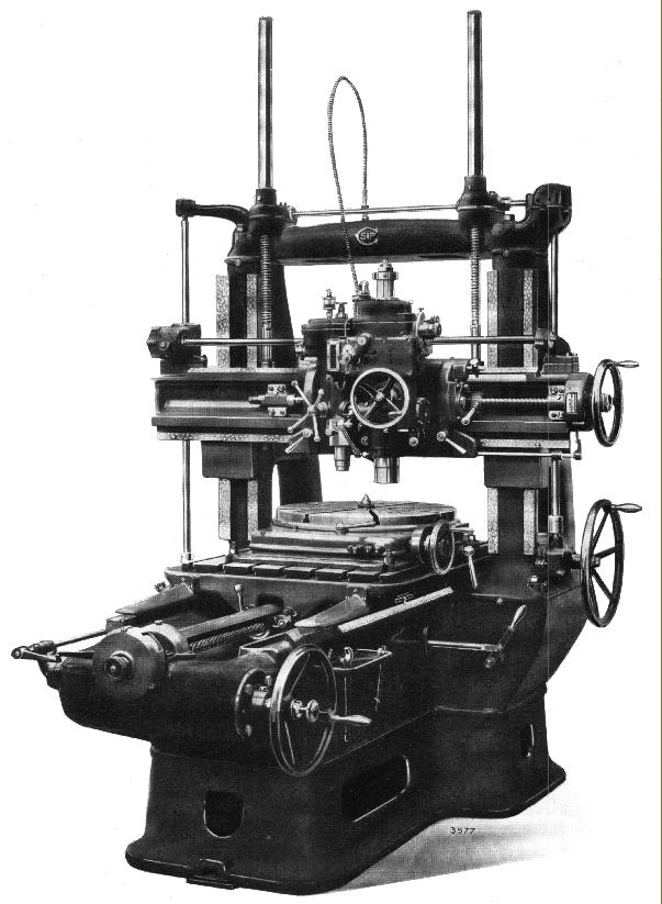
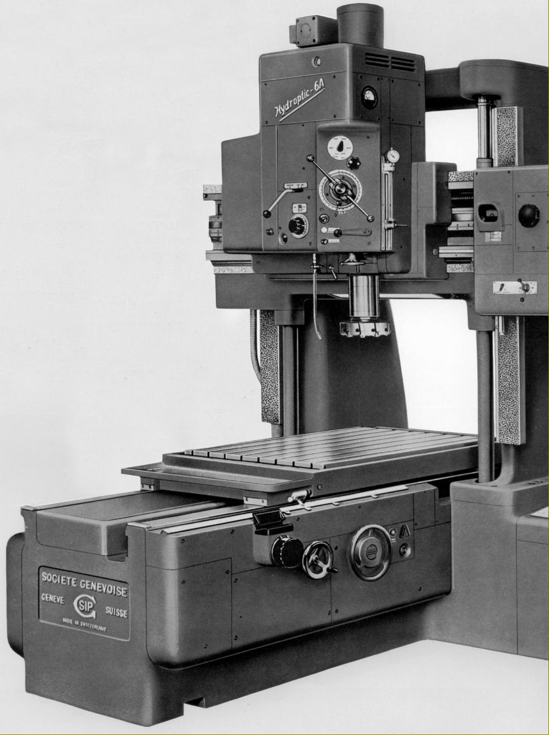
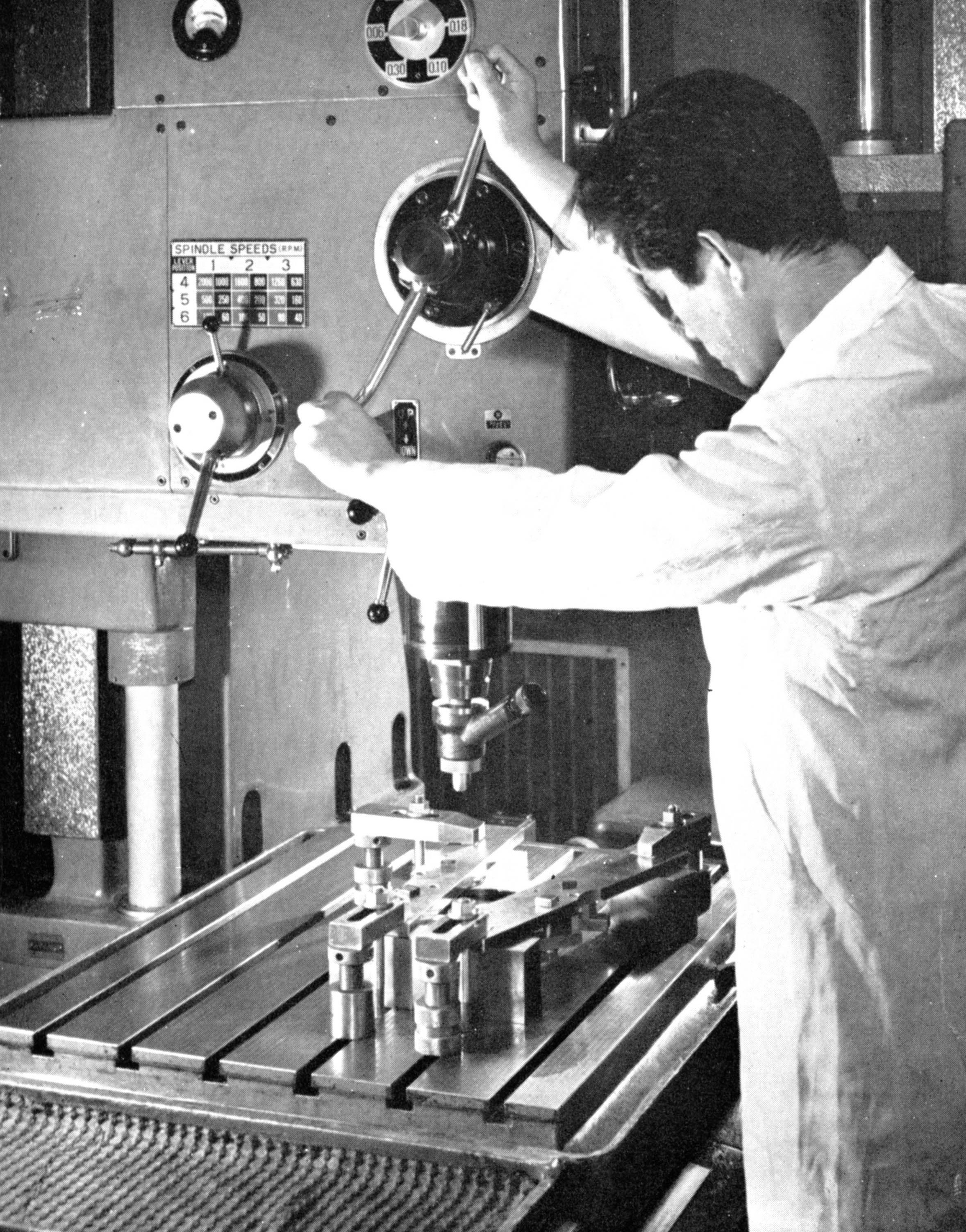
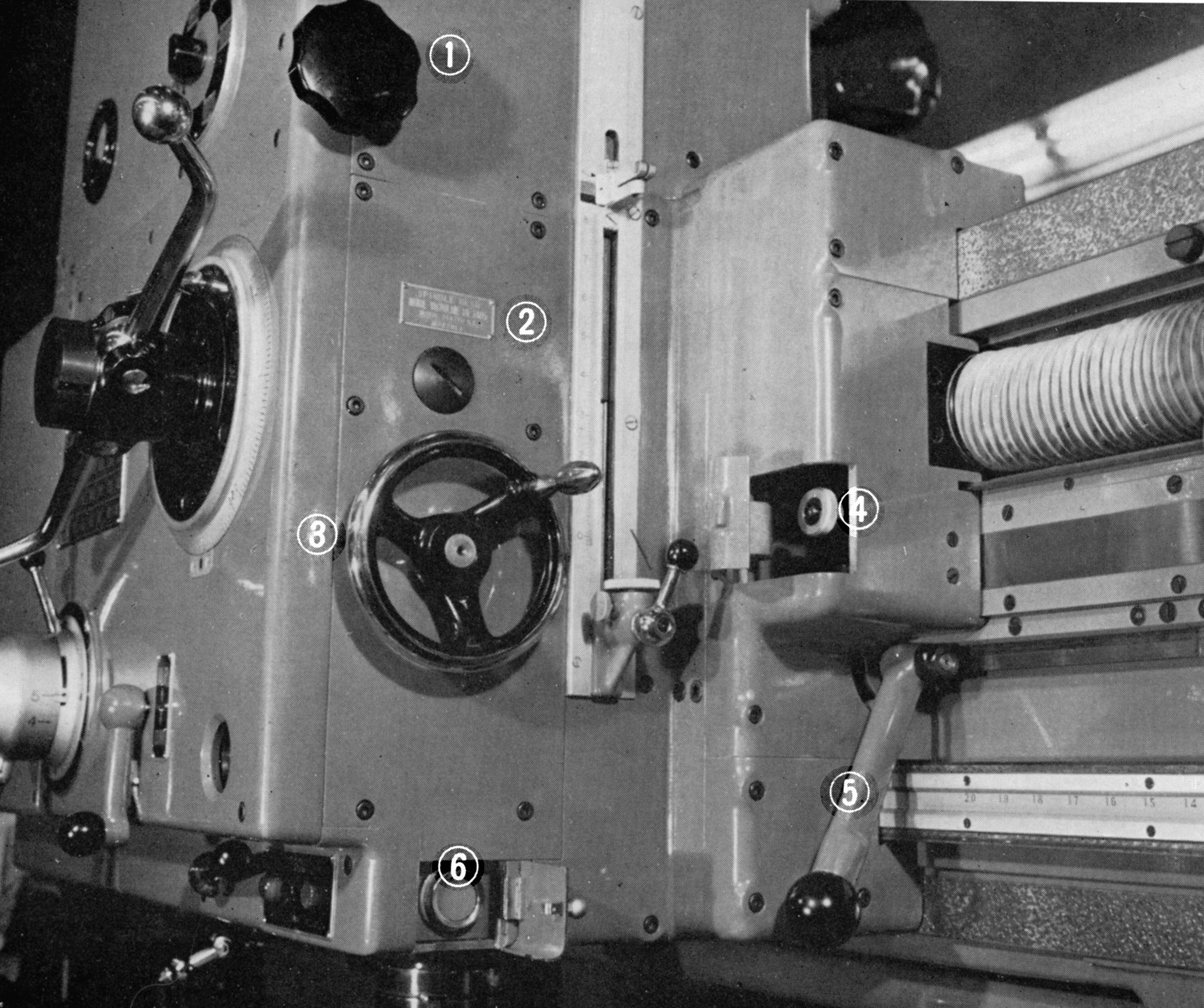
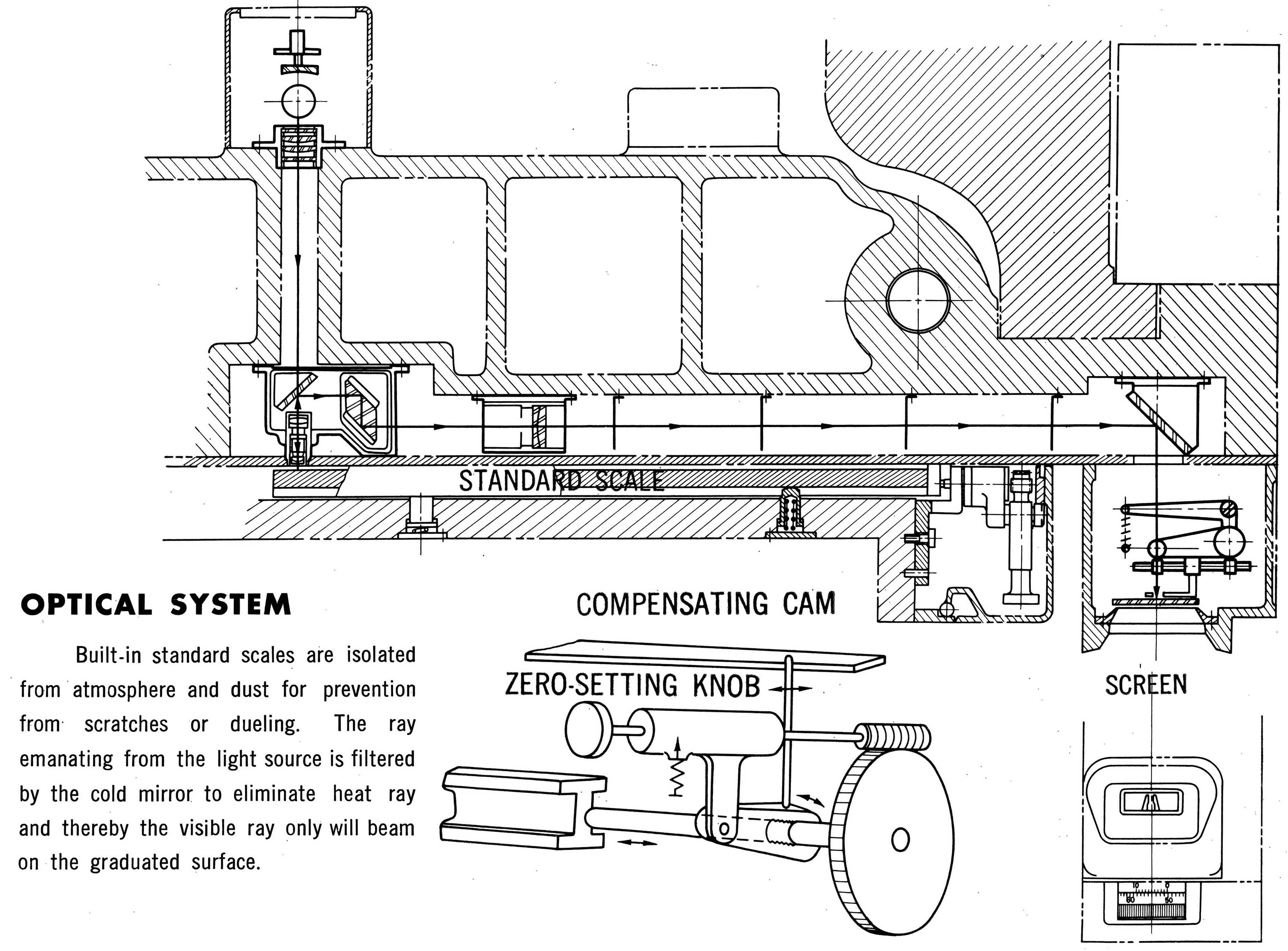
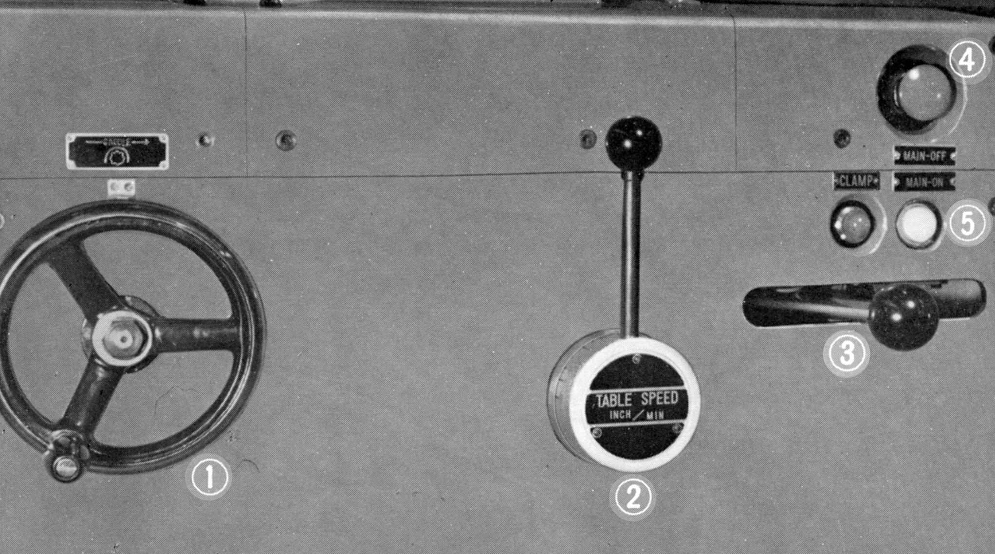
Workhorse of the Mitsui range was the No.5, a hydraulically-driven, double-column "planer type" jig borer with the table sliding longitudinally on a massive base casting. The head, held on a saddle, was able to be traversed from side to side on a beam that connected the two columns and raised and lowered through a range of 23.5 inches - all movements being by both hand and under power. These scales were claimed to be of exceptional accuracy and ruled on the Mitsui's own very highest precision dividing machines. They were inspected with reference to the most precise of the line standards of the N.P.L. (National Physical Laboratory of Great Britain) and designed to have as close an expansion coefficient to that of the machine body as possible. Optical readers were fitted to the right-hand side of the bed and on the cross beam, each being provided with a projection screen that magnified the divisions on what was called the "
standard scale" by a factor of 25. On the screen was a forked slit, the position of which, for vernier readings, could be adjusted by a "micro drum". In use, the operator would first set the table or spindle head to an accuracy of 0.05 inches using the ruler scales, this positioning a division line of the standard scale on the viewing screen. The line was then further adjusted, using the micro drum, to the third, fourth and fifth decimal divisions of the required setting. The table, or spindle head, was then moved using the appropriate fine-setting knob until the standard scale division line was aligned between the fork slit - the vernier setting of the latter reading to 0.00005 of an inch. In use, operators of optical systems say that they were surprisingly quick and easy to operate and, once used to the inevitable "black art" compromises needed, highly accurate. Optical readers were fitted to the right-hand side of the bed and on the cross-beam, each being provided with a projection screen that magnified the divisions on what was called the "standard scale" by a factor of 25. On the screen was a forked slit, the position of which, for vernier readings, could be adjusted by a micro drum. In use, the operator would first set the table or spindle head to an accuracy of 0.05 inches using the ruler scales, this positioning a division line of the standard scale on the viewing screen. The line was then further adjusted, using the micro drum, to the third, fourth and fifth decimal divisions of the required setting. The table, or spindle head, was then moved using the appropriate fine-setting knob until the standard scale division line was aligned between the fork slit - the vernier setting of the latter reading to 0.00005 of an inch. In use, operators of optical systems say that they were surprisingly quick and easy to operate and, once used to the inevitable "black art" compromises needed, highly accurate.
Carried on a very heavy and rigid box-type base, movements of the 5A's head in any direction were claimed to have only a slight effect upon the centre of gravity. In addition (as was normal with this type of jog borer) the table could not be moved to overhang the ends of its ways - both features adding to the theoretical rigidity and consequent accuracy.
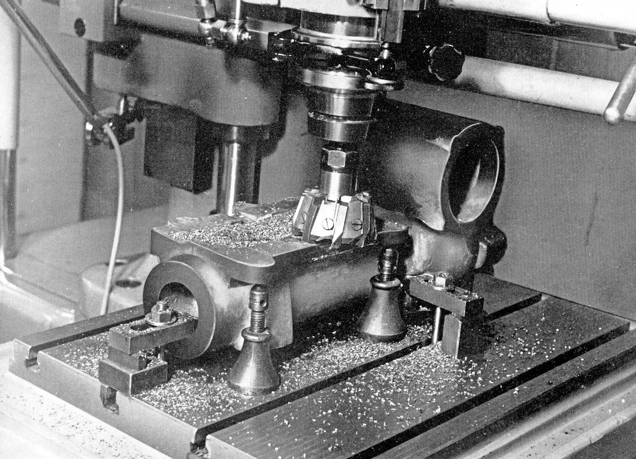
Driven by a 2-speed, 3 h.p./4 h.p. motor, the 8-inch-travel spindle had eighteen speeds that spanned 40 to 2000 r.p.m., the power down-feed rates being 0.0008, 0.0014, 0.0024, 0.005, 0.007 and 0.012 inches per spindle revolution. To allow tapping to be carried out - at speeds below 120 r.p.m. only -  the spindle direction could be instantly reversed, an automatic stop being fitted that worked at rates of feed and speeds. The stated drilling capacity was 2.375" and boring 10", both through cast iron. Fine and quick-action hand control of the spindle was also provided as standard by, respectively, a handwheel and lever. Handily, automatic tool clamping and unclamping from a No.4 Morse taper socket was also fitted, electrical push-buttons controlling a motor that moved the spindle drawbar.
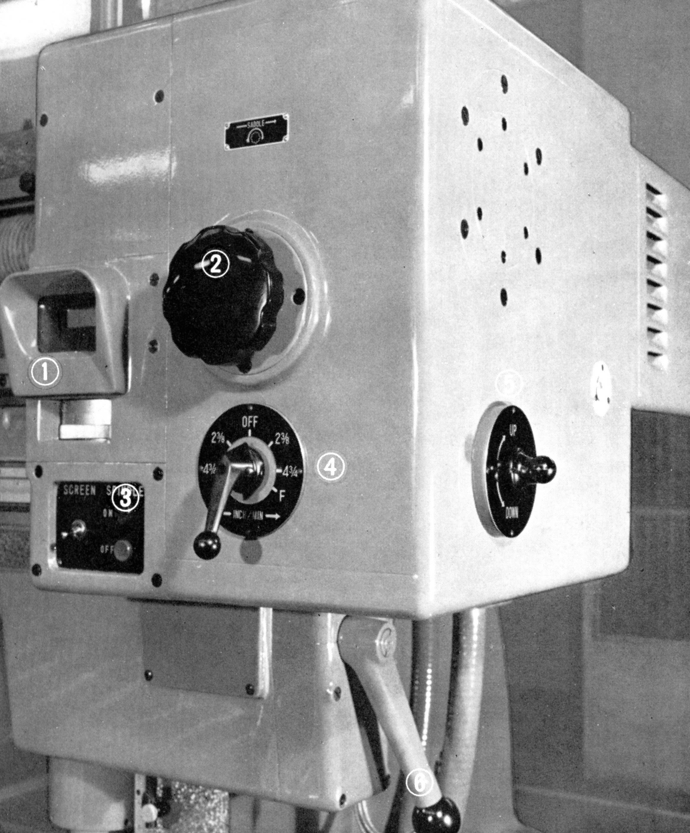
Carrying the spindle head on the cross-beam was a saddle, this having 20 inches of travel with the drive coming from a 2-speed, 2.3 h.p./2.5 h.p. motor working through a ball-screw and reduction gearbox. Two rates of feed were available when used for milling at 2 and 4 inches per minute, together with a rapid setting of 47.25 inches per minute.
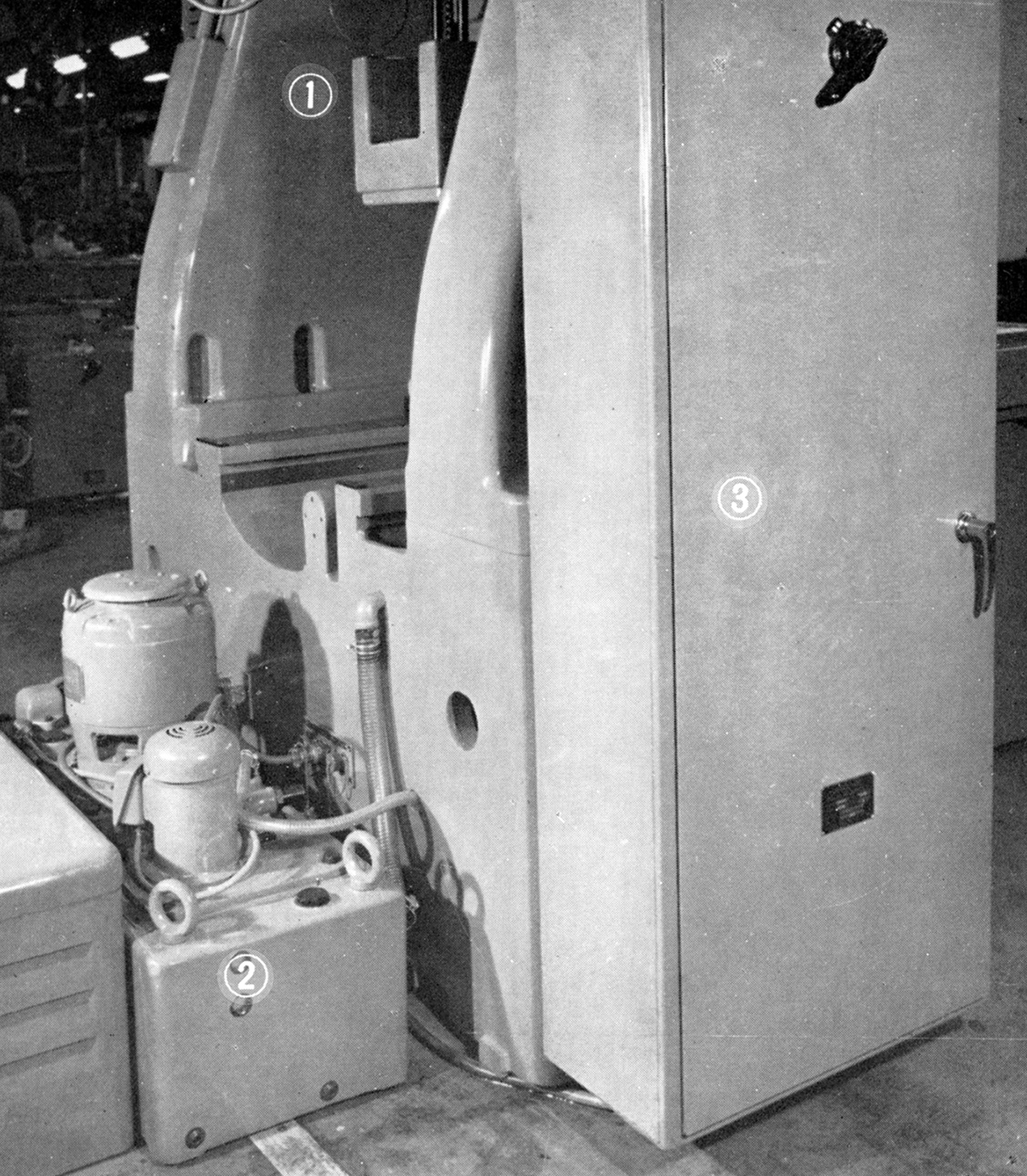
Driven hydraulically - for smoothness on changes of speed - and with a single lever to start, stop and reverse it, the table had a working surface of 33.5" x 26", a longitudinal travel of 29.5 inches and a range of infinitely variable, stepless feeds from 0 to 80 inches per minute. A separate, floor-mound hydraulic accumulator and storage tank was supplied, the pump being manufactured by Mitsui and arranged to automatically change its output according to differences between the cutting and positioning feeds. This arrangement was aimed at minimising heat-build up and ensure that as little as possible was transferred to the body of the machine. Also located separately and provided with the usual settling and baffling arrangements, the coolant tank was fitted with a pump driven by a 1/20 h.p. motor.
A wide range of accessories was listed by the maker, including a very complete, boxed, locating microscope set that included a drill chuck, centre point, proving bar, a locating attachment with dial indicator, an axial indicator, reference square, a screen illuminating device and a reduction sleeve from 4 Morse to 1 Morse with a clamping tool. Also available were sets of boring bars, twist drills, end-mill reamers, face-milling cutters, shell-end cutters, universal boring and facing heads, sets of collets and circular dividing and tilting rotary tables.
A Mitsui 5A jig borer required a floor space of 106" x 78" stood 110" high and weighed around 13,200 lbs (5987 kg)..


The first medium-sized jig borer by Mitsui, the No. 4 of 1935

For comparison, the SIP MP-5B of the early 1930; the MP-4B was a smaller model

Mirsui 5A jig borer as sold during the 1960s.

Sharing a number of features, the rather similar a Swiss-made SIP 6A from the 1960


Mitsui No.5A jig borer. A more modern machine from the 1960s and 1970s. Even its Model number badge is set at the same angle as on the Swiss models


Control Annotations 5A
1) rate of spindle power down-feed
2) depth measuring device
3) wheel for fine down-feed of spindle by hand
4) zero setting knob for the standard optical scales
5) lever for clamping the saddle that carries the spindle head to the cross beam
6) electrical push buttons to control spindle reverse rotation when tapping

Control Annotations 5A
1) lever for quill rapid feed by hand
2) spindle speed selector lever
3) lever to engage up and down spindle power feed
4) push buttons for auto tool clamping and release
5) quill clamping lever 

Control Annotations 5A
1) optical micro-drum read-out screen for the spindle head travel
2) knob to control the slow feed of the saddle carrying the spindle head
3) electrical push buttons for spindle start and stop
4) lever to select feed rates of the saddle carrying the spindle head in both direction (with rapid or milling feeds)
5) lever to control the vertical travel of the cross rail
6) lever to clamp the cross rail to the pair of vertical columns


Control Annotations 5A
1) balancing weight
2) hydraulic pump unit
3) electrical control cabinet

Control Annotations 5A
1) handwheel for slow feed of the table
2) lever for hydraulic feed of the table in both directions (rapid or milling feeds)
3) table clamping lever
4) emergency stop button
5) main electrical switch button

Dimensions of the Mirsui No.5A jig borer


Final assembly, checking machining test pieces before removal to the dispatch department

Ready for dispatch - s posed pictures suggesting the machines are being used


Catalogue Sets are available for Mitsui Jig Borers & other Machine Tools

Mitsui No.0, No.1C Jig Borer & Jig Borer Accessories  Mitsui No. 3A Jig Borer
   
Mitsui Jig Borer 4B  Mitsui Jig Borer 6A  Mitsui Jig Borer 7B 

Mitsui Jig Borers 4DN, 6CN, 7CN

Mitsui Seiki Full Production Range 1980s

Mitsui Jig Borers 3E, 4BMD, 4DN, 6CM, 6CN, 6BD, 7CM, 7BD and 7CN
Mitsui Seiki Jig Borers,Jidic 7N, No.0, No.3, No.5 and No.6
Precision Measuring Instruments MLA-250, MLB-2000, UMC-1000 and UMD-1000
Grinding Machines MUG27. MUG 50/27 and MUG 75
Leadscrew Measuring Machine, Electronic Indicator and Rotary Tables

Mitsui Seiki Jig Borers Japan
Home Page & No.5A

email: tony@lathes.co.uk
Home   Machine Tool Archive   Machine-tools Sale & Wanted
Machine Tool Manuals   Catalogues   Belts   Books  Accessories