 |
|
|
|
|
|
|
|
|
|
|
|
|
|
|
|
|
|
|
|
|
|
|
|
|
|
|
|
|
|
|
|
|
|
|
|
|
|
|
|
|
|
|
|
|
|
|
|
|
|
|
|
|
|
|
|
|
|
|
|
|
|
|
|
|
|
|
|
|
|
|
|
|
|
|
|
|
|
email: tony@lathes.co.uk
Home Machine Tool Archive Machine-tools Sale & Wanted
Machine Tool Manuals Catalogues Belts Books Accessories
Henry Milnes Planers
Milnes Lathes Home Page A Baby Planer for the Home Workshop
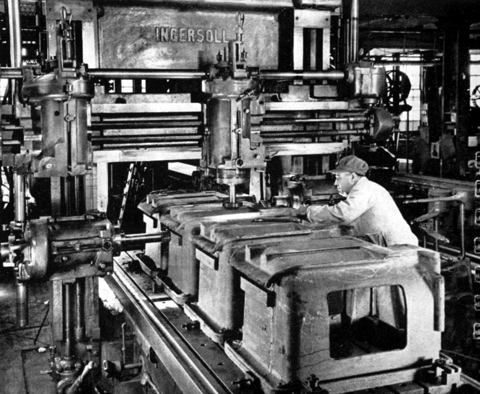
At one time the planer was considered an indispensable part of any machine shop, large or small - often being used to machine several identical jobs "ganged up" on the table - machine tool beds and other larger castings being typical examples, as shown here in the American Hendey factory. Today, planers they are still in use machining huge castings for a variety of industries for, using inexpensive tooling they can machine large components with relative ease and considerable accuracy. Some examples are huge, with beds fifty or sixty feet long and able to accommodate work sixteen feet high, and fitted with either fixed or pivoting grinding or milling heads in place of the ordinary "clapper-box" tool holder - this type being known as "planer-millers" or "planer-grinders" or, in some regions as the "plano-miller" and "plano-grinder". On larger types it's common to find more than one toolbox fitted, the cross-rail can often carry two or more, side by side, with several others sometimes mounted at the bottom and sides of the cross-rail support columns.
Some planers are made open-sided, and able to accommodate even larger jobs and, as so many specialised machining operations can be undertaken, it is often difficult to differentiate between planers and true millers - examples made by the huge American Niles-Bement-Pond Company have included: Multiple Spindle Horizontal Milling Machines, Horizontal Slab Milling Machines, Horizontal Slab Milling Machine, Rod Milling and Fluting Machine, Duplex Milling Machines, Forge Milling Machines, Plate Planers, Rotary Planers and End Milling Machines. Although the name changed according to the specific use, the principle of operation remained essentially the same, a long table sliding beneath (or between) single or multiple static or powered cuttings heads.
Other variations on the theme include "Pit" and "Breast" planers where the workpiece rests in a pit (or on a table) and the columns carrying the cross-rail and toolheads travel over it. These massive machines are generally reserved for the heavier kinds of armour-plate work intended for nuclear power stations and warships.
Planers have been made in almost every size increment imaginable, the smallest being tiny, hand-operated units designed for bench mounting and, although rare (and now highly sought-after), those suitable for an amateur's workshop do occasionally turn up. Not only do they have an engineering novelty and historical value, but because they are still capable of their original task - the economical machining of large components in a limited space - are still a most useful machine to have in the workshop of the serious amateur. In addition, as they work, they have a strange and rather beautiful hypnotic motion.
Milnes planers were not made in great numbers - the company's speciality was high-class lathes - nor in a wide variety of sizes, with just three models identified: one from around 1890 with no known model designation, just the maker's description of a 24-inch stroke (it's likely to have been offered in different sizes as well); the No.1 hand-operated model (that appears to have been unchanged from its introduction in 1910 to the end of production) and the No.2, this being fitted at first with a relatively simple drive system but then one of greater complexity that made the machine entirely self-contained with automatic reversal of the table and indexing of the cutting tool.
Further down the page can be seen pictures of a beautifully restored and working No.2 Milnes from the 1920s.
Continued below:
|
|
|
|
|
|
|
|
|
|
|
|
|
 |
|
|
|
|
|
|
|
|
|
The two Milnes planers offered in 1910: the No.1 hand-operated machine and the early power-driven No.2
|
|
|
|
|
|
|
|
|
|
 |
|
|
|
|
|
|
|
|
|
The No.1 hand planer as it appeared in the Milne's catalogue for 1922
|
|
|
|
|
|
|
|
|
|
 |
|
|
|
|
|
|
|
|
|
By 1922 the Milnes No.2 planer had become a more sophisticated machine with an ingenious, self-contained gearbox-beneath-the-bed drive system
|
|
|
|
|
|
|
|
|
|
|
The first automatic table drive reversing system that Milnes used (though not unique) was ingeniously arranged; a countershaft unit with a 3-section "fast-and-loose" pulley set was driven by a single belt that passed between two striker "hooks"; the hooks were controlled by a mechanism linked into the machine's motion in such a way that they could throw the belt from one outside pulley to the other. If the belt-shifting mechanism was disengaged, the belt came to rest on the centre "loose" pulley which, being free to spin on the shaft, stopped the feed.
Reference to a photograph towards the bottom of the page shows one of the forms of table reverse fitted to Milnes planers: a single shaft emerged from the drive pulleys and carried, at each end, a pinion gear - each of which engaged with its own crown wheel, the two wheels being mounted on concentric shafts.
With the belt positioned in the middle, or idle, position, the drive was started by lifting a lever that engaged the belt-shifting mechanism. The belt was moved first to the right-hand pulley which drove the outer of the two pinion gears; this advanced the table (by means of a rack fitted to its underside) under the toolbox and metal was cut. As the table came to the end of its travel a trip bar caused the belt shifter to fling the belt across to the left-hand pulley, and so engage the drive to the inner of the two pinions. Being "higher-geared", this returned the table at a higher speed to its starting point with the tool-carrying clapper box being knocked back on its hinge as the workpiece passed beneath it; from the returned position the cycle began, automatically, again.
Later Milnes planers (as shown below) had a very much more compact drive system that, while it retained a fast-and-loose pulley arrangement, employed a conventional gearbox mounted beneath the bed. On all models from the basic hand-operated type to the larger power-driven versions, the cutter head was also power fed across the job by the use of a simple ratchet feed, this being operated by a long rod that reached down and engaged with the table drive mechanism..
|
|
|
|
|
|
|
 |
|
|
|
|
|
|
|
|
|
A Milnes No.2 Planer from the 1920s in as-found condition
|
|
|
|
|
|
|
|
|
 |
|
|
|
|
|
|
|
|
|
 |
|
|
|
|
|
|
|
|
|
Trial assembly of the input drive pulley system with its fast-and-loose pulley drive and belt striker bars
|
|
|
|
|
|
|
|
|
 |
|
|
|
|
|
|
|
|
Trial assembly of the control system
|
|
|
|
|
|
|
|
|
|
|
|
|
|
 |
|
|
|
|
|
|
Later-type Milnes planer table drive gearbox
|
|
|
|
|
|
|
 |
|
|
|
|
 |
|
|
|
|
 |
|
|
|
|
|
|
|
|
|
|
 |
|
|
|
|
|
|
|
|
|
The two cast-iron uprights that carried the tool-holding bridge
|
|
|
|
|
|
|
|
|
 |
|
|
|
|
|
|
Underside of the table with, centrally disposed, two deep strengthening ribs
|
|
|
|
|
|
|
 |
|
|
|
|
|
|
|
|
|
|
 |
|
|
|
|
|
|
Underside of the table with, centrally, the slot into which the drive rack fitted
|
|
|
|
|
|
|
 |
|
|
|
|
 |
|
|
|
|
|
|
|
|
|
Boss the slide along the cross beam with its circular T-slot
to hold the swivelling tool slide and engraved degree divisions
|
|
|
|
|
|
|
|
|
 |
|
|
|
|
|
|
|
|
|
 |
|
|
|
|
 |
|
|
|
|
|
|
|
|
Early design of Milner planer table drive and table reversing mechanism
|
|
|
|
|
|
|
|
|
 |
|
|
|
|
 |
|
|
|
|
 |
|
|
|
|
|
|
The pivoting toolpost had two T-slots and a rather elegant toolholder with bevelled sides. The bar and rods to the side provided automatic indexing to the cross-head feed.
|
|
|
|
|
|
|
|
|
|
|
|
|
|