 |
|
|
|
|
|
|
|
|
|
|
|
|
|
|
|
|
|
|
|
|
|
|
|
|
|
|
|
|
|
|
|
|
|
|
|
|
|
|
|
|
|
|
|
|
|
|
|
|
|
|
|
|
|
|
|
|
|
|
|
|
|
|
|
|
|
|
|
|
|
|
|
|
|
|
|
|
|
|
|
E-MAIL Tony@lathes.co.uk
Home Machine Tool Archive Machine-tools for Sale & Wanted
Machine Tool Manuals Machine Tool Catalogues Belts
Books Accessories
MAS, Zbrojovka & TOS
18S-VR Toolroom Lathe
An Instruction Manual and Sectional-drawings
Parts Manual is available for this lathe
MAS Home Page
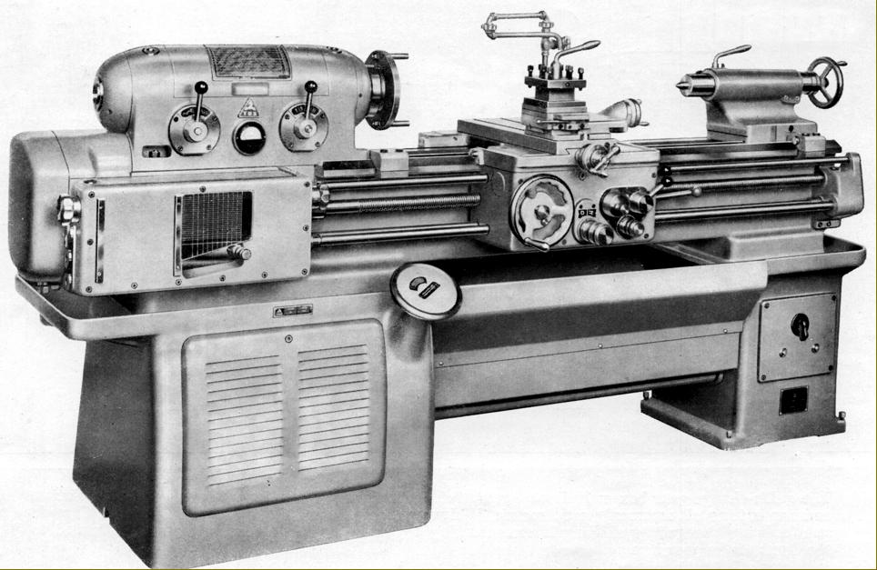
Originally developed and manufactured at the TOS works in Kurim the 7.5-inch (380 mm) centre height by 30", 40" or 50" (750, 1000 &1250 mm) between-centres "MAS" 18SVR Toolroom lathe was later made in the town of Trencin, in western Slovakia (formerly Czechoslovakia) and marketed in the United Kingdom was sold in the UK (initially through Elgar machine tools of Feltham, Middlesex and then by the 600 Group through their Selson Company) using three different brand names: Zbrojovka, TOS and MAS. At a time when the Eastern Block countries and the USSR were desperate for Western currency the lathe was offered at a very competitive price and enjoyed considerable success. The design (using unaltered main components) was continued into the 1980s as the Models SV-18RA, SV-18RB and SV-18RD, though with the styling given a more modern, angular look and a number of improvements made to the drive and lubrication systems.
Although the V-way bed was deep, massively constructed (without a gap to weaken it) heavily cross-ribbed and supplied hardened as standard it was "only" 13.5 inches wide and so just short of the 15 inches that would have made the traditionalists happy who insist that, to qualify it as a "toolroom" lathe, the width must be equal to, or greater than, twice the centre height. Because the bed ways ran past the front and back of the headstock the carriage was able to have its cross slide to be mounted properly on the centre line - yet the cutting tool could still be run right up to the spindle nose without having to advance the tool slide beyond it normal position. The bed was carried on two very rugged cast-iron plinths joined by a deep, slide-out chip tray; unfortunately there was no storage in the stand, not even a simple tool tray.
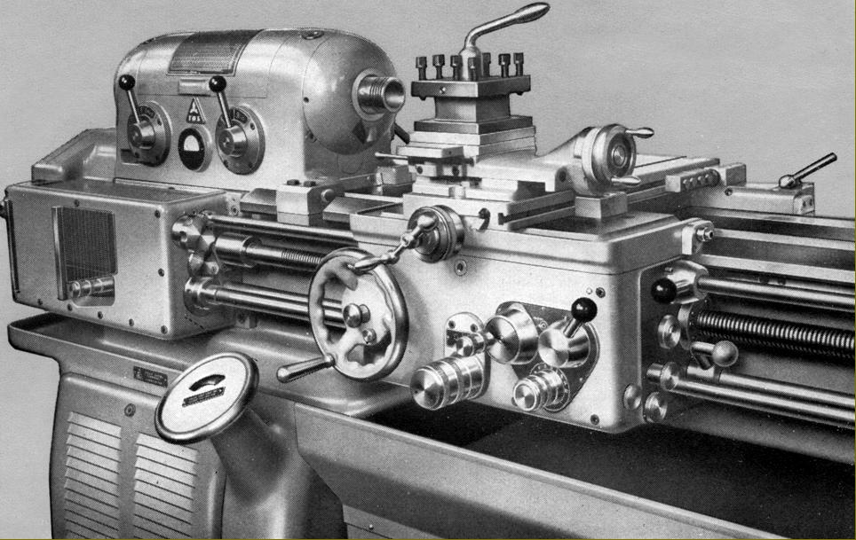
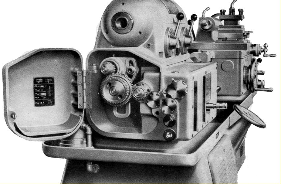
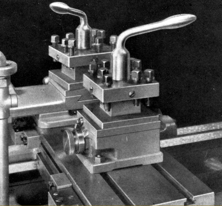
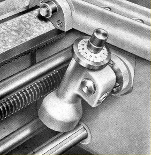
Both cross and top slide were fitted with proper taper-gib strips (with front adjuster and back stop screws) and, unusually, for a lathe of this type and size, the cross slide carried two T slots that ran front to back in the manner once common on smaller Austrian-built Emco screwcutting lathes. Fitted with such T slots the cross slide could be much more easily and quickly adapted to carry a range of accessories including a rear toolpost, travelling steady, ball-turning attachment or a powered, high-speed milling or grinding head. The compound-slide zeroing micrometer dials were not as large as they should have been yet, surprisingly, the makers went to the trouble of arranging the top slide feed-screw with an intermediate 'step-up' gear that allowed the dial to be set above the slide's top surface and so made larger and easier to read. To assist with screwcutting the cross slide was fitted with a quick-withdrawal mechanism whereby the tool could instantly pulled back but then returned to the exactly same position, ready to apply a little more cut, when the carriage had been wound back to the start point.
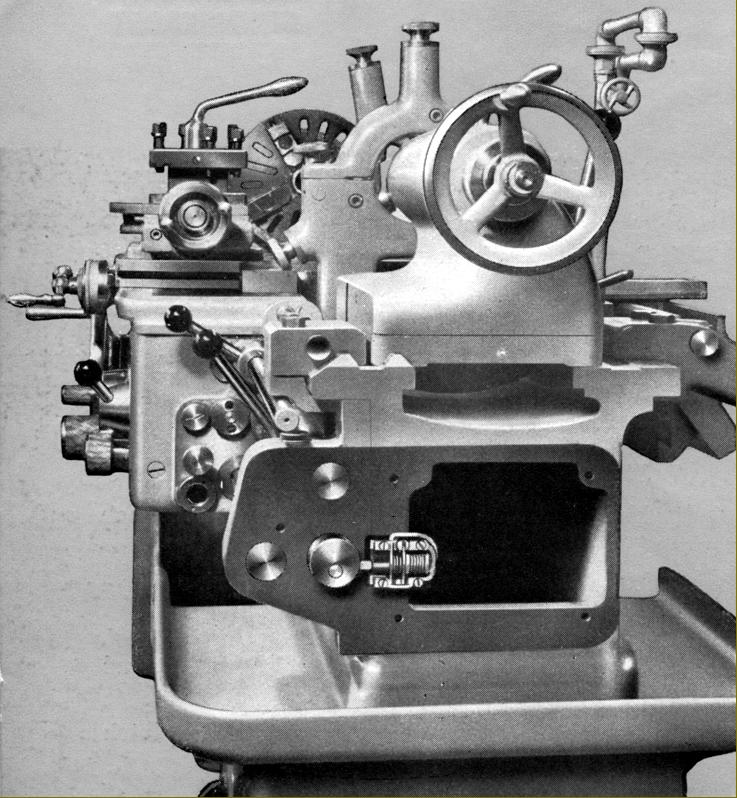
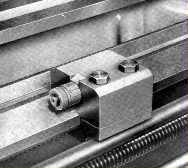
Sliding and surfacing feeds were provided by a separate power-shaft parallel and below the ground-finish leadscrew (which was use only for screwcutting). The apron was robustly built and fitted with a centralised lubrication system operated by a hand pump - the flow from which could be checked through a small window - that oiled all the gears and shafts through distribution pipes and galleries. Unfortunately, in contrast to many other lathes with a similar system, the oiling was not continued up to the bedways or cross slide. The power-feed mechanism was fitted with an automatic disengage mechanism that worked not just on both left and right longitudinal movements but also, and with great convenience to the operator, on the cross as well. The mechanism did not just disengage the drive, it passed it through a spring-loaded safety clutch the release tension of which could be set by partially pulling out and turning an adjustment handle. The standard stops used to knock off the feeds could be replaced, at extra cost, by micrometer-adjustment versions with a longitudinal scale engraved in inches and "circumferential lengths" in steps of 0.05 mm.
Electrical stop, start and reverse of the spindle was by a third-rod system, the operating lever being pivoted from the right-hand face of the apron . The makers recommended that this system could also be used as a brake (but only for lighter work) by moving the control into reverse momentarily before returning it to the neutral position; for heavier jobs "the operator .. must wait for the machine to stop." Unfortunately the main electrical switchgear was mounted well out of reach on the font face of the tailstock-end cabinet plinth - presumably the makers were oblivious to the very real dangers of putting such vital controls out of the operator's reach.
Continued below:
|
|
|
|
|
|
|
|
|
|
|
|
|
 |
|
|
|
|
|
|
7.5-inch (380 mm) centre height by 30", 40" or 50" (750, 1000 &1250 mm)
between-centres "MAS" 18SVR Toolroom lathe.
|
|
|
|
|
|
|
|
|
Continued:
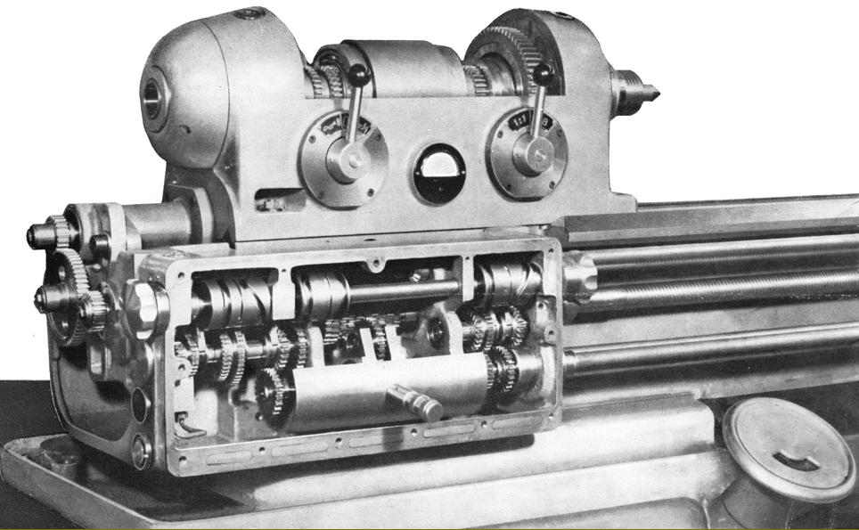
Distinctively barrel-shaped, the headstock of the SV18R contained a 15/8" (41 mm) bore spindle running in adjustable, parallel-bore high-precision plain bearings; these were tapered on their outer surface and compressed into their (tapered) housings by rings screwed onto the headstock nose and tail. The bearings, together with the ball-bearing supported, 8 : 1-ratio backgear assembly fitted under the front section of the spindle, were lubricated by filtered oil lifted by a powerful electric motor from a 7-litre tank in the headstock-end pedestal. Because the pump started work as soon as the lathe motor was switched on it was possible for the operator to ensure that oil was flowing (through two inspection windows on top of the headstock, directly above the bearings) before committing the machine to work. The spindle carried a single, very wide flat pulley that ran in its own ball races (to isolate effects of belt pull and reduce vibration) with the drive transmitted through a long key; the drive came from a piston-pump-lubricated gearbox fitted into the base of the stand that was controlled by a large, smooth-edged handwheel below and in line with the spindle nose - a wheel that looked remarkably like the one fitted to the English CVA toolroom lathe, even to the window cut in its face to reveal the r.p.m. setting engraved on a disc beneath. Instead of the 5 h.p. motor one would have expected on a machine of this class, an 8 hp one was fitted; bolted to the top of the gearbox it drove through 5 V-belts and provided such a surfeit of energy that deep cuts on top speed could be taken with impunity. With such power available the makers wisely decided to fit a large Ampere-meter, in the front face of the headstock; to advise the operator against the danger of overloading at slow spindle speeds; it was marked in red to show 14, 22, 35 and 56 rpm with contrasting black numbers advising the maximum horse power that could be used at each setting.
Driven from a screwcutting gearbox of conventional design, with a "Norton-type" sliding tumble selector on the front (and neat rotary controls on the left and right-hand faces) and using a 4 t.p.i leadscrew, the lathe (at least on those models exported to the UK) was able to generate a range of English pitches from 0.2 to 140 t.p.i - as well as metric from 0.2m to 14 mm pitch, Module 0.25 to 70 and Diametral 1 to 224 t.p.i - the latter only by altering the set of changewheel on the drive bracket. Longitudinal power feeds varied from 0.0008" to 0.21875" and cross feeds at exactly half those figures - all per revolution of the spindle. In line with the expected heavy-duty use the gearbox was lubricated positively by the action of a piston pump that distributed its output through pipes to all part of the assembly.
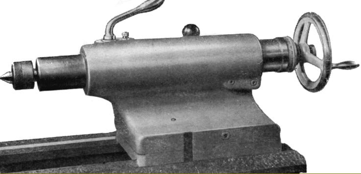
Able to be set over in the usual way for taper turning, the tailstock held a No. 3 Morse taper spindle fitted (to accurately measure its rather short 4.75-inches of travel) with both an adjustable micrometer collar on the handwheel and a ruler scale engraved into its hardened and ground surface.
The lathe was approximately 950 mm deep for all versions and 2520 mm, 2720 mm and 3020 mm long and 1730 kg, 1800 kg and 1850 kg in weight for the 750 mm, 1000 mm and 1250 mm between-centres capacities respectively.
Once an entirely centralised, state-controlled industry (largely devoted to supplying the Soviet Union and its satellite Eastern Bloc countries) the Czech machine-tool industry is now (from the late years of the 20th century) privatised and broken into many smaller units with 80% of production exported to countries within the EU, America and Canada. Although the well-known "TOS" brand is thought of by many Western engineers as one company in its homeland the description translates loosely as: "machine-tool builder," and the initials were once applied (under state control) to many diverse industries; with privatisation legal negotiations allowed only some firms to keep the valuable "trademark" but even those who failed often adopted a variation on the theme to get around the restrictions - Toshulin, for example using "TOS Hulin" as a workaround.
Today (2004) "ZPS Zlin" is the largest Czech machine-tool builder with "ZPS" the parent company and "Zlin" the city in which they are located. By concentrating on a low-cost and popular range of vertical machining centres ZPS Zlin manufactures more machine tools every year than the total output of all other Czech makers combined. Other Czech machine-tool companies include:
Cetos Hostivar Cylindrical grinding machines
CKD Blansko CNC-controlled Vertical Boring Machines
Intos Zebbak Milling machines
Kovosvit Holoubkov Radial Drilling Machines
Metal Press Power Presses
Retos Vanrsdorf Horizontal Boring Machines
Skoda Heavy-duty Lathes and "floor borers"
Smeral Power Presses
Stanko Metal-cutting and Metal-forming Equipment
Strojimport Metal-cutting & Metal-Forming Equipment
Strojtos-Lipnik Milling Machines
Toma Trnava Power Presses
TOS (Celakovice) Lathes
TOS (Galanta) Lathes
TOS (Kurim) Milling Machines, Drilling Equipment, Machining Centres, Transfer Lines
Toshulin Vertical Lathes
VSS (Kosice and Zdas) Power presses
|
|
|
|
|
|
|
|
|
|
|
|
|
|
|
 |
|
|
|
|
 |
|
|
|
|
 |
|
|
|
|
|
|
|
|
|
|
 |
|
|
|
|
|
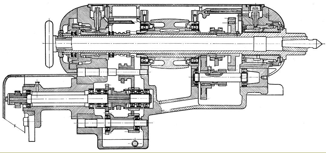
Section through headstock showing clearly the plain-bore, tapered outside spindle bearings and the drive pulley supported in its own ball races
|
|
|
|
|
|
|
|
|
|
|
|
 |
|
|
|
|
 |
|
|
|
|
|
|
Forward, reverse and neutral electrical switch was mounted inside the tailstock end of the bed
|
|
|
|
|
|
|
 |
|
|
|
|
|
|
|
|
|
 |
|
|
|
|
|
|
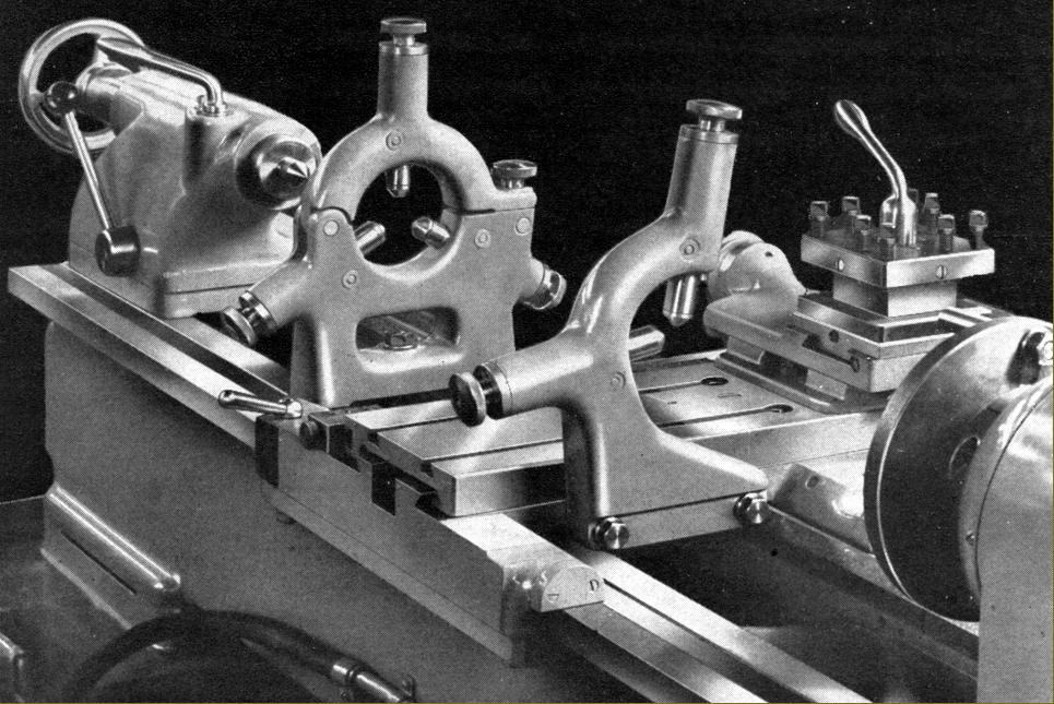
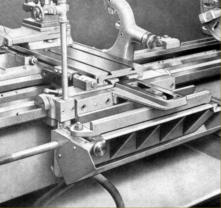
Fixed and travelling steadies
|
|
|
|
|
|
|
 |
|
|
|
|
Of conventional design, the set-over tailstock had a hardened, ground and lapped spindle with a 120 mm (4.75") stroke, a No. 3 Morse taper socket, metric ruler graduations and a large-diameter zeroing micrometer dial. A proper split-cylinder clamp locked the spindle and the whole assembly was secured to the bed by a lever-operated eccentric cross shaft (though it lacked a second bolt to help with heavy work).
|
|
|
|
|
|
|
 |
|
|
|
|
|
|
The top slide was fitted with a quick-withdrawal lever for use when screwcutting
|
|
|
|
|
|
|
|
|
|
|
|
 |
|
|
|
|
|
|
|
|
|
|
 |
|
|
|
|
|
|
|
|
|
|
 |
|
|
|
|
|
|
|
|
|
|
|
|
|
|
|
 |
|
|
|
|
|
|
|
|
|
|
 |
|
|
|
|
|
|
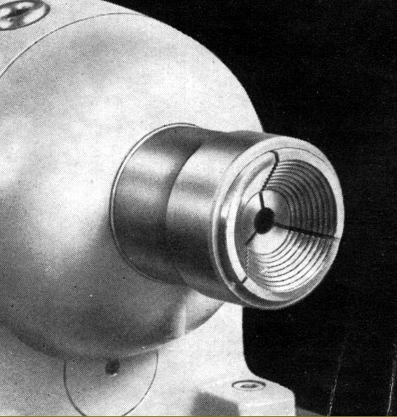
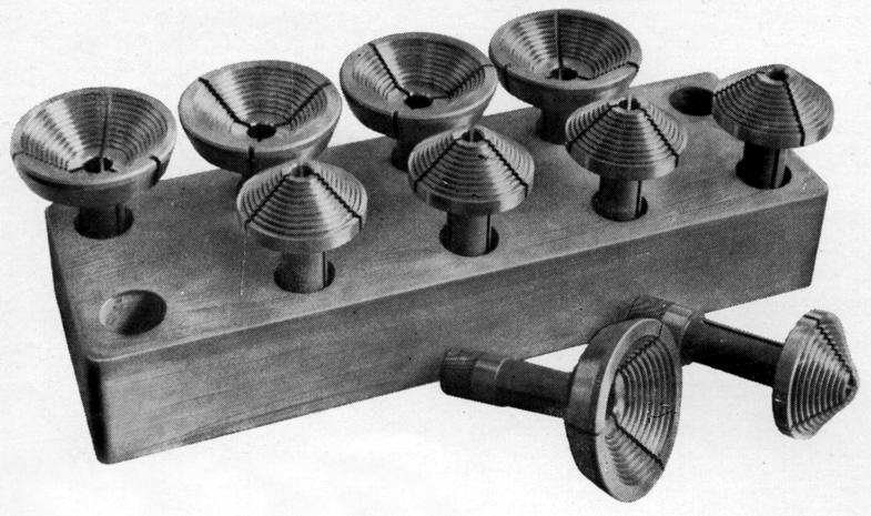
Spindle-nose adapter to take the cone collets
|
|
|
|
|
|
|
 |
|
|
|
|
|
|
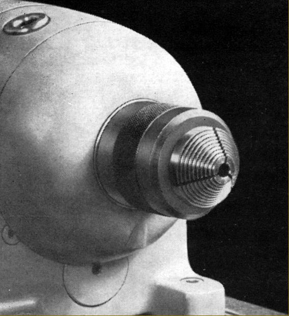
Spindle-nose adapter to take the fir-tree collets
|
|
|
|
|
|
|
|
|
|
|
|
 |
|
|
|
|
|
|
Cone and fir-tree collet set
|
|
|
|
|
|
|
 |
|
|
|
|
|
|
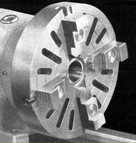
Typical faceplate-cum-4-jaw chuck as supplied by many continental makers until the late 1960s
|
|
|
|
|
|
|
 |
|
|
|
|
|
|
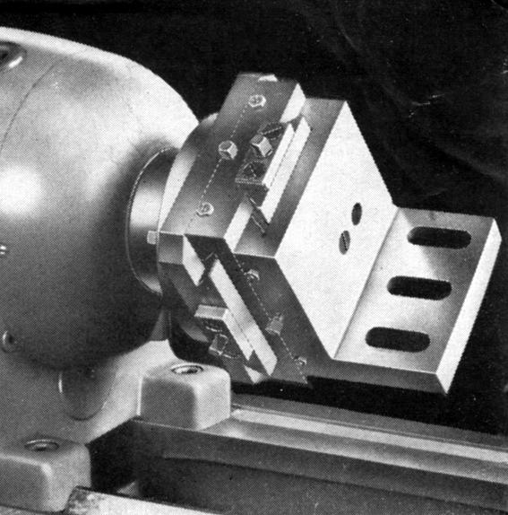
A most unusual spindle-nose fitting: an angle plate mounted on a compound slide rest
|
|
|
|
|
|
|
|
|
|
|
|
|
|
|