 |
|
|
|
|
|
|
|
|
|
|
|
|
|
|
|
|
|
|
|
|
|
|
|
|
|
|
|
|
|
|
|
|
|
|
|
|
|
|
|
|
|
|
|
|
|
|
|
|
|
|
|
|
|
|
|
|
|
|
|
|
|
|
|
|
|
|
|
|
|
|
|
|
|
|
|
|
|
|
|
|
|
|
|
|
|
|
|
|
|
|
|
|
|
|
|
|
|
|
|
|
|
|
|
|
|
|
|
|
|
|
|
|
|
|
|
|
|
|
|
|
|
|
|
|
|
|
|
|
|
|
|
|
|
|
|
|
Believed to have been based first at 11 Montauk Street, in Bridgeport, Connecticut (an address used until at least 1941, the Linley Brothers Company was later based at 682 State Street Extension in the same city. The Linley seems to have been made from the early 1930s, first as a very simple machine, probably just for bench mounting, and then - from the late 1930s - as the more familiar Mk. 1 in bench and floor-stand versions and then - from 1963 - as the Mk. 1A, this model also being distributed using Boyer-Schultz branding. The last models were produced during 1967, after which the firm went out of business. If the simple sequential-serial number system employed by the makers is taken at face value, some 4565 examples appear to have been manufactured. However, the machine was also copied in Britain; first as the "Excel No. 1" - Excel being a generic marketing name used by the large B. Elliott Machinery Group for their range of better-quality cloned machines - then by Downham Engineering through several improved versions that were sold as the "Elliott Mini Jig Borer".
Nothing like the Linley is made today - and anyone needing a very high quality, accurate and easy-to-use miniature jig-borer/precision vertical miller (the SIP No. 1H, No. 2P and various Hauser units for example) will have to seek one on the second-hand market. Fortunately, most examples of the type tend to have had easy lives in toolrooms and experimental departments and finding a really good one is not as difficult as it might seem.
Very similar in design to the Vernon, its American-made competitor, the Linley was constructed along traditional jig-borer lines with the table non-elevating and the main head arranged to move up and down a slideway formed on the inside front face of the main column. The aim was to produce a structure that was as rigid as possible and with a dead-level, well-supported mounting for the table. As the machine evolved towards the 1A - where the most significant change was to the width and rigidity of the compound table and its mounting - the table ways were enlarged, the cross travel increased slightly, the design of table lock and collet changed and the drive belt more completely enclosed. Of massive proportions for its capacity, the head was counterbalanced by a weight hanging from a chain inside the main body; although on early machines the head was repositioned through its 8 inches of travel by hand, on later examples a distinctive 4-spoke capstan handle was fitted on the right-hand face of the column to make the task easier. With great ingenuity the designers did not just allow the weight to balance the head but arranged for the chain to lift in the middle of a flat bar that connected to both the main casting and the quill - thus cleverly counterbalancing the latter whilst also reducing backlash.
A 0.5 HP motor was fastened to the back of the machine and drove forwards via a ball-bearing supported and adjustable intermediate pulley to the main head by V-belts. 8 speeds were provided on both Mk. 1 and Mk. 1A models of: 275, 430, 550, 860, 1250, 2125, 2500 and 4250 rpm; all the pulleys (the motor and intermediate in aluminium, the spindle in "semi-steel") were dynamically balanced. In later years, the option was offered of a rather large variable-speed drive unit from a 220v AC 3-phase motor running at a constant 1200 rpm. The unit was entirely self-contained (it simply replaced the standard motor) and used a traditional type of mechanical expanding and contracting pulley system. The plate fixed to the unit gave speeds running from 283 to 2840 rpm but, by the time the drive reached the spindle via a standard V belt - which could be positioned on one of two differently-sized pulleys - the full range became a most useful 110 to 3000 rpm. Speeds were varied in each range by turning a large handle on the right-hand side of the unit.
The very first machines had a simple cover in cast iron that guarded just the front pulley and left the other two, on motor and intermediate shaft, exposed; later versions had a front-hinged guard, stayed by a two-part tie bar, that neatly and safely covered all three. The quill travel was 3-inches and the distance from its centre to the column ways (the throat) 5.75-inches. The spindle assembly - beautifully made in nickel-chrome steel - was double heat-treated, ground all over, lapped on its bearing surfaces and contained in two pairs of ABEC-7 rating, specially-selected, high-precision bearings that were claimed to need no adjustment in service - and which were provided with fifty pounds of pre-load pressure. To obtain perfect concentricity, both the outer diameter of the quill and the spindle nose were finish-ground and, to prevent the spindle suffering interference from pull by the drive belt, its pulley (mirroring the arrangement used on many high-class lathes), was given its own independent set of ball races.
Continued below:
|
|
|
|
|
|
|
|
 |
|
|
|
|
|
|
|
|
|
|
|
|
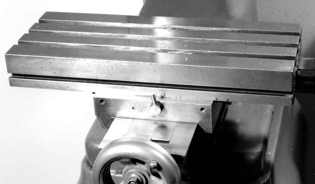
An early Linley Jig Borer with the later table with three T-slots in place of the original one slot. The narrow base of the saddle way, and the table lock acting directly on the gib strip, are both clearly evident on this early-model machine.
Continued:
Collets were held in the quill by a compression nut on the nose - and could be had in sizes from 1/8" to 1/2" in increments of 1/32". Early collets were of the ordinary split-from-one-end type, which limited the machine's usefulness as a light-duty vertical miller, the sideways forces on the cutters causing them to work loose unless only the most judicious of cuts was taken; in what must have been a recognition of the fact that so tempting a small machine would (unless locked in a strong-room) inevitably be pressing into service for other than boring accurate holes, Linley equipped the Mk. 1A with the vastly-superior Schaublin Type ESX collet; this type had slits running from both ends and was specially designed to provided a secure grip on the shanks of small cutters.
Linley had offered a down-travel-only power-feed head as an optional extra for some time, but with the coming of the 1A it was made standard - though, no doubt, they would not have refused to sell a machine without and not all 1As may be so equipped. The feed was taken from a belt-drive arrangement within the head, via a clutch, to an enclosed gearbox which provided a drive of 0.0015" per revolution of the spindle; an automatic-disengage mechanism was included. By 1964 the feed had been modified to produce a power movement in both directions and it was this style of gearbox that was used on the improved copies built by Downham in England. In order to ease the operator's workload on boring operations the head was fitted with a very useful Direct-reading Micrometer Depth Gauge with a graduated bar passing through a boss on the side of the casting. Its method of operation was simple: to machine to a depth of 1.167 inches the cutting tool was set in contact with the work and the bar moved until it was at any even line. The stop-screw was then lowered until it made contact with the top of the bar - and locked. The dial was set to zero, locked and then the bar lowered 11 divisions; the cut could now be made until the stop-screw was met. If the stop-screw was then released the remaining distance of 0.067" could be accurately measured by using the large and clear down-feed dial.
While very early tables had been just 5.5" x 14.5" long with a longitudinal travel of 9 inches, across of 5 inches and with a maximum clearance between spindle nose and table top of 9 inches, that on the late-model Mk. 1A was significantly improved - the hardened (heat-treated) table becoming 17.5 inches long and 7 inches wide with movements of 10 inches longitudinally and 6.5 inches across (some specification sheets claimed 6 inches on earlier machines). The maximum distance from the spindle nose to the table's top surface was 11.5 inches.
Because the main purpose of a jig borer is to space out and machine holes with great accuracy (typically for making a holding or drilling jigs to assist in a repetitive production processes) it is important that, once the cutter has been positioned, the act of locking the table to allow the cut to take place does not cause it to move out of alignment. To this end, at some point during the production of the early machines, and in order to improve rigidity, the table ways were made slightly wider and fitted with what the makers called a "flexible-blade, non-influencing type table lock" whose function was to "prevent longitudinal movement whilst absorbing any lateral pressure from the lock screws." In other words, they admitted that the original table lock that pressed against the gib strip did move the table slightly and had been replaced by one that avoided the problem.
Because the machine was in three sections - base cabinet, knee section and main column - it was possible to introduce a distance piece between the two upper parts and so increase the spindle to table distance by around 4 inches. The sides of the table slideways were square, not dovetailed and the three T slots were 1/2" wide on the Mk. 1 and 3/8" on the Mk. 1A; the gib-strip adjustment on the Mk. 1A was simplified by the use of self-locking inserts rather than the previously-used, fiddly-to-set lock nuts; all the 'working' flat and sliding surfaces of the machine were hand-scraped to a precision fit. For a small machine the 10 t.p.i Acme-form, heat-treated and ground table-feed screws were huge, a full 7/8" in diameter with the zeroing micrometer dials on all three axes scaled in proportion and consequently a massive 5" in diameter; the micrometer scale was engraved around the full diameter of the handwheel, provided with a 0.0001" vernier scale and plated in a beautiful non-glare, satin-chrome finish. Although early models had comparatively tiny 2.5" micrometer diameter dials it is possible, due to the long-lasting nature of these machines, that many were retro-fitted with the later, larger versions. The movement of the feedscrews was silky-smooth and the locking mechanism - which passed through the face of each dial - held the reading without disturbing the setting; the distance between the 100 graduations on each 5-inch dial was 0.157 inches and hence accurate vernier readings could be taken without recourse to a magnifying glass; as a further aid to accurate setting-out, each table movement was fitted with a finely-engraved ruler equipped with adjustable stops.
The most important change to the machine came with the redesign of the compound table assembly; the alterations were significant (although the size of the table remained unchanged) with the saddle supported on two additional ways at the very outside edges of the knee to produce a 100% increase in bearing area. The table-to-saddle contact was also modified to improve the bearing area by over 400% - an examination of the picture here will show just how broad and strong this new arrangement was. With the outer edges of the saddle reaching to the very nearly the full width of the machine, and the saddle being heavier than the table, the effect was to give much better support to jobs when the extremes of travel had to be used; the Linley Company's rather clumsy description of this feature was ".. providing ideal balance characteristics though less lateral change in centre of gravity."
In 1964 the basic machine cost $3285 which included a motor, starting switch, wrenches and a light unit. The collets were $14.75 each, the rotary table $198, a precision machine vice $150, the step block and clamp set $40.50 and a Criterion boring bar with a collet fitting shank $70.50. A variable-speed drive unit was an additional $219.
If the prices were extrapolated to the present time (2017) then a new Linley would cost in the region of $25,666; the fact that ones in good condition can be picked up for a fraction of this indicates that here is one machine that a keen amateur, or smaller professional workshop, could well afford to consider. The 1A Linley weighed about 800 lbs and required a floor space of 29.5" wide and 36 inches deep.
The writer would be delighted to hear from anyone with Linley sales literature - or able to provide photographs of any early model, especially that with a single T-slot table..
|
|
|
|
|
|
|
|
|
|
|
|
|
|
 |
|
|
|
|
|
|
A 0.5 HP motor was fastened to the back of the machine and drove forwards via a ball-bearing supported and adjustable jockey pulley to the main head by V belts. 8 speeds were provided on both Mk. 1 and Mk. 1A models of: 275, 430, 550, 860, 1250, 2125, 2500 and 4250 rpm. All the pulleys were in aluminium and were dynamically balanced. The very earliest models had a simple guard which covered just that part of the drive belt nearest to the operator, later versions had a complete cover which hinged forwards and was restrained by a simple hinged tie bar.
|
|
|
|
|
|
|
|
 |
|
|
|
|
|
 |
|
|
|
|
|
|
The most important change to the machine came with the redesign of the compound table assembly; the alterations were significant (although the size of the table's top remained unchanged) with the saddle supported on two additional ways at the very outside edges of the knee to produce a 100% increase in bearing area and the table-to-saddle contact also modified to give an increase in bearing area of over 400%;
|
|
|
|
|
|
|
|
|
|
|
|
|
|
|
|
|
 |
|
|
|
|
|
|
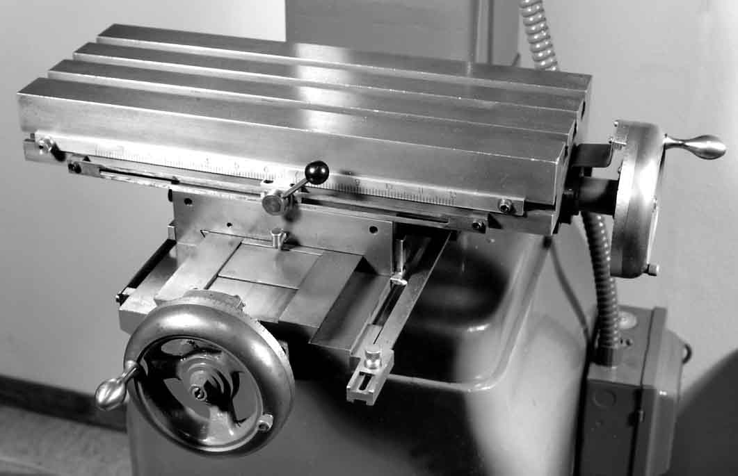
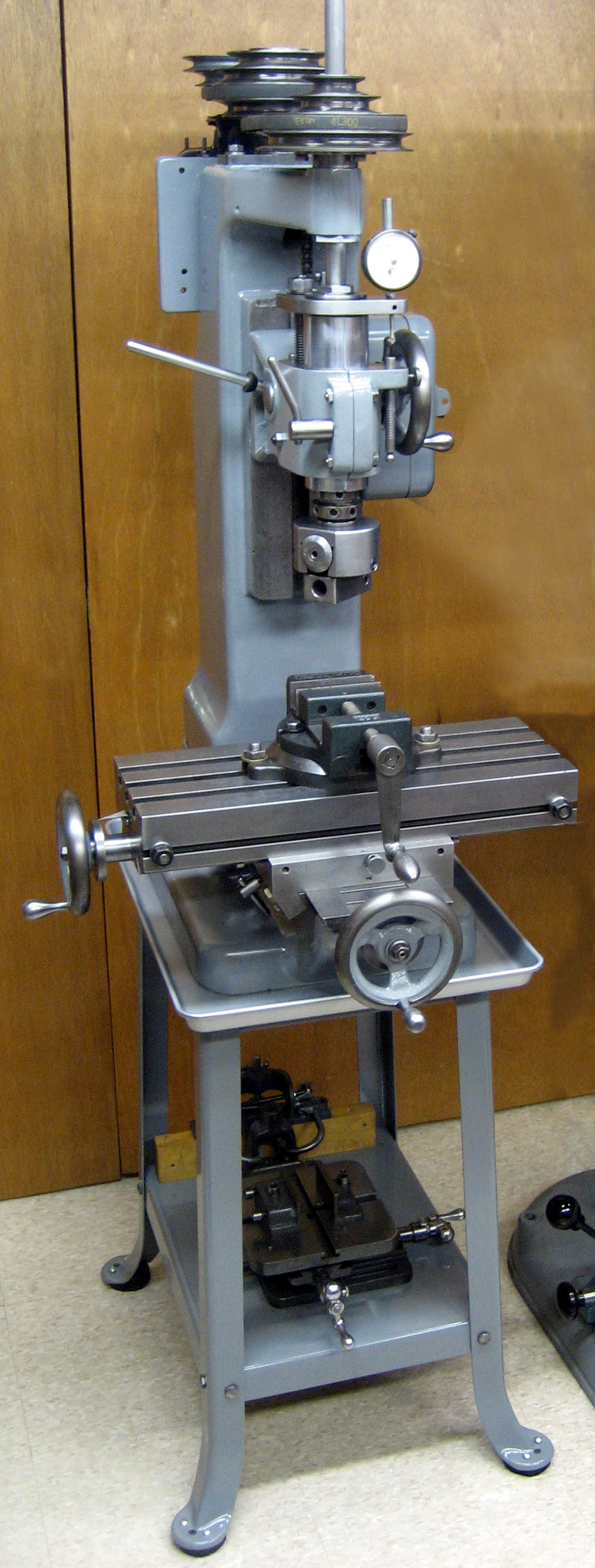
Linley Jig Borer in its final and most desirable form - the post 1963 Mk. 1A
|
|
|
|
|
|
|
|
|
|
|
 |
|
|
|
|
|
|
The zeroing micrometer dials on all three axes of the later machines were a massive 5-inches in diameter. The scale was engraved around the full diameter of the handwheel and furnished with both a 0.0001" vernier scale and a beautiful satin-chrome finish. With a distance between the 100 graduations of 0.157 inches accurate readings could be taken without recourse to a magnifying glass.
|
|
|
|
|
|
|
|
 |
|
|
|
|
|
|
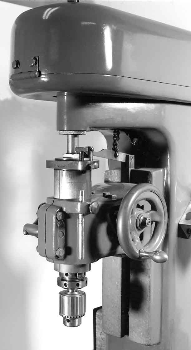
Linley Mk. 1A with the first type of power down-feed spindle
|
|
|
|
|
|
|
|
|
|
|
 |
|
|
|
|
|
|
In order to ease the operator's workload on boring operations the head was fitted with a very useful Direct-reading Micrometer Depth Gauge with a graduated bar passing through a boss on the side of the casting. Its method of operation was simple: to machine to a depth of 1.167 inches the cutting tool was set in contact with the work and the bar moved until it was at any even line. The stop-screw was then lowered until it made contact with the top of the bar - and locked. The dial was set to zero, locked and then the bar lowered 11 divisions; the cut could now be made until the stop-screw was met. If the stop-screw was then released the remaining distance of 0.067" could be accurately measured by using the large and clear down-feed dial.
|
|
|
|
|
|
|
|
|
|
|
 |
|
|
|
|
|
|
Linley had offered a down-travel-only power-feed head as an optional extra for some time, but with the coming of the 1A it was made standard - though, no doubt, they would not have refused to sell one without. The feed was taken from a belt-drive arrangement within the head, via a clutch, to an enclosed gearbox which provided a drive of 0.0015" per revolution of the spindle; an automatic-disengage mechanism was included. By 1964 the feed had been modified to produce a power movement in both directions, and it was this style of gearbox that was used on the copy built by the Downham (and later by Elliott) in England.
One problem that may be encountered with a well-used machine is play in the guide keys where the spindle runs through the top drive pulley. If the machine has the power down-feed the drive shaft has to be taken out first - just loosen the set-collar and slide the shaft up and out. (However, be careful, there is a small key inside the drive assembly that will fall out, loose it and the drive won't work. If it does drop free replacement is easier if the top is taken off the swivelling part of the drive unit, the worm gear removed and assembly carried out in reverse order). After lifting off the top cover and belts remove the 3 recessed Allen-head screws under the spindle drive pulley (there is a sliding stop that is pushed up to hold the pulley from turning while loosening the screws) and the pulley will slide up the spindle and off.
Made from standard 3/16" x 1/4" key-steel stock, the guide keys are can be replicated using only hand tools and a degree of care.
|
|
|
|
|
|
|
|
|
|
|
|
|
|
 |
|
|
|
|
|
 |
|
|
|
|
|
|
In later years, the option was offered of a mechanical variable-speed drive from a 220v AC 3-phase motor running at a constant 1200 rpm - the unit being standard on the version of the Linley marketed using the Boyer-Schultz name. The rather large unit was entirely self-contained (it simply bolted into the place normally occupied by the standard motor) and used the traditional type of expanding and contracting pulley system. The plate affixed to the unit gave a speed range of 283 to 2840 rpm, but by the time the drive reached the spindle via a standard V belt - which could be positioned on one of two differently-sized pulleys - this had changed to 110 to 3000 rpm. Speeds were altered by turning a large handle on the right-hand side of the unit..
|
|
|
|
|
|
|
|
 |
|
|
|
|
|
|
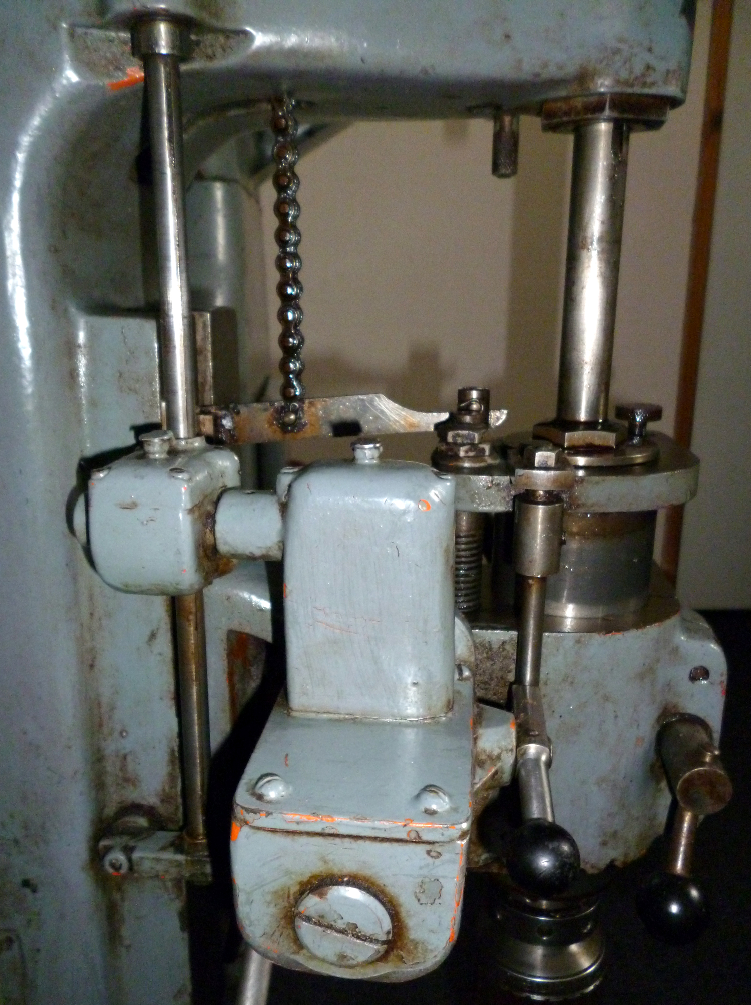
Left-hand side of the Power-feed head on the very similar English-made "Elliot Mini Jig Borer". In this case the power feed was in both directions, unlike the pre-1964 Linley installation which worked on down-feed only.
|
|
|
|
|
|
|
|
|
|
|
 |
|
|
|
|
|
|
Right-hand side of the Power-feed head on the Elliot Mini Jig Borer.
The head was fitted with a very useful Direct-reading Micrometer Depth Gauge - its graduated square bar can seen passing through a boss on the side of the casting.
It's method of operation was simple: to machine to a depth of 1.167 inches the cutting tool was set in contact with the work and the square bar moved until it was at any even line. The stop screw was then lowered until it made contact with the top of the bar - and locked. The dial was set at zero, its setting locked, and the bar lowered 11 divisions. The cut could now be made until the stop screw was met; this was then released and the remaining 0.067" fed in using the dial.
|
|
|
|
|
|
|
|
|
|
|
|
|
|
|
|
|
 |
|
|
|
|
|
|
The saddle assembly, micrometer dials and rulers on the Elliott all differed in detail - even in comparison with the original Linley Mk. 1
|
|
|
|
|
|
|
|
|
|
|
 |
|
|
|
|
|
|
Because the machine was in three sections - base cabinet, knee section and main column - it was possible to introduce a distance piece between the two upper parts and so increase the spindle to table distance by around 4 inches.
|
|
|
|
|
|
|
|
 |
|
|
|
|
|
|
The original table had narrow ways and a lock that acted directly on the gib strip, so moving the table slightly when it was tightened - not a situation that is welcome in the construction of a jig borer. The picture below shows how the makers tackled the problem with slightly wider ways and a modified lock which secured the table without moving it.
|
|
|
|
|
|
|
|
|
|
|
|
|
|
 |
|
|
|
|
|
At some point during the production of the original machine, the table ways were made slightly wider and fitted with what the makers called a "flexible-blade, non-influencing type table lock" the function of which was to "prevent longitudinal movement whilst absorbing any lateral pressure from the lock screws." The table was also fitted with finely-engraved rulers.
|
|
|
|
|
|
|
|
 |
|
|
|
|
|
|
|
|
|
An early Mk. 1 head without power down-feed.
|
|
|
|
|
|
|
|
|
|
 |
|
|
|
|
|
|
Beautifully restored by David Harding in the USA, this late model Linley 1A has both
the desirable variable-speed spindle drive and the massive power down-feed unit.
|
|
|
|
|
|
|
|
|
|
|
|
|
|
 |
|
|
|
|
|
|
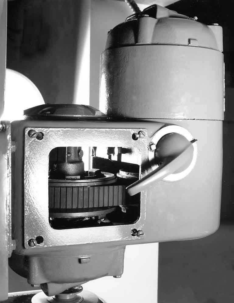
Inside the mechanical variable-speed drive unit showing the 1-inch wide transmission belt between the expanding and contracting pulleys.
|
|
|
|
|
|
|
|
 |
|
|
|
|
|
|
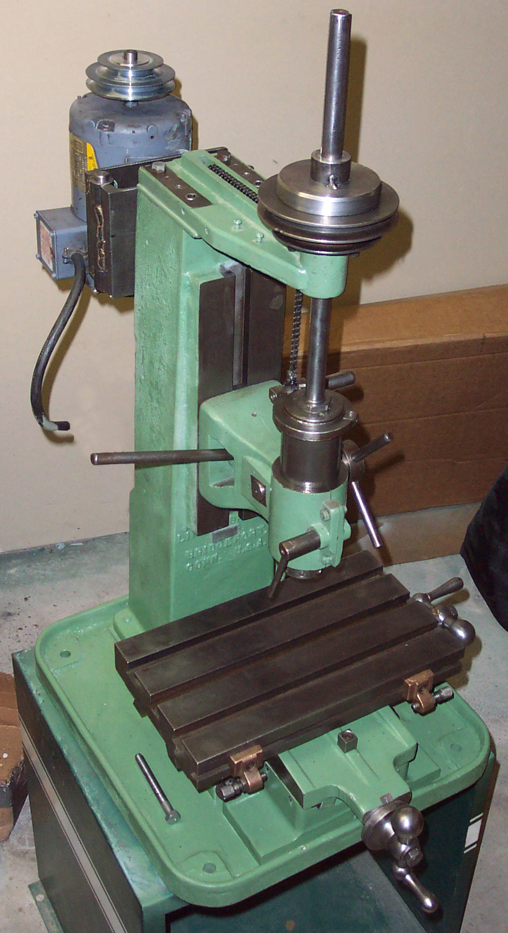
Although missing its original belt guard and motor mount
this very early Linley appears to be otherwise complete
|
|
|
|
|
|
|
|
 |
|
|
|
|
|
|
|
|
|
|
|
 |
|
|
|
|
|
|
A rebuilt Linley complete with that essential jig borer accessory a micrometer boring head - in this case adapted from a Bridgeport
|
|
|
|
|
|
|
|
|
|
|
|
|
|
|
|