 |
|
|
|
|
|
|
|
|
|
|
|
|
|
|
|
|
|
|
|
|
|
|
|
|
|
|
|
|
|
|
|
|
|
|
|
|
|
|
|
|
|
|
|
|
|
|
|
|
|
|
|
|
|
|
|
|
|
|
|
|
|
|
|
|
|
|
|
|
|
|
|
|
|
|
|
|
|
|
|
|
|
|
|
|
|
|
|
|
|
|
|
|
|
|
|
|
|
|
|
|
|
|
|
|
|
|
|
|
|
|
|
|
|
|
|
|
|
|
|
|
|
|
|
|
|
|
|
|
|
|
|
|
|
|
|
|
|
|
|
|
|
|
|
|
|
|
|
|
|
|
|
|
|
|
|
|
|
|
|
|
Founded in 1873, John Lang & Sons was based in Mary Street, Johnstone, near Glasgow. At first their operations, like many contemporary firms in this once thriving industrial area, included a variety of products and services including the manufacture of gears (a specialism that was to last until their closure) shapers, horizontal borers, the design and making of one-off machines and lathes. However, it was not long before lathes were to dominate output and, subsequently, the Company became famous for their wide range of high-quality, well-designed and effective machines that were regarded by many as superior to those manufactured by Dean, Smith and Grace - and equal to those from the better German makers. Although lathes made up the bulk of entries in the Company's catalogue, other items continued to be made including automatic tooth-rounding machines; heavy-duty tailstock revolving centres; mandrel and bench straightening presses; centring, counter-boring and facing machines; small pumps for oil or water and a multi-plate friction clutch branded "Jehu".
Lang were to remain an independent enterprise until taken over by Wickman in the 1960s, to become Wickman-Lang. Wickman were known for their automatic lathes and these had already been built at the Lang factory for some years before the take over. Both conventional and automatic types (the former in decreasing numbers) were built at the Lang factory until the John Brown Engineering Group, who owned Wickman, closed the factory in 1979. A small offshoot, Lang Power Chucks, managed to survived until the mid-1980s.
Amongst the huge variety of regular production and special-order Lang lathes manufactured (including the ever-popular Junior) was the A4, a type made during the 1960s and built as a conventional centre lathe with a choice of three centre heights: 18", 21" and 25" (914 mm, 1067 mm and 1270 mm). The two smaller models were available with a straight or gap beds - but only a rigid, straight construction on the longest. When specified with a gap the biggest job that could be turned on a faceplate was 48"(1219 mm) in diameter and up to 17" (432 mm) thick. Also offered was the CA4, a production version with a short bed carrying a either a square or hexagon turret and a headstock with plain or roller bearings that, like the standard model, was available in two distinct forms - these being described below.
All versions could be had in a variety of bed lengths, the smallest listed having a between-centres capacity of 70" (1778 mm) and then, at intervals of 24" (610 mm), any length desired up to a maximum of 21' 10" (6655 mm) - these figures allowing for the use of the recommended, heavy-duty rotating tailstock centre. At its longest the 26.26-inch (667 mm) wide bed was a hefty one-piece unit some 31-feet long and, like all the Company's castings, was produced in a close-grained iron that had been subjected to stringent metallurgical controls and poured in-house from a Lang designed and operated melting unit.
Fitted with "inverted-V" and flat ways together with a narrow front vertical way to guide the saddle, the hardened beds were either hand scraped or ground according to their length and supported on intermediate plinths of large box-section design equipped with levelling screws and foundation bolts. Surrounding the supports were loose, pull-out sheet-metal chip and coolant collection trays - though when the 50-inch swing model was ordered the bed was made full depth to the floor, the support plinths eliminated and coolant collecting ducts arranged in the concrete foundation.
Continued below:
|
|
|
|
|
|
|
 |
|
|
|
|
|
|
Lang A4 lathe
Continued:
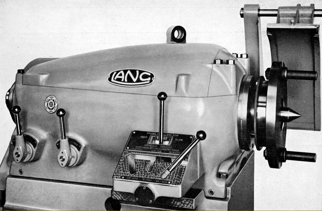
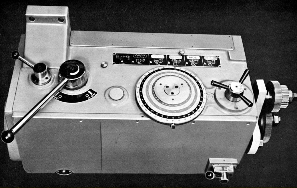
Of massive construction and clean lines, the headstock was available in two versions: "Standard" and "External Gear Drive to the Chuck". The former held a spindle bored through 6.125" (155 mm) and running in plain, white-metal lined bearings - the front 8.5" in diameter and 8.5" long (216 x 216 mm) and the rear 7.5" and 6.5" (190 x 165 mm) respectively. Driving the spindle was a cluster of nickel-chrome steel gears, heat treated to 100 tons per square inch, profile ground and running on solid splined shafts running in ball races. Lubrication was automatic by a pressure pump delivering filtered oil to a trough formed in the top of the headstock from where it was piped to the bearings and gear-mesh points. To ensure not even he smallest particle of debris could damage the spindle bearings, a supply was taken from the main filtered supply and directed to them on a closed circuit. Using the standard specification Lang quick-release spindle-nose fitting, concentricity of fittings so mounted was maintained by a short taper. Control of the twelve spindle speeds was by the juxtaposition of two levers, one selecting the high or low range, the other a particular speed - these being, with the input pulley running at 500 r.p.m., 5.5, 7, 11, 16, 22, 31, 45, 68, 96, 134, 196 and 275 r.p.m. If the input pulley was arranged (by changing motor pulley for a smaller one) to run at 600 r.p.m. the spindle speeds became 6.5, 9.5, 13, 19, 27, 38, 56, 82, 115, 235 and 330 r.p.m.
Offered as an option for very heavy-duty work - though making it unable to tackle as wide as variety of work as the "Standard" - the "External Gear Drive to the Chuck" headstock was reminiscent of the so-called "double" and "treble" backgear systems used on some pre-WW2 lathes including models by Bradford, D.W.Pond, Harrington and one much earlier example, by Fay & Scott, that used a very similar layout to that on the Lang though with cone pulleys and flat-belt drive.
Almost identical inside to that on the Standard, the External Gear Drive headstock had twelve speeds with the six highest obtained by the internal gearing but the six lowest through an external gear, protruding from the inside front face of the headstock, that engaged with a ring gear mounted on the back of the independent 4-jaw chuck - this being permanently fitted to the spindle. The maker offered the option of pulley sets to give a choice of four input speeds: 400, 500, 600 and 800 r.p.m., the slowest of these producing spindle speeds of 2, 3, 4.5, 6.25, 9, 12.75, 17.5, 25, 35, 50, 72 and 100 r.p.m. The other input speeds gave, of course, proportional increases with the fastest set being 4, 6, 9, 12.5, 18, 25, 35, 50, 70, 100, 144 and 200 r.p.m. Although the same type of plain spindle bearings were used as on the "Standard" and with the same rear bearing, in order to absorb the great loading associated with the sort of work the lathe was able to undertake the front was made considerably larger being some 10" in diameter and 10" long (254 x 254 mm).
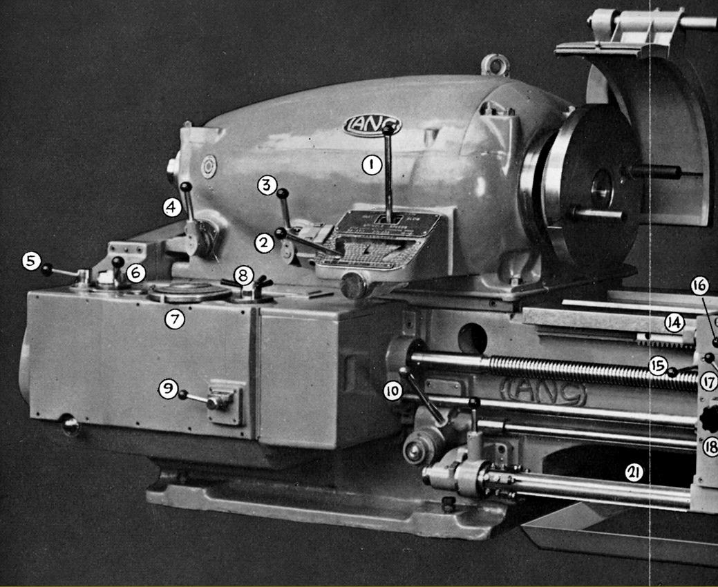
Although power normally came from a 22.5 kW (30 h.p.) motor sitting behind the headstock on an adjustable plate, should this installation have proved difficult for the customer, the makers offered a mounting that placed the motor at the end of the lathe, so simply increasing its length. Electrical stop, start and reverse of the spindle (once the necessary push-buttons had switched on the electricity supply) was by two lift and lower levers, one mounted just to the right of the screwcutting gearbox and within easy reach of the operator's normal working position and another pivoting from the right-hand face of the apron and so moving with it.
Continued below:
|
|
|
|
|
|
|
|
|
|
|
|
 |
|
|
|
|
|
|
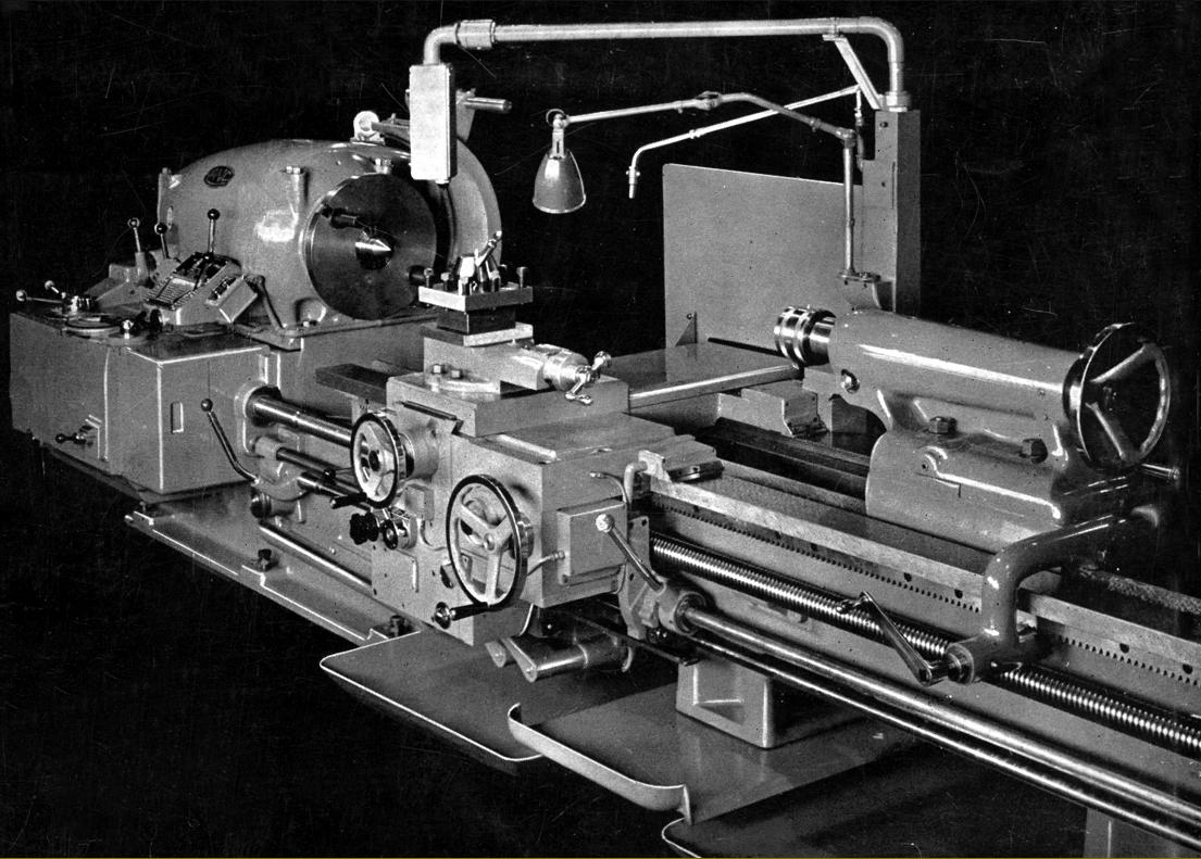
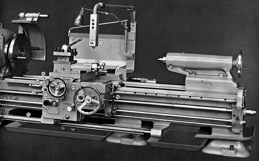
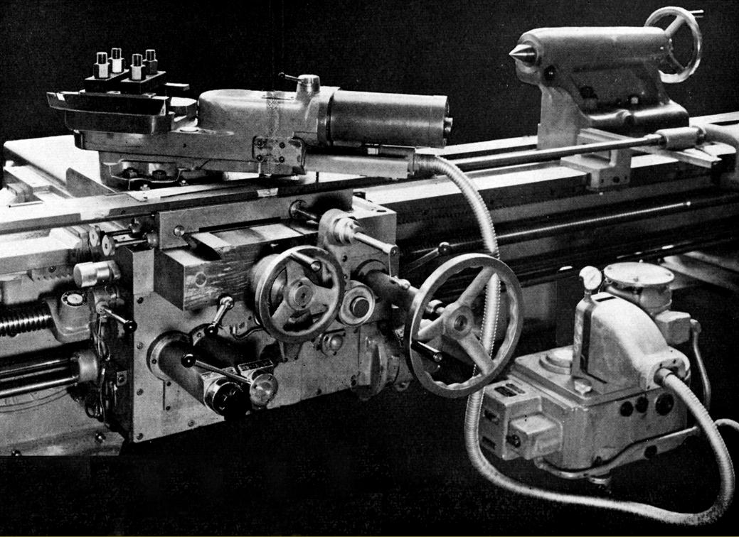
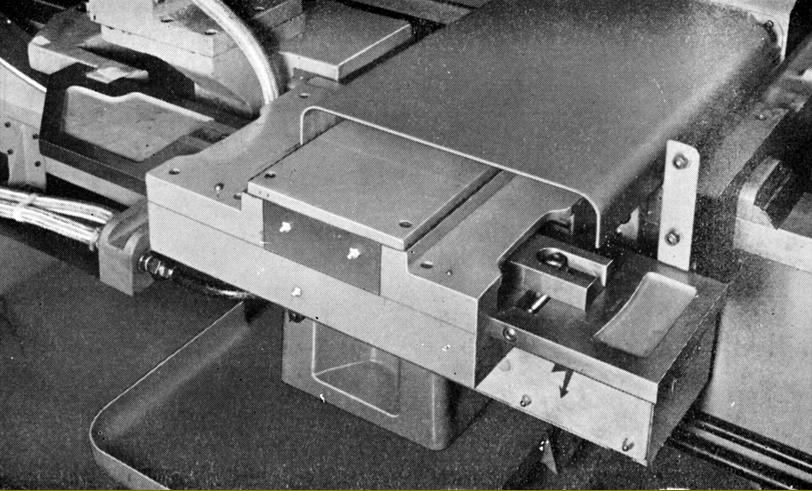
Lang A4 fitted with optional automatic, multi-stop disengage to the carriage drive (Item 21)
|
|
|
|
|
|
|
|
|
|
|
|
Continued:
Using a 2.5-inch diameter, 1/2-inch pitch leadscrew with compensating thrust bearings fitted at each end (the idea being to reduce to a minimum any periodic error caused by end float) screwcutting (and power feeds) were from a totally enclosed gearbox that had not only its gears and bearings lubricated by a pressure-fed supply of oil, but the also the changewheels and connecting gears. Control was by levers in combination with a direct-reading dial with a standard range of 36 pitches and feeds available; however, as well as those marked on the dial, an additional 36 coarse feeds (at 4 times the normal rate) could be selected at the lowest six spindle feeds and 36 fine feeds (at 0.45 times the normal rate) when running on the six highest speeds. To further extend the range, all feeds could be halved or double by apron-mounted gearing - this giving a total of 324 feeds from a slowest (sliding) of 0.008" to a fastest of 0.416" (0.02 to 10.56 mm) per revolution of the spindle. Cross feed rates were (as usual) set to be automatically at half those for longitudinal. In order to save wear on the bearings, when not in use the leadscrew could be disengaged from the screwcutting gearbox and just the power-shaft left running. When the external gear drive to the chuck was fitted - and in order to allow really heavy cuts to be taken - the coarse rates were set at 8 times the standard rate and the facility to take extra-fine feeds omitted.
Normal screwcutting generated 36 threads per inch from 2 to 28 with a coarse range (ratio 4 to 1) from 1/2 to 7 t.p.i.; standard metric pitches produced were 30 from 1 to 14 mm with a coarse range (ratio 4 to 1) from 4 to 56 mm; 24 Module pitches from 0.5 to 7 with a coarse range (ratio 4 to 1) 2 to 28 and 34 Diametral pitches from 4 to 56 with a coarse range (ration 4 to 1) from 1 to 14.
Sitting on flat and inverted-V ways the saddle was equipped with hardened replacement steel strips on its underside and aligned to the bed by a narrow front vertical strip with the clearance able to be set by a full-length tapered gib strip. All faces were lubricated under pressure from the same pump that served the apron while swarf and dirt were excluded by spring steel scrapers and plastic wipers. Conventional in design the compound slide rest assembly on the two smaller models had a cross slide with a travel of 24" (610 mm), though this was reduced to a less useful 18" (457 mm) when a taper-turning attachment was fitted; held down with four bolts the top slide had a travel of 8" (203 mm). The 50-inch version was modified to make the most of its extra capacity with the cross slide having a travel of 28" (711 mm) both with and without taper turning and a top slide travel of 16" (406 mm). The zeroing micrometer dials were large, crisply engraved and given a satin chrome-plate finish. Fitted as part of the standard equipment was an indexing 4-way toolpost with a maximum tool-holding capacity of 1.5" x 1.25" (38 x 32 mm); indexing was by a simple, positive location using a plunger that could be located in four "cups", all the parts being hardened and ground. In place of the 4-way, the makers offered what was once a popular fitting on larger United Kingdom lathes, a "four-bolt" type with each pair of bolts holding a separate rectangular steel blocks supported on light springs.
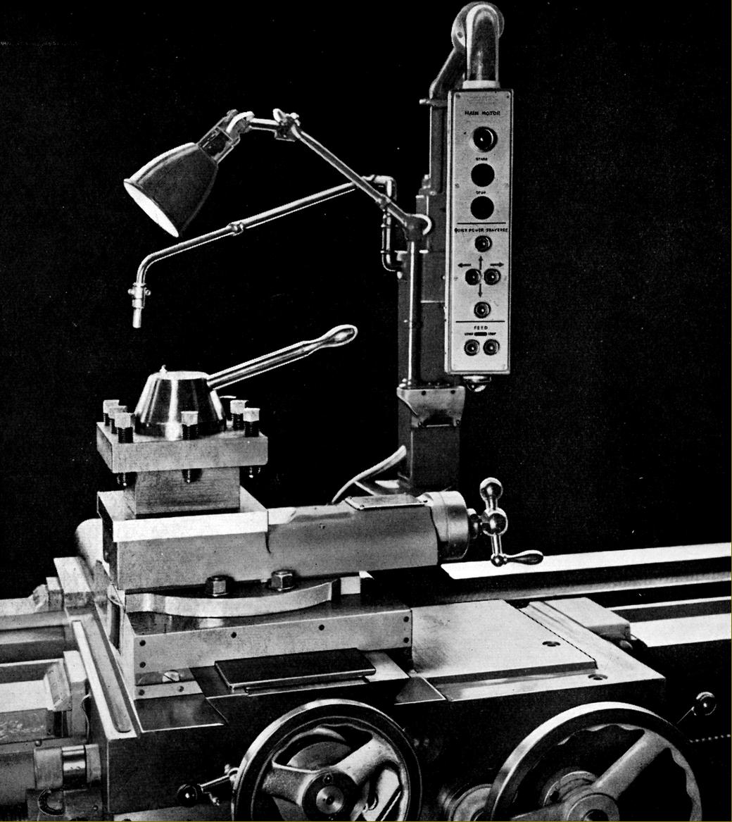
Attached to the carriage was pendant-supported electrical box, adjustable for position and able to be swung out of the way when loading the lathe. Control was by push buttons that operated the main motor 'stop' and 'start', sliding and surfacing feeds 'on' and 'off!' and the (optional-extra) four-way quick power traverse. To show the state of the electrical system red and green lights were provided that indicated, respectively, power to the main and feeds motors were "on" or "off".
Hardly a good-looking affair with its exposed oil pipes, the apron was, nevertheless, a workman-like job being totally enclosed and double-walled with the sump oil supply being pumped under pressure to all bearings and gears and, when in use, the leadscrew clasp nuts as well. Selection of power sliding and surfacing feeds was by a lever with engagement and disengagement using and instantly responding magnetic clutches mechanism, their control being by push buttons on the pendant control box. One option (and very useful on such a large lathe) was an electrically-driven, four-directional rapid-feed mechanism, the 1 h.p. electric motor being flange-mounted against the right-hand face of the apron. When engaged, the feed caused the carriage to move at 15 feet (4572 mm) per minute and the cross slide at 3 feet (914 mm) per minute As an essential safety feature an electrical interlock prevented engagement of the cross-feed drive until its handwheel and been disengaged.
Two tailstocks were offered an ordinary type, repositioned by hand-operated gearing working on the bed-mounted carriage rack and a much more massive very heavy-duty type that was the standard equipment on the 50" swing lathe and available as an option on the 36" and 42" models. Both types had massive No. 7 Morse taper rams that were cyanide hardened on their nose with the smaller of the two supplied with both a fixed and revolving centres. In order to move its considerable weight, the heavy-duty tailstock had a 3:1 reduction gearbox built into the hand-operated rack-and-pinion drive - this mechanism incorporating a positive lock when the handle was released that acted as an addition thrust stop to compliment the ordinary bed lock. The ram on this version was driven by a forwards facing, full-circle handwheel working through 2.2:1 reduction gearing and was supplied with either a Morse taper socket or a permanently-mounted rotating centre.
A number of options was offered including hydraulically-operated coping equipment that could profile externally or internally; taper turning with a capacity of 20" x 20° (508 mm x 20°); an extended cross slide with T-slots and the ability to mount, on raiser blocks, the normal top alide as well as a rear-mounted parting-off toolpost and automatic tool retraction device to permit high-speed screwcutting - the tool being automatically withdrawn at the same point on each pass so giving the operator time to disengaged the leadscrew clasp nuts..
|
|
|
|
|
|
|
|
|
 |
|
|
|
|
|
|
|
|
|
 |
|
|
|
|
|
|
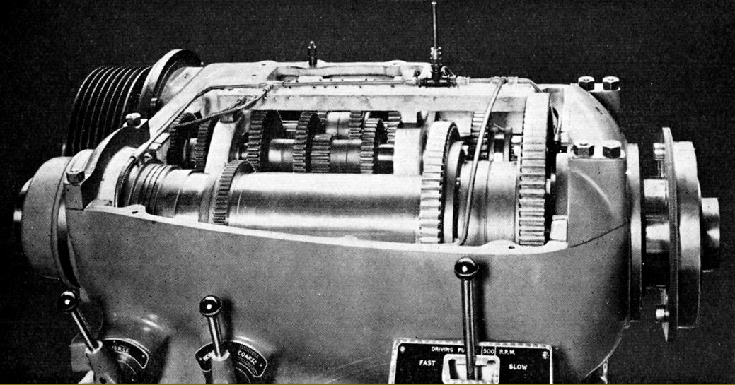
Of massive construction and clean lines, the headstock was available in two versions: "Standard" - shown above - and the "External Gear Drive to the Chuck" type. The "Standard" held a spindle bored through 6.125" (155 mm) and running in white-metal lined plain bearings - the front being 8.5" in diameter and 8.5" long (216 x 216 mm) and the rear 7.5" and 6.5" (190 x 165 mm).
|
|
|
|
|
|
|
 |
|
|
|
|
Interior of the "Standard" headstock showing some of the oil-distribution pipework
|
|
|
|
|
|
|
 |
|
|
|
|
|
|
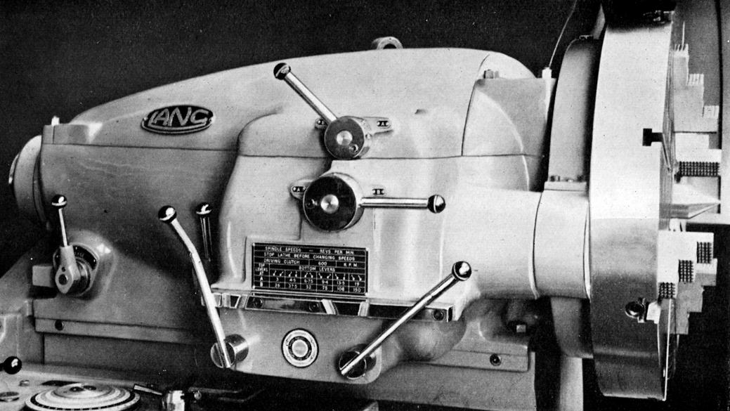
"External Gear Drive to the Chuck" headstock. Identical in internal construction to that on the Standard model this extra-heavy-duty headstock had twelve speeds with the six highest obtained by the internal gearing but the six lowest through an external gear, protruding from the inside front face of the headstock, that engaged with a ring gear mounted on the back of the independent 4-jaw chuck - this being permanently fitted to the spindle.
|
|
|
|
|
|
|
 |
|
|
|
|
|
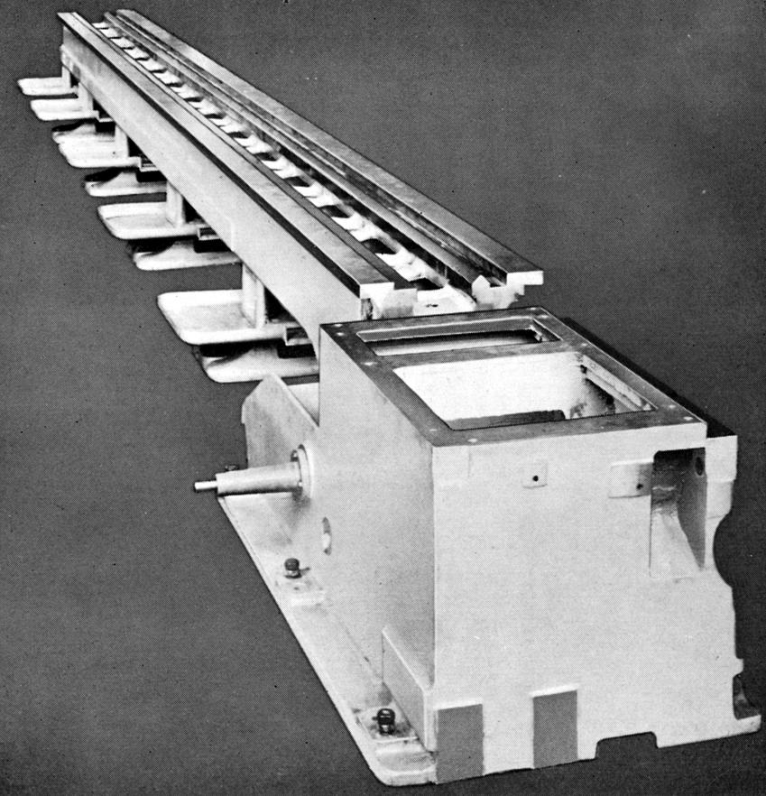
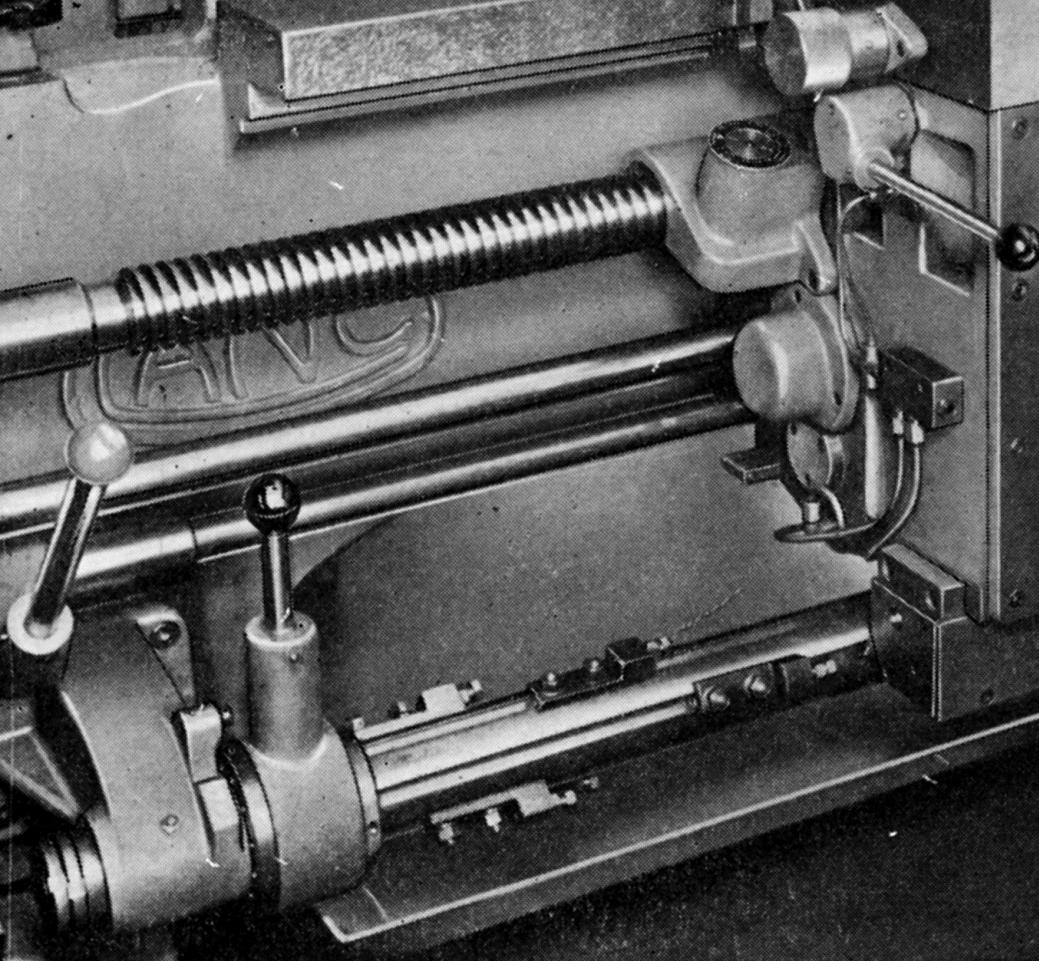
Machined with "inverted-V" and flat ways together with a narrow front vertical way to guide the saddle, the hardened beds were either hand scraped or ground according to their length and supported on intermediate plinths of large box-section design equipped with levelling screws and foundation bolts. Surrounding the supports were loose, pull-out sheet-metal chip and coolant collection trays - though when the 50-inch swing model was ordered the bed was made full depth to the floor, the support plinths eliminated and coolant collecting ducts arranged in the concrete foundation.
|
|
|
|
|
|
|
|
|
|
|
|
 |
|
|
|
|
|
|
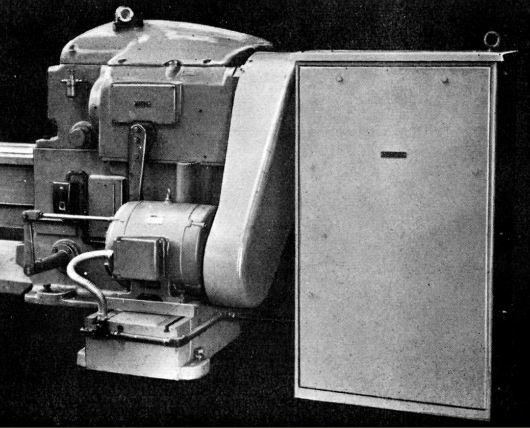
Although power normally came from a 22.5 kW (30 h.p.) motor sitting behind the headstock on an adjustable plate, should this installation have proved difficult the makers offered a mounting that placed the motor at the end of the lathe, so simply increasing its length.
|
|
|
|
|
|
|
 |
|
|
|
|
|
|
with not only the gears and its bearings but the also the changewheels and connecting gears lubricated Power feeds and screwcutting (by a 2.5-inch diameter, 1/2-inch pitch leadscrew) were from a totally enclosed gearbox by a pressure supply. Control was by a levers in combination with a direct-reading dial with a standard range of 36 pitches and feeds available; however, as well as those marked on the dial 36 coarse feeds (at 4 times the normal rate) were available at the lowest six spindle feeds and 36 fine feeds (at 0.45 times the normal rate) at the highest six speeds.
|
|
|
|
|
|
|
 |
|
|
|
|
|
|
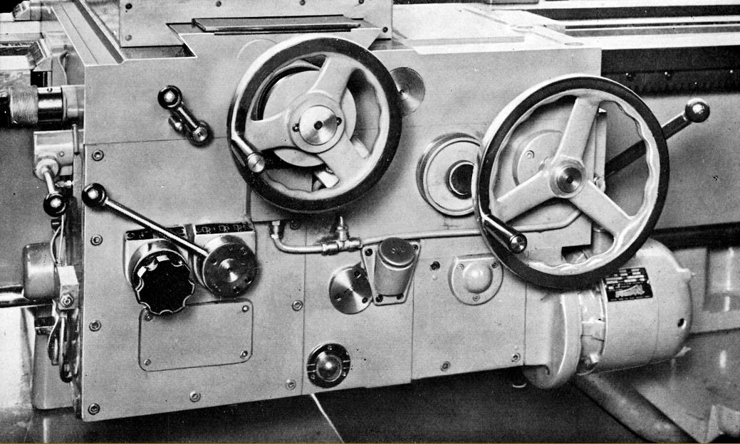
Hardly a good-looking affair with its exposed oil pipes, the apron was, nevertheless, a workman-like job being totally enclosed and double-walled with the sump oil supply being pumped under pressure to all bearings and gears and, when in use, the leadscrew clasp nuts as well.
The apron shown above has the rapid-return feeds mechanism fitted, the electric motor being flange-mounted against the right-hand face.
|
|
|
|
|
|
|
 |
|
|
|
|
|
|
Attached to the carriage was pendant-supported electrical box, adjustable for position and able to be swung out of the way when loading the lathe. Control was by push buttons that operated the main motor 'stop' and 'start', feeds 'on' and 'off', the (optional-extra) four-way quick power traverse. To show the state of the electrical system and red and green lights were provided to indicate that, respectively, power and quick-return feeds (when fitted) were "on".
|
|
|
|
|
|
|
|
|
|
|
|
 |
|
|
|
|
|
|
Hydraulic copying slide with a Dixon quick-set toolpost
|
|
|
|
|
|
|
 |
|
|
|
In place of the standard indexing 4-way toolpost the makers offered what was once a popular fitting on larger United Kingdom lathes, a "four-bolt" type with each pair of bolts holding a separate rectangular steel blocks supported on light springs.
|
|
|
|
|
|
|
|
|
 |
|
|
|
|
|
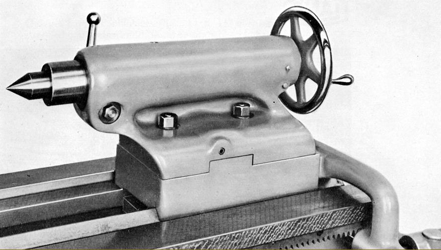
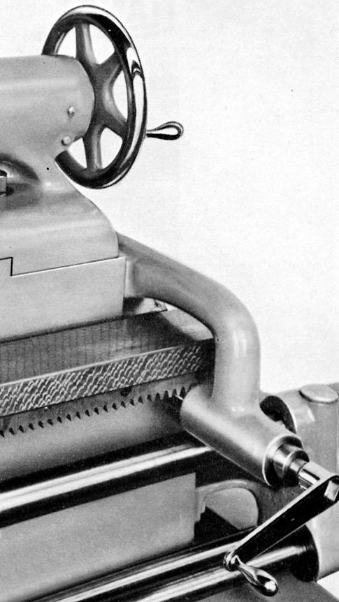
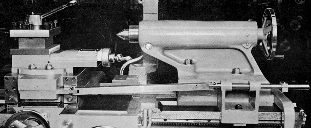
Standard tailstock with a massive No. 7 Morse taper socket and a hand-operated, rack-feed mechanism to allow easy repositioning
|
|
|
|
|
|
|
 |
|
|
|
|
|
|
|
|
|
|
|
|
|
|
|
 |
|
|
|
|
|
|
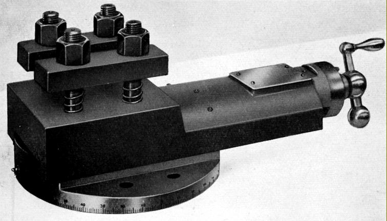
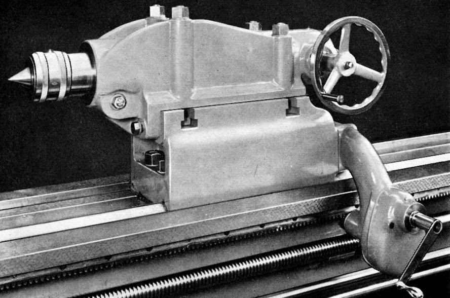
Very heavy-duty No. 7 Morse taper tailstock fitted as part of the standard equipment on the 50" swing lathe and available as an option on the 36" and 42" models. Note the 3:1 reduction gearbox built into the hand-operated rack-and-pinion drive; the box incorporated a positive lock when the handle was released this acting as an addition thrust stop to compliment the ordinary bed lock. The spindle could be provided with either a Morse taper socket or a permanently-mounted rotating centre.
|
|
|
|
|
|
|
 |
|
|
|
|
|
|
One very useful extra was a six-stop unit for the longitudinal feed. The stop bar, mounted along the front of the bed, was rotated by a quick-action lever ratchet with the 12 indexed positions giving 6 stop locations and 6 neutral. On all bed length the unit was limited to a carriage travel of up to 72" (1829 mm) from the headstock.
|
|
|
|
|
|
|
 |
|
|
|
|
|
|
Operated by a stylus-controlled, hydraulic unit the profiling slides could be swivelled to any angle and the fitted four-bolt tool slide turned to suit the angle of the profiling slide in relation to the axis of the lathe. A retraction valve, mounted on the top of the hydraulic cylinder, controlled the movement of the profiling slide when the stylus was not in contact with the template. The template holder accommodated both longitudinal and surfacing templates and was supported by an adjustable auxiliary slide, arranged at the front of the saddle, fitted with a micrometer adjustment for the surfacing template setting. Fixed to the front shear of the bed at the tailstock end was an anchor bracket used to supported the template holder and its integral micrometer adjustment screw, this being used to set the longitudinal adjustment and joined to the holder by a connecting rod.
It was recommended that templates should not be less than -1%" (4-75 mm.) thick. As the minimum distance from the template holder location face to the centre line of the stylus altered with the angle of the profiling slide the width of the template had, therefore, to be made to suit. For the profile turning of radial surfaces or similar shapes, the profiling slide was set at right angles to the lathe axis. If square shoulders were to be copied, the normal angle of the slides was set at 45° but, according to the job in question, it might have been necessary to set the slides at some other angle. The cutting speed of the saddle was dependent on the angle of the profiling slides but, whatever the angle, the saddle speed was not allowed to exceed 90% of the profiling slide speed i.e. 90% of 50" per min (1270 mm. per min)
It was also possible to undertake profile boring, the method being identical to that for profile turning save that direction of the job was run in reverse and, of course, the cutting tool arranged to meet the work on the opposite side of the lathe axis.
An adjustable retraction stop on the profile slide was fitted to ensure that, as the boring bar was withdrawn from its cut, it did not accidentally hit the opposite side of the bore. The pump set - motor, accumulator and tank - was mounted on wheels for ease of movement.
|
|
|
|
|
|
|
|
|
|
|
|
 |
|
|
|
|
|
|
Automatic tool retraction attachment. This rod-and-lever-operated unit allowed the cutting to be withdrawn at the same point on each pass - thus giving the operator time to disengage the leadscrew clasp nuts and wind the carriage back to the start point
|
|
|
|
|
|
|
 |
|
|
|
|
|
|
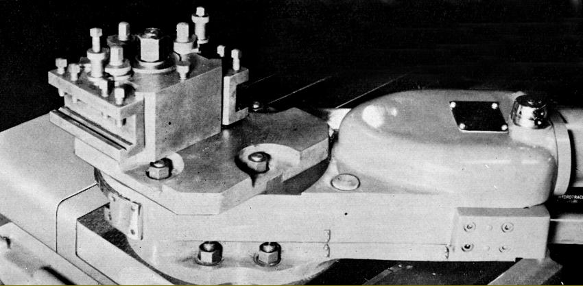
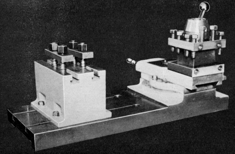
Extended cross slide with T-slots and the ability to mount, on raiser blocks, the normal top alide as well as a rear-mounted parting-off toolpost
|
|
|
|
|
|
|
 |
|
|
|
|
|
|
|
|
|
|
|
|
|
|
|
 |
|
|
|
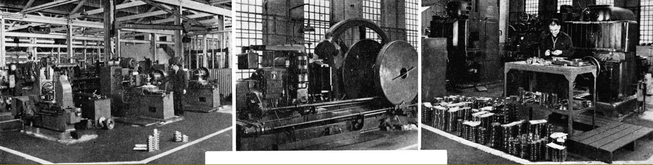
Worm wheel hobbing machines
|
|
|
|
|
|
|
|
Work done on Red Ring gear shaving machines
|
|
|
|
|
|
|
|
Sunderland gear planing machines
|
|
|
|
|
|
|
|
|
|
|
 |
|
|
|
|
|
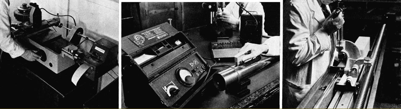
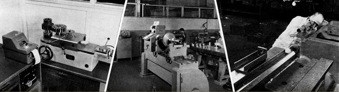
Profilometer surface finish tester
|
|
|
|
|
|
|
Goulder involute profile testing machine
|
|
|
|
|
|
|
|
|
|
|
 |
|
|
|
|
|
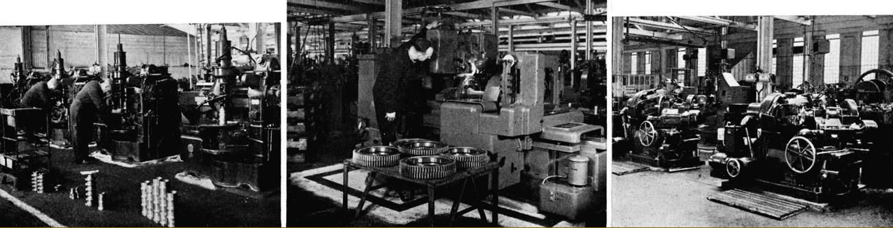
Maag and Orcutt gear grinding machines
|
|
|
|
|
|
|
Fellows gear shaping machines
|
|
|
|
|
|
|
|
|
|
|
 |
|
|
|
|
|
Acme thread whirling of a leadscrew
|
|
|
|
|
|
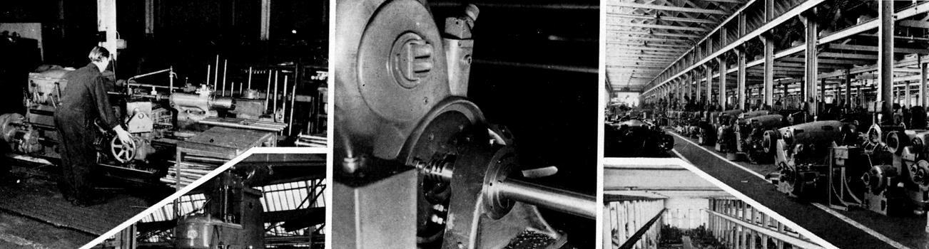
Batch production of shafts on a Lang profiling lathe
|
|
|
|
|
|
|
|
|
|
 |
|
|
|
|
|
Milling saddle cover recesses
|
|
|
|
|
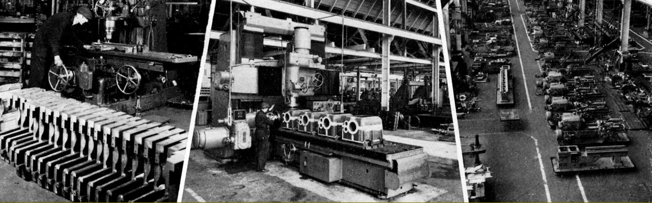
Gang milling headstock castings
|
|
|
|
|
|
|
|
|
|
 |
|
|
|
|
|
Gear concentricity testing on a Goulder gear tester
|
|
|
|
|
Machine for balancing drive shafts
|
|
|
|
|
|
|
|
|
|
 |
|
|
|
|
|
|
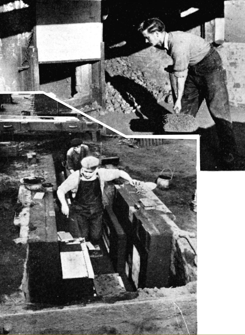
Flour moulding for a long-bed lathe
|
|
|
|
|
|
|
|
|
|
|
|
|
|
|