|
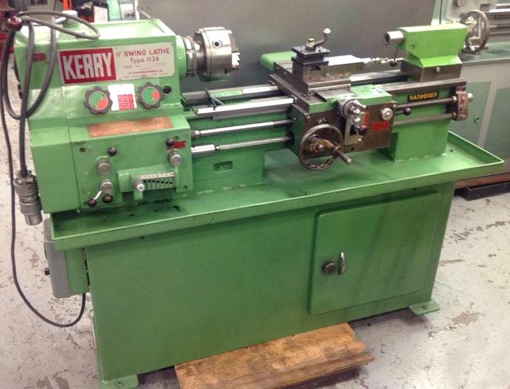
Although the "Mk. 5" Kerry 11" and 13" lathes (models 1124/1140 and 1324/1340) were greatly changed from their immediate forebears, both their general specification and many of the detail fittings remained the same. The two sizes of lathe were, apart from the centre height and the associated alterations to the headstock, tailstock and tool-slide castings, identical in all respects. The model numbers refer of course to the swing and distance between centres: respectively 11 inches and 24 or 40 inches for the 1124/1140 and 13 inches and 24 or 40 inches for the 1324/1440.
For a 5.5" lathe the bed was of massive proportions, heavily ribbed between the walls and carrying a Vee and flat for the saddle and another Vee and flat for the No. 3 Morse taper tailstock. It was manufactured from a seasoned iron casting that was first rough machined to break the external skin; this was followed by a series of heat treatments to relieve internal stresses before final machining. The bed was then hardened and finally ground to its finished dimensions.
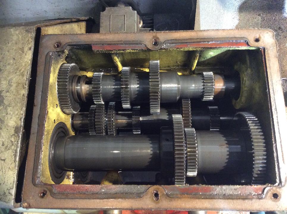
All-geared, the headstock had three shafts that carried gears, of which only two pairs were engaged on the six highest speeds; neither the main spindle, nor the drive input shaft, had any sliding gears to wear and rattle. The number speeds was increased from eight to nine and were more evenly spaced at 45, 75, 115, 200, 325, 500, 600, 1000 and 1500 rpm. Two traditional, Kerry-style knobs selected the speeds and the sliding gears operated by these dials were on a single, multi-splined shaft. All gears in the headstock were manufactured from nickel-chromium-molybdenum, heat-treated steel and, apart from the main spindle, all the shafts carrying them ran on ball bearings. As a neat, finishing touch, the headstock top was recessed to make a useful tool tray.
Hardened and ground the main spindle was bored 13/8" and ran on Timken taper roller bearings with the nose supplied with set-down sleeves to accept either a No. 3 Morse taper centre or a collet adaptor with a maximum capacity of 1". The spindle end fitting was a considerable improvement on the simple thread of the previous AG Series lathes being an American Long-nose taper type in an L00 size (the smallest available) that offered both improved rigidity and the facility to be reversed at high speed in complete safety.
Positioned, as on the earlier lathes, at the rear of the bed beneath the headstock, the 2 H.P. motor was mounted on a pivoted plate with open tee slots for belt-tension adjustment - set by means of a simple jacking screw. On some early AG lathes the clutch operating mechanism could prove troublesome - the operating rod passing longitudinally through the headstock cover casting with the whole assembly of rods and linkages being under-engineered for its purpose. The problem was solved by combining the use of a "Poly-V" belt (designed to combine the smooth-running advantages of a flat belt with grip of a multi-Vee drive) with headstock input shaft engineered to carry a combined cone clutch and brake unit (mounted inside the headstock pulley) with the hardened male cone bearing against a replaceable Tufnel insert. The new set-up completely eliminated the early problems with the whole assembly being more robustly built and the operating lever acting almost directly on the clutch mechanism.
Five gears were used on the train from headstock to screwcutting gearbox, including one made of a non-metallic material (probably Tufnol) to quieten the drive - if this gear is damaged, or missing, it should have 64 teeth. The screwcutting was fully enclosed, ran in an oil bath; there was an oil reservoir built into its upper section that allowed oil to trickle down felts into the bearings so protecting them from the ingress of metal particles. The external controls consisted of two levers, fitted to the left-hand section, that provided four changes of feed by operating gears sliding on splined shafts. The right hand section of the box contained 9 gears selected by a traditional sliding "tumbler selector" with a further lever (which replaced the action of tumble reverse) to select forward and reverse feeds. The gearbox therefore gave 36 changes of feed in both forward and reverse directions. By changing two change wheels, which were supplied as standard, 13 metric pitches could also be cut whilst additional gears were available to enable a wide variety of other pitches in Whitworth, metric, BA, etc., to be generated. A sliding dog clutch was fitted to the leadscrew, just outboard of its entry into the gearbox, that could be used to isolate the leadscrew drive when it was not needed. Both the leadscrew and feed-shaft were fitted with needle-roller bearings thrust washers housed in a heavy support block at the tailstock end of the bed. The leadscrew longitudinal end-float could be easily and finely adjusted by a screwed ring. The separate feed-shaft was hexagonal in section which was claimed to, but did not, eliminate the danger associated with keyways in rotating shafts grabbing loose clothing; to prevent damage in the event of an overload, the drive from the gearbox was via a factory-set, spring-loaded face clutch. A very similar mechanism, including the hexagonal powershaft, was employed on Emco V10 lathes.
Built from Meehanite cast iron, the carriage assembly and all the sliding surfaces were ground. Both cross and top slides moved on bottom-fitting dovetails, with wide base areas, and both slides carried full-length jibs strips. The cross slide was of the full-length type, especially wide - and provided with two T slots - whilst the top slide could be rotated through 360" and zeroing micrometer dials were standard. .
Of all-welded, sheet-steel construction the cabinet stand was internally braced with all the electrical control gear in the left hand compartment - unfortunately the beautifully made, very heavy and rigid cast-iron stand, optional on some earlier models, was not available for the later machines. A standard Dewhurst drum-type reversing switch was bolted to the underside of the chip tray.
As an interesting and important point (for the delivery slip that warned the new owner will almost certainly have been lost) the bed was not bolted to the cabinet stand. Instead it was glued down onto pads and the bolts fitted merely hand tight to seal against coolant leaking into the stand. Tightening the bolts fully risks distorting the bed.
If any reader has a Kerry lathe of this type a set of high-resolution pictures for use in the Archive would be appreciated. If you can help, please do make contact.
|
|