E-MAIL   Tony@lathes.co.uk
Home    Machine Tool Archive    Machine Tools For Sale & Wanted
Machine Tool Manuals   Machine Tool Catalogues   Belts


Hjorth Precision Lathes - USA
High-quality reprints of the comprehensive Hjorth brochure
are available. Please email for details
If any reader has a Hjorth lathe and can provide high-resolution photographs, the writer would be delighted to hear from you

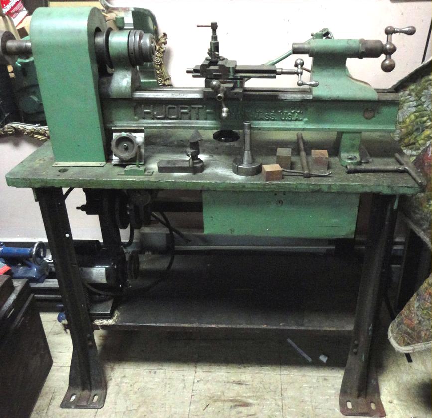
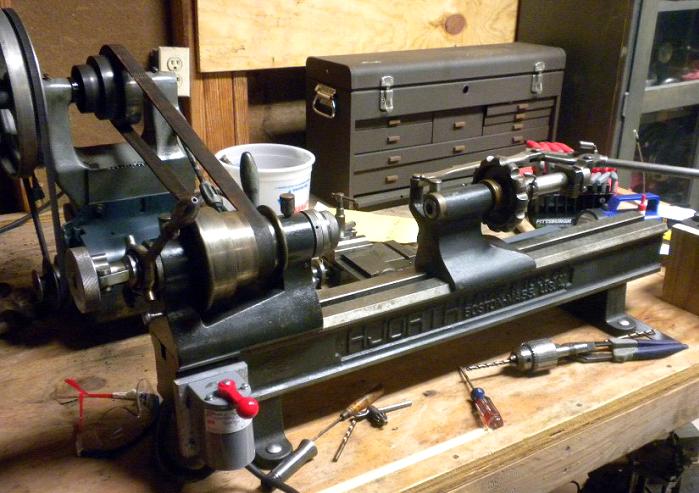
Mr. Henrick J. Hjorth had his Hjorth Lathe & Tool Company works at Woburn, Massachusetts in the USA (with the registered office at 27 School Street, Boston) and produced a range of what were known, in their day, as "Bench Lathes". However, today we have to add the word "Precision" to that description, if we are to understand the meaning of the phrase as understood in the late part of the nineteenth and early part of the twentieth centuries.
Pictured above, the screwcutting version of the lathe based was on a 1911 patent, was still available in much the same form in early 1930s. The capacity was 18" between centres and the swing 8
3/4"; the bed was 36" long and the machine weighed, with basic equipment, 143 lbs.
Spindle speeds depended upon the precise countershaft specified but were normally arranged to be 1000 rpm on top speed and 500 rpm on bottom. Whilst not shown on the lathe above, a backgear assembly was offered to reduce the speeds sufficiently for safe screwcutting which, on the Hjorth was transmitted to the top slide through a universal-joined shaft - a not uncommon method on early precision bench lathes.   As a small aid to user-convenience, the mounting plates beneath the lathe feet were slotted, to allow a modicum of adjustment for belt tensioning. The compound slide rest, with a 5
1/2" top movement and a 41/2" cross movement, was topped by an eccentric toolpost very similar to that found on Rivett lathes.
Both the headstock, with a 3/4" bore, and the tailstock were fitted with a Brown and Sharpe No. 6 taper, 2
1/2" long. One of the optional tailstocks was very unusual in being fitted with a combination screw and lever-feed actions; the screw feed had a maximum travel of 23/4" and the lever feed 41/4".
One unusual but most useful feature on the Hjorth was the use of separate mounting pads under each bed foot. These were fitted with screw adjusters, mounted at the rear, and allowed the lathe to be moved forwards slightly to compensate for belt stretch.
As was usual with this class of lathe, a host of other special accessories was available, including a remarkable bed-mounted combination vertical milling, gear-cutting and dividing attachment; some examples of these accessories can be seen on the accompanying pages..
Other makers of similar lathes in the USA included: Levin, Bottum, American Watch Tool Company, B.C.Ames, Bottum, Potter, Pratt & Whitney, Rivett, Wade, Waltham Machine Works, WadePratt & Whitney, Rivett, Cataract, Hardinge, Elgin, Remington, Sloan & Chace, and (though now very rare) Frederick Pearce, Van Norman, Ballou & Whitcombe, , Sawyer Watch Tool Co., Engineering Appliances and Fenn-Sadler the "Cosa Corporation of New York" and UND.

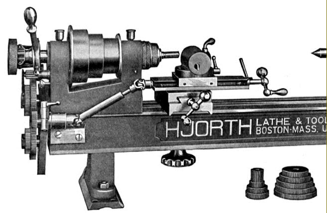
Although the Hjorth would normally have been supplied as a plain-turning lathe, with a simple tip-up tool rest, this comprehensive screwcutting attachment was produced to drive the top slide of the optional compound slide assembly.
The tumble reverse  (A) was driven by a gear (B) that slid onto the end of the headstock spindle. The tumble-reverse assembly, and its method of engagement with a gear formed on the inside of the largest diameter of the headstock cone pulley, bears an unmistakable likeness to that employed on the Rivett 8-inch Precision lathe - even to the thin, spring-steel engagement "lever".

Universal Milling Attachment.
Fitted with its own bed base plate that incorporated a compound slide, thjis unit could be used in the conventional way, to impart a vertical motion to the workpiece or, fitted with the dividing-gear bracket shown fastened to the end of the bed, made to cut racks. A simple dividing head and quill was also available, as shown below.

Component parts of the Milling Attachment.
(A) the Universal Attachment and bed mounting plate
(B) Angle Bracket and Swivel-base Vice; clamped to face of column slide
(C) Index plates
(D) Dividing Gear Bracket for Rack Cutting Attachment
(E) Dividing Head or Quill

The Standard Vertical Milling Attachment, carrying a pawl-operated indexing unit and shown here combined with the Universal Milling Attachment.

Hjorth Universal Grinding Attachment with screw-action cross feed and lever-action longitudinal feed.  The centre bracket could be removed and replaced with the Internal Grinding Attachment shown below.

Hjorth Internal 32,000 rpm Grinding Attachment. There were at least two different versions produced, one for use on lathes and another, almost identical, for use on plain or universal grinders. The variety illustrated had its own speed-increasing countershaft built on to the mounting bracket with the bearings supplied with oil from wick-feed lubricators.

An unusual patented combination tailstock with screw and lever feeds. The dividing head fastened to the barrel was designed to hold rings that could be indexed round and bored through their edges by a drill held in the headstock chuck. Another use was to sharpen small saw blades by replacing the drill with a grinding wheel. The collet capacity was 5/8" with step chucks available to hold up to 21/2" in diameter.

Lever-action tailstock with an adaptor to take full-size headstock collets

Lever-action tailstock with cross-feed slide.
Just visible at the end of the main casting is a dividing plate, designed to assist in off-set drilling, tapping and indexing. The drill was held in the headstock and the workpiece in the 3-jaw chuck on the end of the tailstock barrel.

Hjorth relieving attachment

Patented on  the 11th of April 1911, the Hjorth headstock was beautifully constructed from top-class materials

Original catalog description of the headstock's main components

Hjorth Headstock Spindle.
Like the bearings it ran in, the 3/4" bore main shaft was made from tool steel, hardened, ground and hand lapped. The chuck-mounting threads were finish ground after hardening and the front bearing was of the two-angle type, with tapers of 3 and 45 degrees. Both bearings were fitted with four felt oiling grooves. The spindle-locking device was rather unusual - a spring-loaded plunger being allowed to impinge against a serrated ring.

Section through the unusual Combination Screw and Lever-action tailstock

Unusually casual, or artistic catalog description of the Hjorth tailstock