 |
|
|
|
|
|
|
|
|
|
|
|
|
|
|
|
|
|
|
|
|
|
|
|
|
|
|
|
|
|
|
|
|
|
|
|
|
|
|
|
|
|
|
|
|
|
|
|
|
|
|
|
|
|
|
|
|
|
|
|
|
|
|
|
|
|
|
|
|
|
|
|
|
|
|
|
|
|
|
|
|
|
|
|
|
|
|
|
|
|
|
|
|
|
|
|
|
|
|
|
|
|
|
|
|
|
|
|
|
|
|
|
|
|
|
|
|
|
|
|
|
|
|
|
|
|
|
|
|
|
|
|
|
|
|
|
|
|
|
|
|
|
|
|
|
|
|
|
|
|
|
|
|
|
|
|
|
|
|
|
|
|
|
|
|
|
|
|
|
|
Hercus was a family-owned southern Australian machine-tool maker with works in Anderson Street, Southwark. Besides drills, hacksaws, shapers, tool & cutter and semi-universal grinding machines - and at least two models of horizontal miller (with a vertical attachment) - they manufactured, from the late 1920s onwards, a range of lathes aimed at the amateur, semi-professional market and education markets. Whilst their initial effort was a simple bar-bed lathe (followed, in the late 1930s by a clone of the English Portass) their best known and most successful lathe was a copy of the late 1930s American 9-inch South Bend "Workshop" lathe. The Hercus was then gradually modified and improved with production lasting until 2001 when the final model, the 260 Series, with a 10" swing and able to pass 26 mm (1") through the spindle bore, came off the production line. The later models, although somewhat disguised with "angular" styling, still had tailstocks and top slides with a charmingly original South Bend appearance. However, one significant difference, incorporated from the 1960s onwards, was to the screwcutting arrangements - changes that necessitated the use of new threading charts. Another alteration, to improve the machine's appeal to training and educational buyers, was to enclose the neatly built-on 16-speed countershaft unit, and the changewheels, to modern health-and-nanny standards.
It is interesting to note that the firm's founder, Mr. F.W. Hercus, wrote to the British press in 1954 (but without revealing who he was) and outlined Customs' requirements for immigrants who took their own model-engineering machine tools with them to Australia. He also pointed out that, whilst it took sixteen weeks' work in England to buy a Model C South Bend, in Australia an "equally good" copy could be bought with just ten weeks' wages. Fred Hercus was actively involved in model engineering and a member of the South Australian Society of Model and Experimental Engineers. He lived in the Adelaide foothills (his private 5" track is still visible from the New Norton Summit Road) and in the early years of the 21st century one of his 5" gauge locomotives (made by him personally) was still running regularly on Society open days. He also constructed, initially for his own use, a one-off horizontal milling machine that used components from his lathe in the spindle-drive arrangements. Successfully completed, the machine was to reach small-scale production,
Although most Hercus models followed the traditional 3-model South Bend line-up of a Model A (with power cross feed and screwcutting gearbox), Model B (with changewheels and power cross feed) and Model C with changewheels and hand cross feed, a Model D was also produced. According to a long-serving ex-employee this was constructed at the behest of the Australian educational establishment and had twin leadscrews and a power-feed apron with a positive instead of cone clutch - the arrangement causing several difficult-to-solve problems. If you have a model D Hercus the writer would be very interested in making contact. During the 1960s Hercus supplied South Bend in the USA with a large batch of Model A lathes; fitted with Camlock spindles they were painted cream - and so are easily recognised should you come across one.
Continued below:
|
|
|
|
|
|
|
|
 |
|
|
|
|
|
|
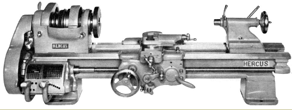
Early 9-inch Hercus Model A with screwcutting gearbox and power cross feed but bereft of any belt guarding. The operator is John Leask who worked at Hercus for almost fifty years.
Early Hercus 9-inch Lathes:
Virtually indistinguishable from the original American South Bend lathes, the first Hercus 9-inch copies were made in the same A, B and C models with, respectively, a gearbox and power feed, changewheels and power cross feed and changewheels with a hand-operated cross feed. However, as production settled down, both smaller and more significant changes began to creep in. By the early 1960s the option was being offered of a roller-bearing equipped headstock--a conversion that left little surrounding metal, but not to any apparent disadvantage in performance, whilst at the same time the fitting as standard of an 8-speed V-belt drive (in place of a flat-belt system), instead of making it optional as in the USA, was an obvious step to modernise the lathe and widen its appeal. The compound slide micrometer dials were increased in diameter from the inadequately-sized originals and, at some point in the 1950s, safety considerations caused the company to offer the option of comprehensive guarding of the motor-to-countershaft and countershaft-to-headstock belt runs - again, a specification long-available on the South Bend but only encouraged by the American company (in their advertising literature) for educational and instructional use.
Hercus offered two types of countershaft: a "vertical" version, the Type H, and a "horizontal" model, the Type P. Both H and P used an A-section 35" belt to drive the headstock pulley but the belt from motor to countershaft belt on the former was an A-section 42" and on the latter an A-section 31". Both countershafts were bolted to the back of the bed (so making the lathes self-contained and consequently easy to set up) and employed bearings held between bolts threaded through claws to give an adjustable "floating" housings, a design not unlike that employed for many years on American Atlas lathes - from which, no doubt, the inspiration came. The design allowed some freedom for the both the bearings to "float" into the correct position and for the top countershaft 4-step pulley to be lined up parallel to its mate on the headstock - a prerequisite for quiet running, extended belt life and efficient power transmission. The customer was given the option of ordering either plain bearings or a more expensive type of encapsulated deep-groove ball race that, as well as being freer running, would have had the advantage of allowing the assembly to tolerate even greater misalignment. The countershaft head incorporated a neat belt-tension adjustment system, operated by a single handwheel, with a quick-action lever-operated cam to slacken the belt to allow speed changes. Unlike the South Bend countershaft, where the over-centre belt tensioner-cum-adjuster was mounted on the right-hand leg of the countershaft and tended to skew the head to one side as pressure was applied, in the Hercus model the belt adjustment worked in a line through the middle of the pulley - this neat arrangement further helping to keep all the forces in line and so reduce bearing loads and pulley wear. Whilst some lathes had their motor was mounted on a separate hinged plate (that allowed belt tension adjustment to be made very easily) others had the motor bolted directly to the back of the countershaft with the resulting inconvenience of belt adjustment requiring the motor to be shuffled about on its mounting bolts.
Both single and double-step V-pulleys were offered for the motor to countershaft connection the latter a cheap and simple way of doubling the number of spindle speeds. Despite the new arrangements to keep fingers out of belts, the changewheel cover (in aluminium on some models instead of South Bend's cast iron) still did not have any means of being locked closed at the front and could be knocked open by the lightest touch from the hand - although a large T-headed screw was provided (instead of the tiny South Bend thumb type) to bear against the cover's pivot pin to stop the assembly from vibrating open.
The tailstock, still with a No. 2 Morse taper barrel, followed Boxford practice in being filled in over its front surface and (instead of the loose spanner previously required) fitted with a self-contained lever-operated cam that ran transversely through the casting from front to back.
Originally, as a form of stand, just a pair of plain cast-iron legs with a sheet-metal chip tray was offered but, at some point in the 1950s, neat cabinet bases became available; some had two separate plinths while others were of a more modern style with an enclosed back.
Photographs of the white Hercus below by Charlie Lear:
|
|
|
|
|
|
|
|
|
|
|
|
|
|
 |
|
|
|
|
|
|
Late Model Hercus Model ATM Series 260 belt-drive lathe with backgear; the multi-gear dial thread indicator fitted was of the type able to cope with a wide range of Metric thread pitches.
Two models were available: the Model A with a screwcutting gearbox and power cross feed and the Model B which retained the power cross feed, but had screwcutting with changewheels.
Running in taper roller bearings, with a bore of 11/16", the spindle had its nose threaded 13/4" 8 TPI and a No. 4 Morse taper. However, as an option, it was possible to specify a spindle bore of 1 3/8" with a D1-4" Camlock nose. 16 spindle speeds were available from 50 to 1680 RPM with a 0.5 h.p. 50 Hz motor, or 60 to 2000 RPM with a 60 HZ. Two bed lengths were produced (with or without flame hardening) that admitted either 21" or 30" between centres.
A 9-speed geared-head version of the lathe, built in two versions, was also manufactured (illustrated below) the Hercus 260G. A 0.75 h.p. motor on the back of the lathe drove the hardened gears in the headstock through a V-belt. The spindle specification was identical to the belt-drive machine with a speed range of 52 to 1600 RPM (50 Hz) or 62 to 1920 (60 Hz).
For instrument or toolroom work a version could be supplied which was aligned to better than half the normal accuracy limits (in other words, the best of a production batch).
While the January, 1967 Hercus price list had the ordinary AT and ATM models at A$3880, it listed the two Model 260 geared-head lathes at considerably more:
Model AG or AGM (metric version) with thread-dial indicator: A$4,450
Model DG or DGM with thread dial indicator: A$ 4,770..
|
|
|
|
|
|
|
|
 |
|
|
|
|
|
|
Hercus countershaft and screwcutting gearbox drive.
Note the balanced cast-iron pulley on the motor shaft - a pleasing touch. Interestingly, in a reflection of the original design, the tumble reverse lever was still held in place by a through-bolt, even though its function was no longer to hold the gears in mesh - this being accomplished by a proper spring-loaded indent mechanism.
|
|
|
|
|
|
|
|
|
|
|
 |
|
|
|
|
|
|
|
|
|
Hercus 260-G
What must have been an expensive-to-produce version with a geared headstock.
|
|
|
|
|
|
|
|
|
|
|
|
|
|
|
|
 |
|
|
|
|
|
|
|
|
|
Hercus 260-G
Spindle-speed speed selector elector mechanism
|
|
|
|
|
|
|
|
|
|
 |
|
|
|
|
|
An early attempt at a roller-bearing headstock this Model "AR" has a screwcutting gearbox and power cross feed . The Roller-bearing specification was available across the range and so, using the usual models designations, it was possible to have a "BR" with power cross feed model but no gearbox or a basic "RC" with hand-powered cross feed and screwcutting by changewheels.
|
|
|
|
|
|
|
|
 |
|
|
|
|
|
|
A restored 1950s Hercus Model ARM - metric screwcutting gearbox, power cross feed, cabinet base and the tall H-type "vertical" countershaft that used an A-section 35" belt to drive the headstock pulley and an A-section 42" from motor to countershaft. The new owner has also installed that increasingly popular modification, a 3-phase motor, powered from an inverter, to give infinitely-variable control of the spindle speed.
|
|
|
|
|
|
|
|
 |
|
|
|
|
|
|
Comprehensive guarding of the motor-to-countershaft and countershaft-to-headstock belt runs. With no need to remove it to change speeds the countershaft guard was held on two studs, the headstock cover however was arranged to hinge up.
|
|
|
|
|
|
|
|
|
|
|
|
|
|
|
|
|
 |
|
|
|
|
|
|
Roller-bearing headstock 9-inch with a horizontal countershaft (like the H-Type, bolted to the back of the bed) and labelled, confusingly, the Type P.
This version is fitted with the optional-extra guard kit.
|
|
|
|
|
|
|
|
|
|
|
 |
|
|
|
|
|
|
This Hercus has only the single-speed drive from motor to countershaft and, as a consequence, a total of only 8 speeds.
|
|
|
|
|
|
|
|
|
|
|
 |
|
|
|
|
|
|
The countershaft bearings were held between claws in adjustable, "floating" housings, not unlike those employed for many years on American Atlas lathes. On some lathes the bearings were plain (as above) whilst others used a type of encapsulated ball race that may have allowed the assembly to be aligned more easily - although details of these units are lacking. The countershaft head (both "H" and "P" types) also incorporated a neat belt-tension adjustment system, operated by a single rear-mounted handwheel , with a quick-action lever-operated cam to slacken the belt to allow speed changes
|
|
|
|
|
|
|
|
|
|
|
 |
|
|
|
|
|
|
Encapsulated ball-race countershaft bearing
|
|
|
|
|
|
|
|
|
|
|
|
|
|
|
|
|
 |
|
|
|
|
|
|
Later versions were modernised by fitting the tall, built-on-countershaft unit with a hinged motor plate. Spot the T-handle screw that pressed against the changewheel guard pivot pin to stop the cover vibrating
|
|
|
|
|
|
|
|
|
|
|
 |
|
|
|
|
|
|
|
|
|
Whilst later lathes had their motor mounted on a separate hinged plate (which allowed easy belt tension adjustment) early models, like the one left, had the motor bolted directly to the back of the countershaft with the resulting inconvenience of belt adjustment requiring the motor to be shuffled about on its mounting bolts.
|
|
|
|
|
|
|
|
|
|
 |
|
|
|
|
|
|
An early Hercus "Model C" with the distinctively tall all V-belt drive countershaft but a plain-bearing headstock, small-diameter feed-screw micrometer dials and the original simpler type of "hollowed-out" tailstock with a separate spanner required to tighten the camping nut.
|
|
|
|
|
|
|
|
 |
|
|
|
|
|
|
|
|
|
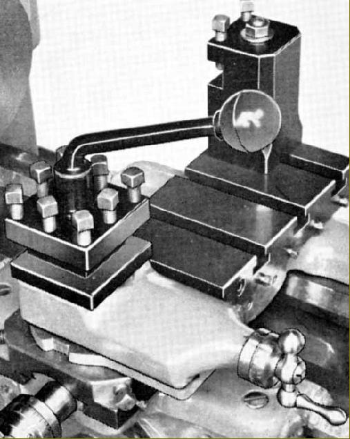
Optional T-slotted cross slide with a rear toolpost for parting off.
|
|
|
|
|
|
|
|
|
|
|
|
|
|
|
|
 |
|
|
|
|
|
|
|
|
|
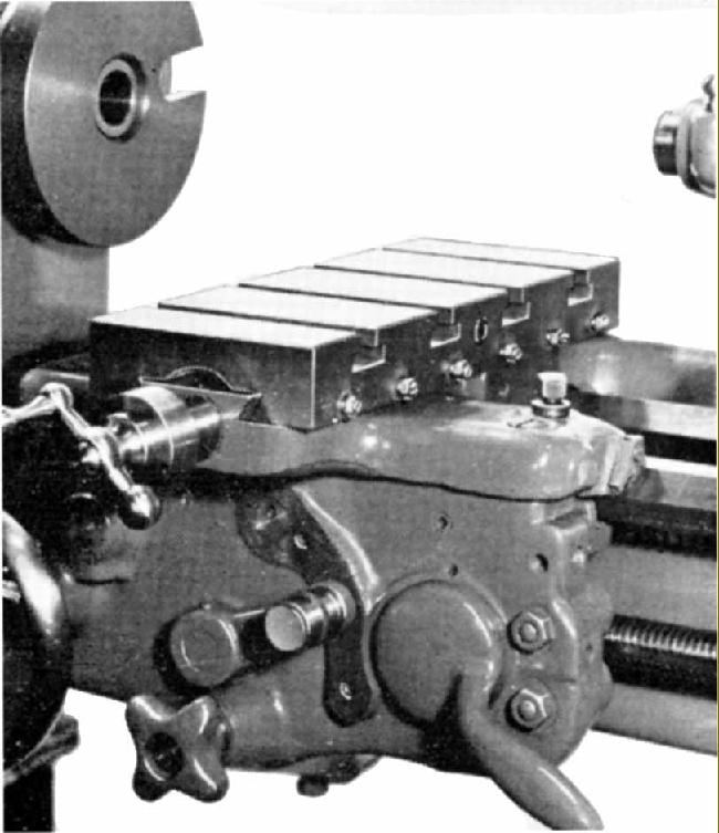
Optional boring table - to which the top slide could not be fitted. The Boxford version of this unit was rather more useful being just as long front to back but much wider.
|
|
|
|
|
|
|
|
|
|
 |
|
|
|
|
|
|
Standard plain cross slide. Both the cross slide and top slide feed-screw housings screwed into their respective castings - unlike the Boxford type that, in later versions, bolted on. The only significant difference between the Hercus and South Bend compound slides was the engraving of the swivel degree markings into the top face of the cross slide instead of around the edge of the top slide base.
|
|
|
|
|
|
|
|
|
|
|
 |
|
|
|
|
|
|
|
|
|
|
|
|
|
|
|
|
|
 |
|
|
|
|
|
|
|
|
|
Not all South Bend clones used the same fixing for the compound slide feed-screw carriers, but the screw-in ones on the Hercus (both cross and top slide) were unchanged from the original.
|
|
|
|
|
|
|
|
|
|
 |
|
|
|
|
|
|
Roller-bearing headstock: the large bearing-retaining plate and swollen headstock casting are evident in this picture of the tumble-reverse and changewheel assemblies.
|
|
|
|
|
|
|
|
|
|
|
 |
|
|
|
|
|
|
Four Hercus Model A lathes in what was described as a "manufacturing plant". However, it was posed in the Hercus plant during 1960 and shows, far right, long-term Hercus employee John Leask an three apprentices of whom the Company took on at least five every year
|
|
|
|
|
|
|
|
|
|
|
|
|
|
|
|
|
 |
|
|
|
|
|
|
View of the Hercus factory - probably in the 1930s - with 9-inch lathes in the fore and mid-ground ground and drills in the background
|
|
|
|
|
|
|
|
|
|
|
 |
|
|
|
|
|
|
|
|
|
Inspection sheet for a gearbox-equipped lathe signed by R.G.Excell, a Hercus employee who was a well-known model engineer and also qualified to act as a boiler inspector for amateur builders.
|
|
|
|
|
|
|
|
|
|
|
|
|
|
|
|
|
|