|
Home Machine Tool Archive Machine-tools Sale & Wanted Early Harrison L5 Lathes Page 2 Harrison Home Page |
|
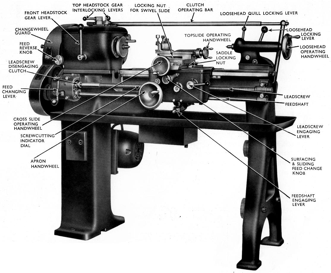
Shown on this page are examples of the early-type (1940s to early 1950s) Harrison L5 (for details of the full range and its development, click here). The first example pictured had a distinctly old-fashioned style of bed (the section beneath the gap swoops down to retain strength), and a plain-bearing headstock with a domed cover that reached down to the centreline of the bearings and, instead of being bolted in place, simply rested in a recess. Although this design of cover was necessary to allow the headstock bearing bolts to be undone, one might imagine that if oil instead of an oil-and-grease mixture was used for lubrication leaks would have been a serious problem. The clutch was operated by a long horizontal rod that ran the length of the bed and connected through a clevis pin on the headstock whilst sliding through a guide, supported on a tall bracket, at the tailstock end (although this fitting was not shown in all publicity pictures). |
|
The first L5, circa 1940-1945, had a distinctly old-fashioned pattern of bed (the section beneath the gap swoops down to retain strength), and a plain-bearing headstock with a domed headstock cover that reached right down to the centreline of the bearings. The clutch was operated by a long rod running the length of the bed at headstock level - a system that was used until around 1947. |
||
|
|
|
|
|
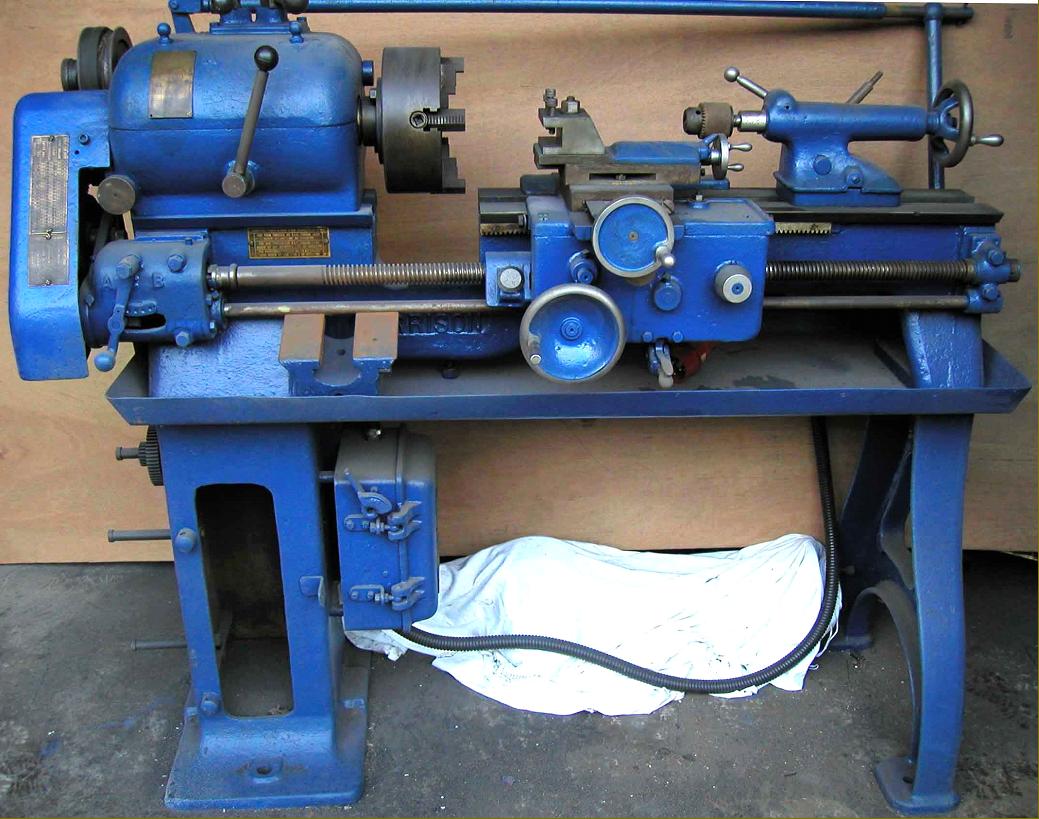
Second-generation (mid to late 1940s MK. 2 L5) with a deeper and stronger bed beneath the gap created by tripling the length of the headstock-end foot, a full cabinet stand fabricated from heavy-gauge sheet steel, a redesigned roller-bearing headstock carrying a shallower, bolt-on top cover and a short rod-type clutch lever. This version can be distinguished by its full-circle handwheels (without the micrometer marks), conventional zeroing micrometer dials and large combined belt and changewheel bolt-on cast-aluminium guard with curves on its forward-facing surface. |
||
L5 "Mk. 2" with a full screwcutting-gearbox. The leadscrew was only used for screwcutting and engaged by a simple, hand-operated, sliding dog-clutch at the gearbox end; the power shaft below the leadscrew was provided with a spring-loaded, safety over-ride mechanism to prevent damage in the case of a dig-in or other mechanical mayhem - on machines manufactured from the late 1950s this safety device was also offered as an option on the leadscrew drive - and recommended by the makers for use on machines intended for training workshops. The box offered a choice of 36 pitches and feeds from 4 to 60 t.p.i whilst a set of conversion gears (at extra cost) enabled the box to generate 15 metric threads from 0.5 mm to 7 mm pitch; the power feeds ranged from 0.002" to 0.065" sliding and 0.001" to 0.37" surfacing.
|
|
||
Early pattern "open" L5 3-speed screwcutting & feeds gearbox with downward-pointing cast selection lever. In this picture the sliding disengagement sleeve for the leadscrew - it's keyed to the reduced diameter of the shaft just before it enter the gearbox - can be clearly seen. Below it is the housing for the spring-loaded over-ride clutch that protected the changewheel drive train from damage when the power feeds were being used.
The standard set of changewheels supplied with the 9-inch lathe provided 26 threads from 2.5 to 40 t.p.i (with the option of a 120t wheel to give an additional 7 threads up to 80 t.p.i) whilst those with the standard 11-inch lathe enabled 33 threads from 2.5 to 80 t.p.i. to be generated. The gearbox allowed a very simple non-compound gear train to be used even for fine feeds.
|
|
||
|
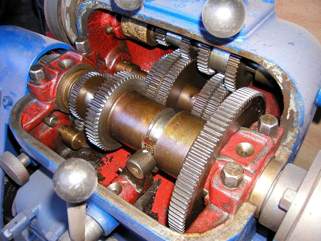
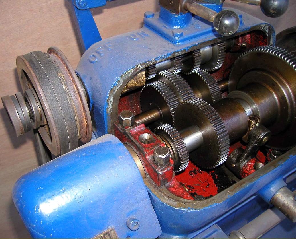
The headstock, always fitted with a clutch and combined friction brake (which mades operation by a single-phase motor much easier and more reliable) had a range of eight spindle speeds. Although the picture above shows a later L5/L5A headstock with the stiffer casting and "safety" high/low-speed lever, the arrangement of the gears within models from the early 1950s was identical. |
|
Very early plain-bearing L5 from around 1944 showing the first type of plain-bearing headstock. To allow access to the spindle bolts the front quadrant of the headstock was completely cut away and the domed-shaped headstock cover (that reached right down to the centreline of the bearings) simply rested in its recess instead of being bolted down |
||
|
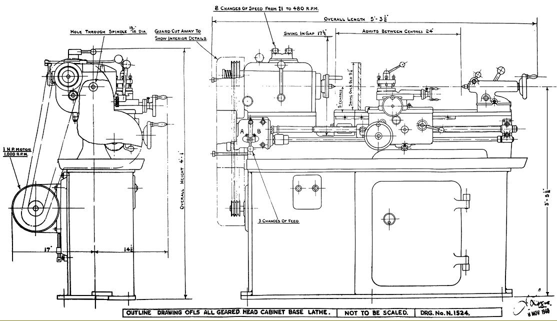
The spindle ran on a pair of pre-loaded, opposed Timken taper roller bearings at the front and a single-row ball bearing at the rear; the main double gear which slid along the spindle was cut from a single forging and slid on a seven-splines - the complete assembly being dynamically balanced. The gears were all hobbed from the solid, shaved, induction hardened and honed to produce the correct tooth form. The bore through the spindle of the original L5 was a little tight at 0.9125", but when the larger L5A lathe (11-inch swing) was introduced its spindle, with a 1.375" hole, was offered an option on the smaller machine - but I yet to find one so fitted. Besides the two sizes of screwed spindle the American L00 (L zero zero) taper nose was offered as an option and always featured the larger-bore hole. |
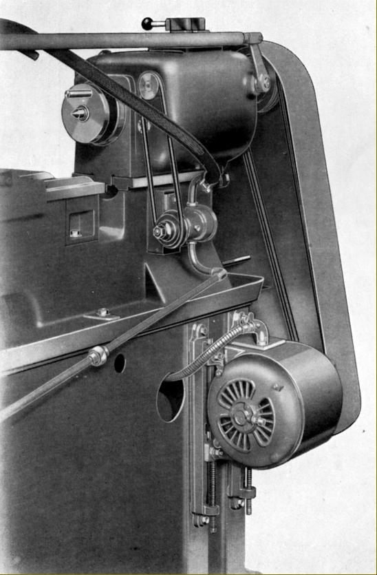
To drive the coolant (suds) pump a round-belt drive was taken from an extension of the headstock layshaft to a gear pump bolted to the back of the bed; if the assembly has survived - and it has often been replaced by a more effective electric pump - it is not unusual to find the sheet-metal guard missing.
The main motor was mounted on vertical rails, which allowed the belt tension to be quickly and easily set; on some later versions the rails were adjustable sideways, making a change of motor type and size a very simple operation.
On this model the clutch-operating arm projected backwards through the headstock casting and was usually connected to a full-length bar pivoted on a bracket at the tailstock end of the bed. On later models the clutch shaft rose vertically through the headstock casting and was connected to a headstock mounted lever.
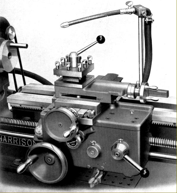
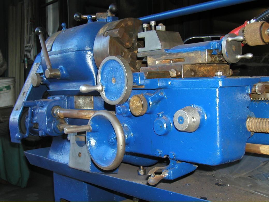
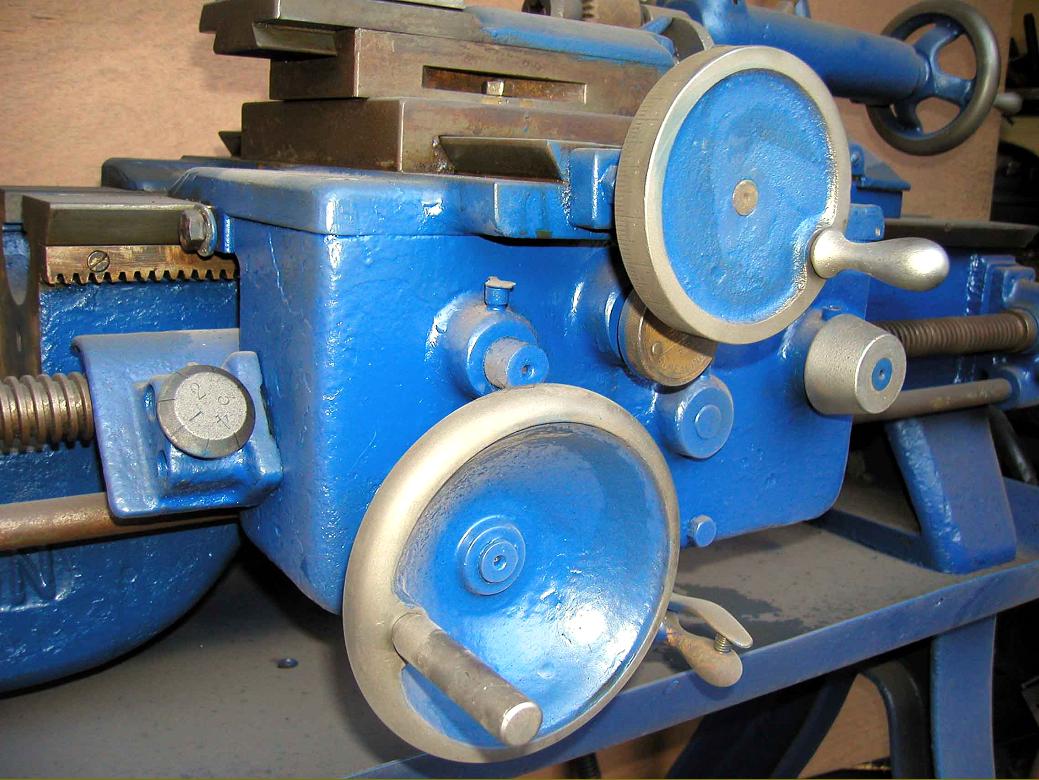
Late 1940s to early 1950s L5 carriage - distinguished, amongst other things, by the large-diameter cross-feed handwheel (without the micrometer graduations of the first models), the Harrison name cast into the front surface of the bed and the spring-trigger, made of bronze, on the power-feed engagement lever. In this picture the round-belt drive to the suds pump is visible.
The doubled-walled apron on all model of the L5 employed a push/pull button to select either power sliding or surfacing whist the power feed engagement lever, below the centre of the apron, was spring loaded and could be snapped into and out of engagement even under full load; the design was so simple, effective and easy to use that it was adopted across the entire Harrison range.
On all models both the top and cross slides were fitted with proper taper gib strips - instead of the cheaper screw-adjustment kind often found on small industrial lathes machines of this age - and the zeroing micrometer dials whilst not big enough, were nonetheless of adequate dimensions for younger eyes. A "clog-heel" toolpost was fitted as standard but both a 4-way toolpost and, later, a quickset toolholder, were on the options' list; the 4-way toolpost had a clamping bar with a rather-too-small white plastic ball on its end - and it is surprising just how many of these palm-hurting devices have survived unmodified when for a few pence something more comfortable could have been fitted. Unfortunately the cross slide was not, as on the later M Type lathes, of the full-length type; instead a short slide was used with tin inserts (that are frequently damaged on used machines) set above the cross-feed screw at the front and rear to protect it from the wearing effects of swarf. Later models retained the tin sheet at the front but were given a more elegant and robust cast aluminium cover at the rear. In the picture above the long tongue of the rear cover can be seen projecting backwards beyond the back of the saddle. Because the centre height of the original L5 was only 4.5-inches and the machine very heavily built, it was not possible to get sufficient depth in the top slide for a T-slot to be machined. Consequently the toolpost, single or 4-way, was secured by a stud (as in the picture above). When the 5.5-inch centre height L5A was introduced the saddle and cross-slide castings remained unchanged but the thickness of the top slide was increased sufficiently to bring the tool deck up to the right height and allow a T slot be cut - a modification that allowed toolposts and other fittings to be slipped in position much more rapidly. The full circle, solid handwheels would have delighted today's Heath & Safety fanatics..
|
|
|
Doubled-walled, the apron on all models of the L5 employed a push/pull button to select either power sliding or surfacing while the power feed engagement lever, below the centre of the apron, was spring loaded and could be snapped into and out of engagement even under full load; the design was so simple, effective and easy to use that it was adopted across the entire Harrison range. |
|
Home Machine Tool Archive Machine-tools Sale & Wanted |