|
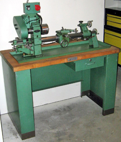
Manufactured by the Machine Tool Division of Hamilton Associates Inc. in their own factory at 1716 Whitehead Road, Meadows Industrial Park, Baltimore, Maryland 21207, the Hamilton Lathe/Miller combination was sold from mid-1960s onwards. Using the milling elements of this machine, the Company also went on to offer a pair of miniature, stand-alone vertical and horizontal milling machines.
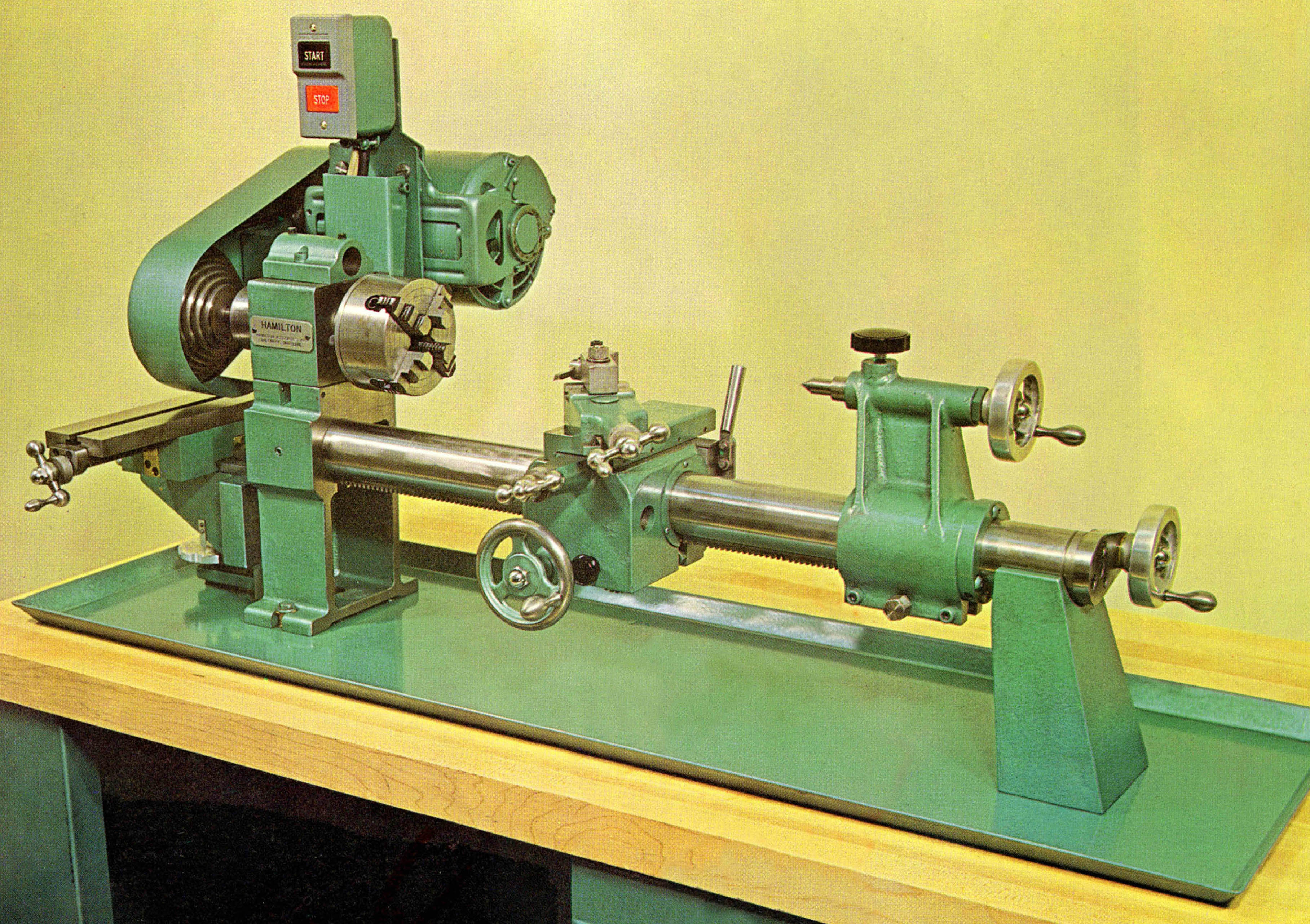
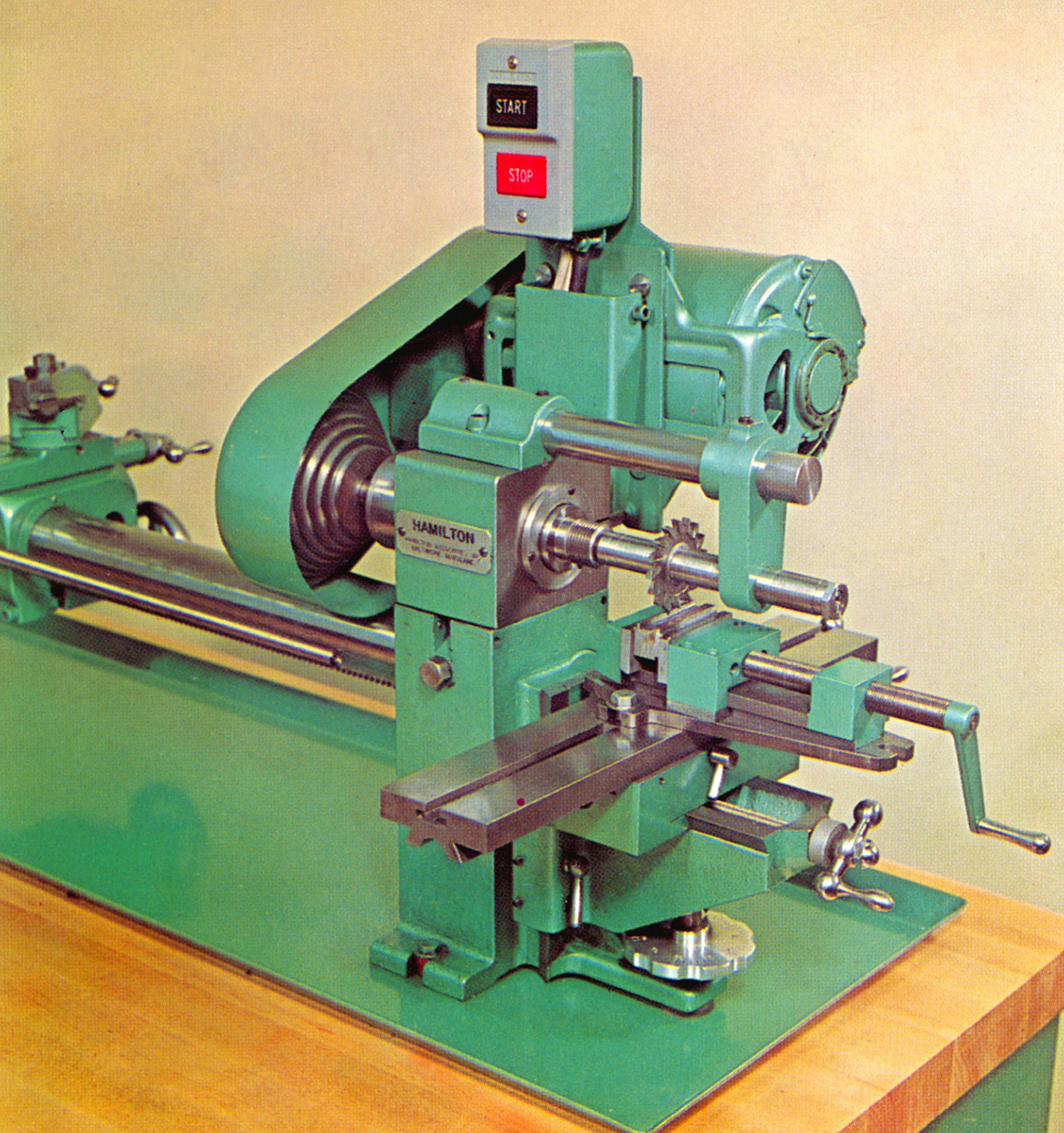
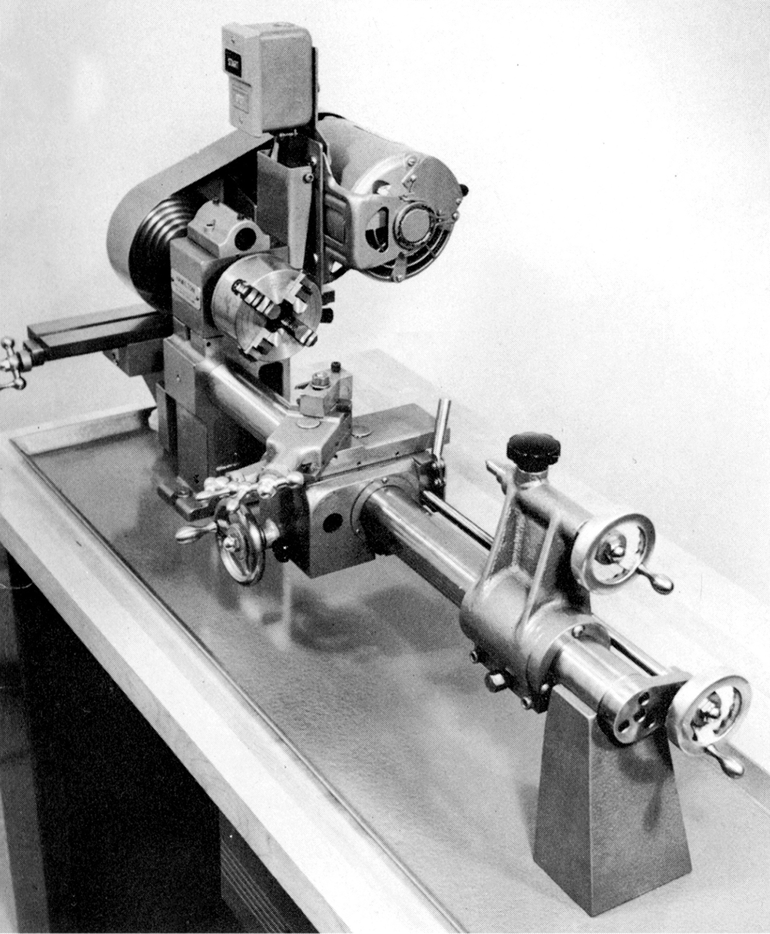
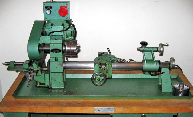
The concept of a combined lathe and horizontal miller had been tried as early as the latter part of the 1800s, when several of the high-quality American Bench Lathes - Stark and Cataract amongst them - had been offered with a horizontal milling attachment built onto the left-hand end of their beds. However, the combination of a round-bed lathe and miller might well be unique - and Hamilton broke further ground in having a headstock constructed in two parts so that the whole of the upper section, complete with spindle assembly and direct-drive resilient-mount motor, could be disengaged from the base section and swung through 180 degrees. Once positioned over the permanently-mounted milling table the 3/8-inch bore, No. 1 Morse taper spindle was fitted with a horizontal milling arbor and its support - a round overarm - secured within a simple casting fastened (by only two bolts) to a flat surface machined on the top face of the headstock. The machine was of limited capacity: a 6-inch swing (3-inch centre height) and 15-inches between centres meant that only smaller work could be attempted and that inescapable problem with a round-bed lathe, the lack of a gap, meant that the owner's ambitions were further thwarted.
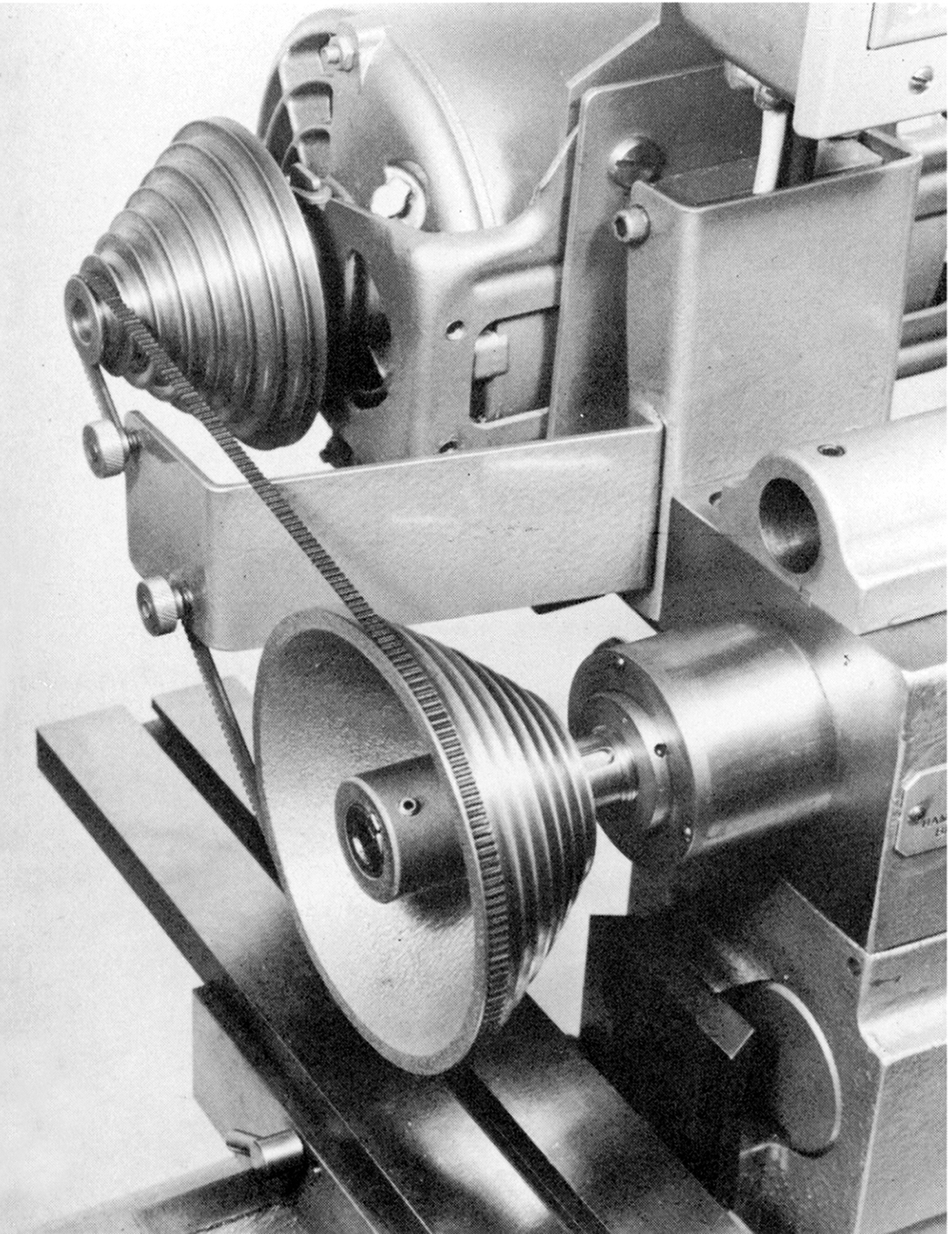
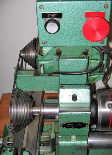
Driven directly by a rear-mounted 1/3 hp motor the overhung spindle pulley was fitted (like the Myford 254 lathe of later years) with a narrow "Gates-type" belt--the aim being to get as many speeds as possible into a confined space, yet without imposing too great a load on the bearings. As a result eight speeds, from 360 to 2820 rpm were available - though, as non passed through a backgear, torque on the lowest few would have been very limited and as a consequence heavy-duty milling all but impossible.
Heavily built, the carriage could be propelled along the bed by either a rack (working through a train of reduction gears from the handwheel) or, optionally, by a hand-turned, fine-feed leadscrew assembly which operated through a clasp nut on the back of the carriage; there was no method of connecting a power feed or screwcutting to the carriage but a simple type of "chase" screwcutting arrangement (again, echoing long-established precision lathe practice) was available on the options' list.
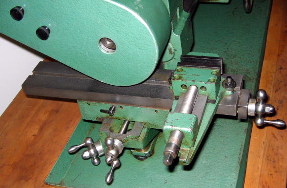
Although of simple construction the compound slide rest appears to have been well designed with extended end brackets to carry the feed screws - by which means they were afforded a great length of travel - and a cross slide which was of the full-length, evenly-wearing type.
With only an inadequate No. 1 Morse taper and the tailstock barrel was locked by a crude and cheap arrangement (of the type usually found on inexpensive wood lathes) where a plastic-handled screw acted directly against its external surface. Two designs of tailstock were fitted: the first had a vertical face at the front, the design limiting the reach of the barrel when the unit was brought up hard against the carriage while the latter was as far to the left as possible. In other words, it would have been impossible for headstock and tailstock centres to meet. Its replacement had the casting redesigned so that the front face curved forwards at the top, so allowing the centres to either touch or to be brought so close together that very short jobs could be turned between them.
For horizontal milling, a single T-slot 14" x 2.75" table with modestly-effective movements of 8 inches, 3 inches and 4.5 inches in longitudinal, traverse and vertical directions respectively was provided. On early machines, the elevation of the table was by a simple and inexpensive arrangement of a handwheel surrounding the lift screw; on later models this was replaced by a much more convenient and conventional screw-feed control working through bevel gears.
Despite the limitations inherent in its design, the Hamilton was an ingeniously conceived and executed machine and aimed at the school and training markets rather than the home workshop buyer - though its versatility and compact dimensions would certainly make one an attractive acquisition for anybody with limited space.
In 1966 the lathe sold for $592 with a faceplate, two centres, a compound slide rest, two motor pulleys (but no motor) a belt guard, chip pan and wrench. When equipped for work with a motor and General Electric switch, a 3-jaw chuck and backplate - and the essential fine-feed attachment - the cost rose to $733. The machine was 38.5 inches long, 17 inches wide and 21 inches high and, when complete with motor and switchgear, weighed approximately 150 lbs (68 kg)..
|
|