|
Home Machine Tool Archive Machine-tools for Sale & Wanted Flexispeed - Meteor - Simat 101 Lathes Flexispeed Meteor Simat Home Page Flexispeed Meteor Simat Page 2 Flexispeed Milling Machine Flexispeed Meteor 11 Flexispeed Shaper including handbooks and drawings, is available |
||
|
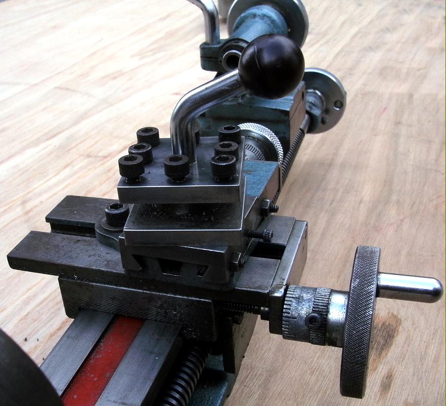
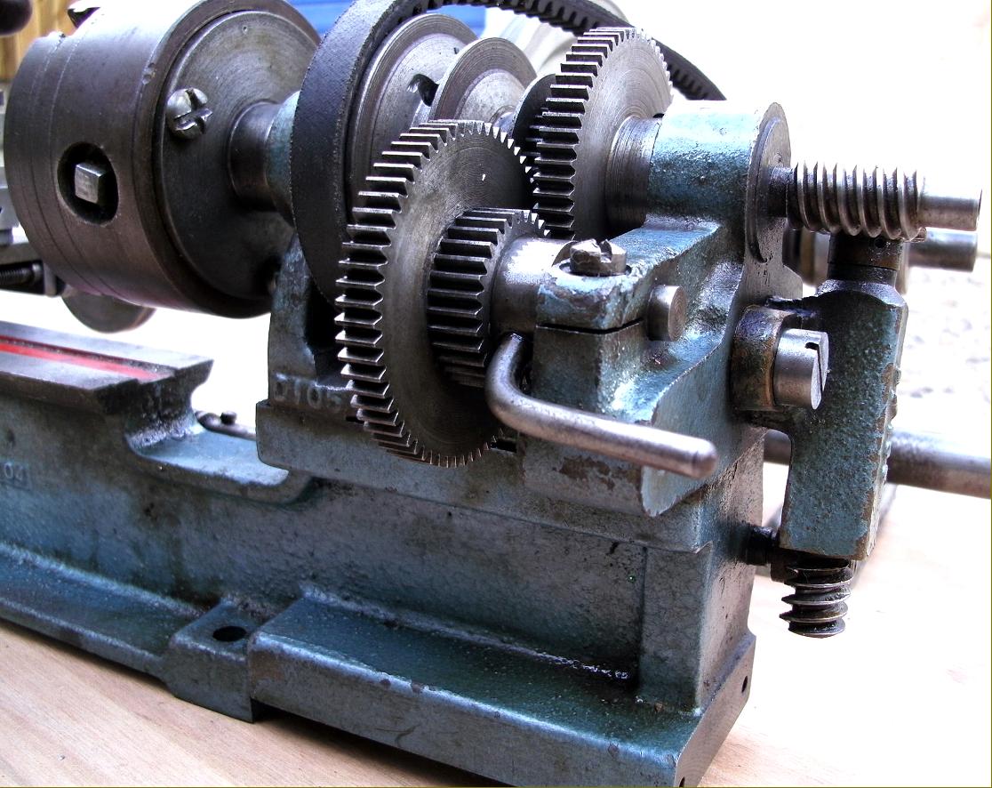
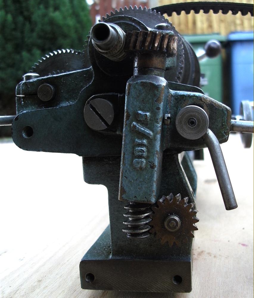
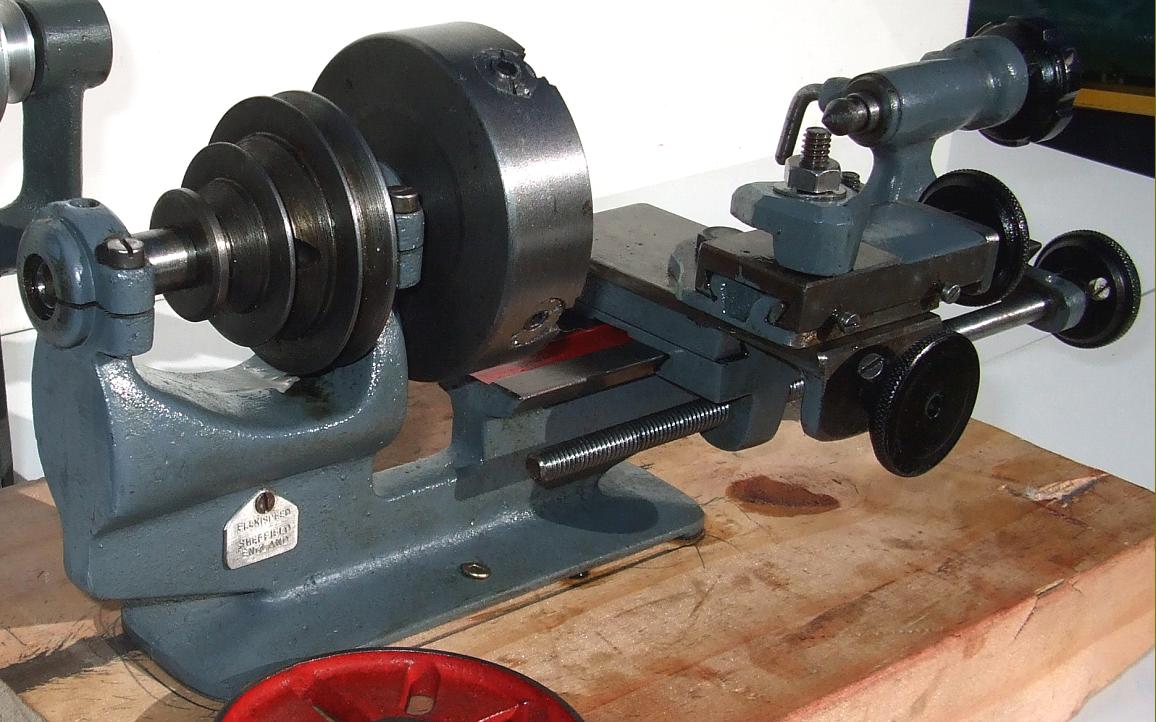
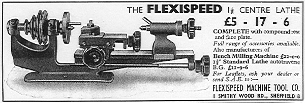
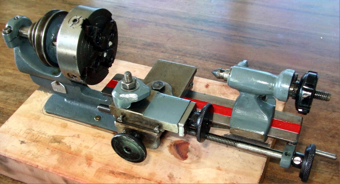
A short-lived version of a new basic Flexispeed, the "Student" introduced during 1954 at £5 : 17s : 6d. This model, intended to compete against the ever-popular and very cheap "Super Adept" reverted to the original 15/8" centre height but was fitted with a proper compound slide rest and a 3-step headstock pulley. Unrelated to the established types in the range almost every detail of its construction differed. A very smooth bed casting was used, without the usual edge ribbing, secured to the bench just two hold-down bolts at the headstock end. The tailstock, unlike that on all other Flexispeed types, could not be set-over to turn tapers. |
|
including handbooks and drawings, is available Flexispeed Milling Machine Flexispeed Meteor 11 Flexispeed Shaper Flexispeed - Meteor - Simat 101 Lathes Home Machine Tool Archive Machine-tools for Sale & Wanted |
||