|
One of only a handful ofmilling machines branded as Edgwick it appears that, from the 1920s onwards, all machine tools so branded - including the popular Mk.1 and Mk.2 lathes - were sold through the giant Herbert machine tool group.
The miller was also badged in post-WW2 years as the Archdale No.2 (this version continued to be manufactured until the early 1970s) as well as being almost identical to the Cuncliffe & Croom No. 2, this version also being marketed through Herbert. A clue as to what might have been going on can be had from a statement by Herbert that this miller was "Built for us by a "respected British machine tool company" i.e. in all likelihood by the Manchester-based firm of Cunliffe & Croom
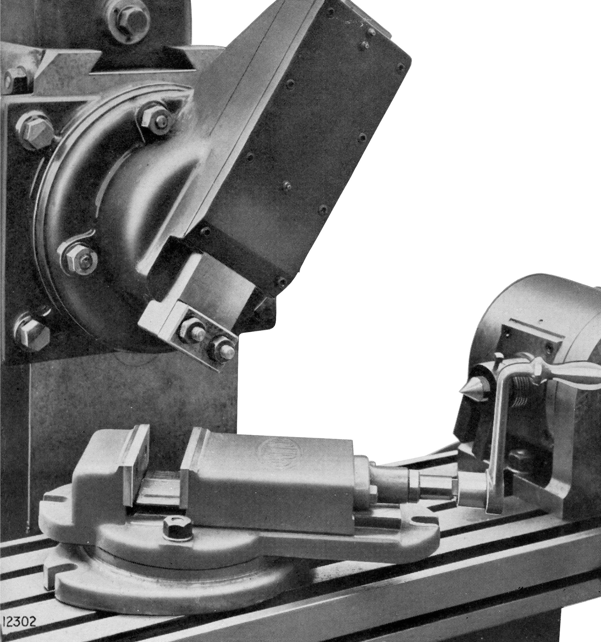
Intended for series professional use, two versions of the Edgwick were listed; a "Universal" where the 46" x 11" table was able to be swung 47° to each side of central and a model listed as the "Plain", this having a 40" x 10.25" (or later 42" x 10.375") but not of the kind that could be swivelled
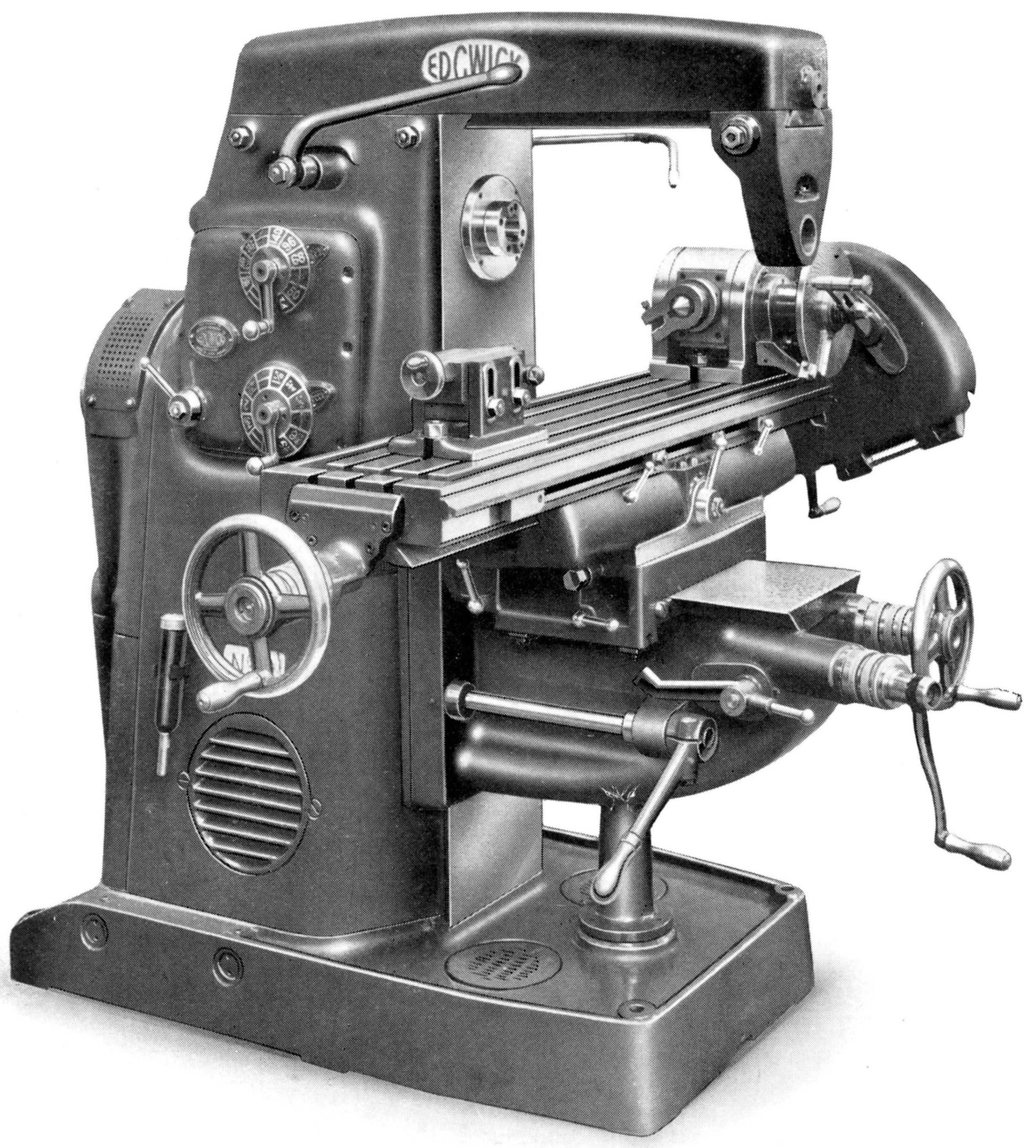
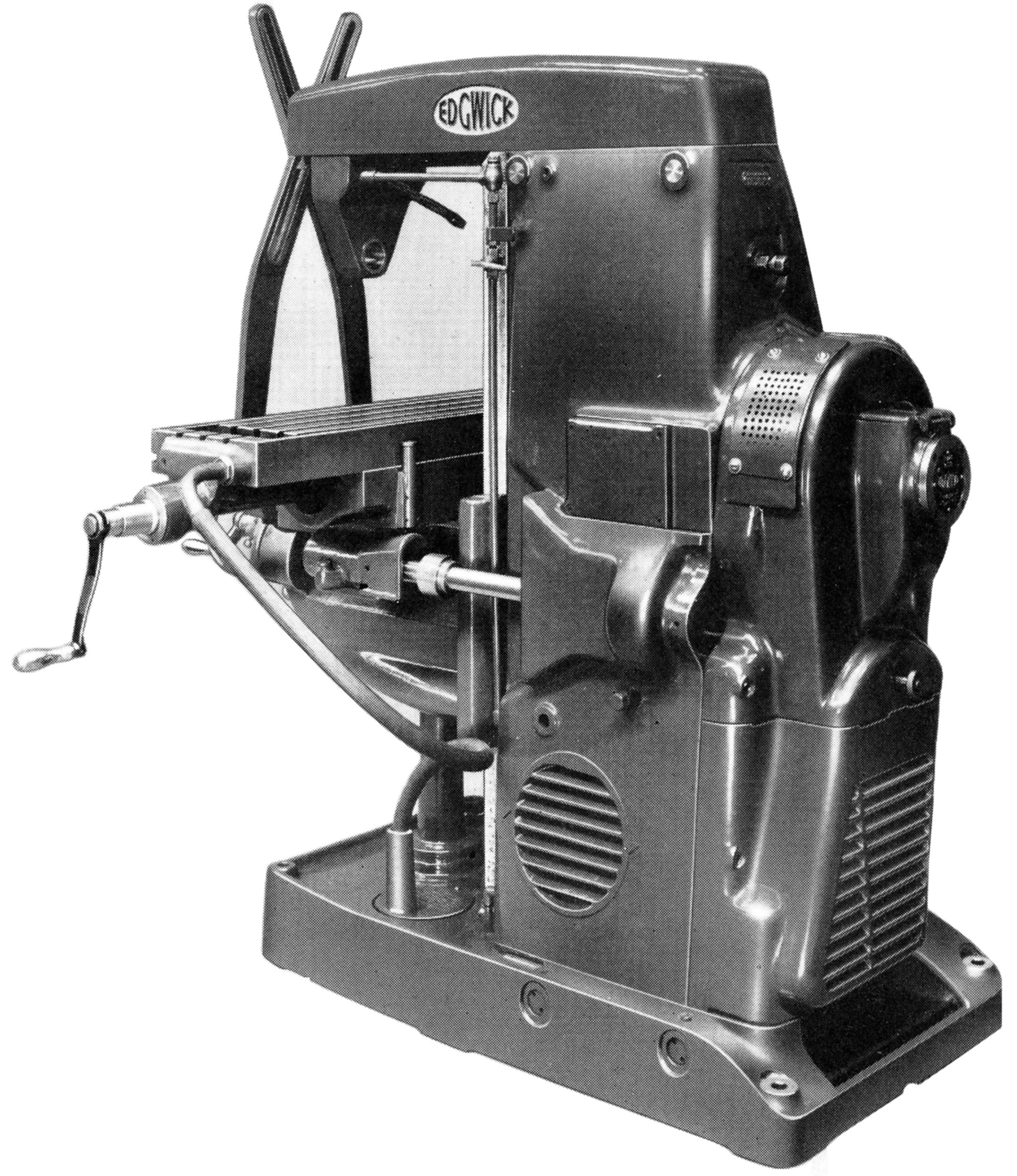
Edgwick Universal Milling Machine No.2
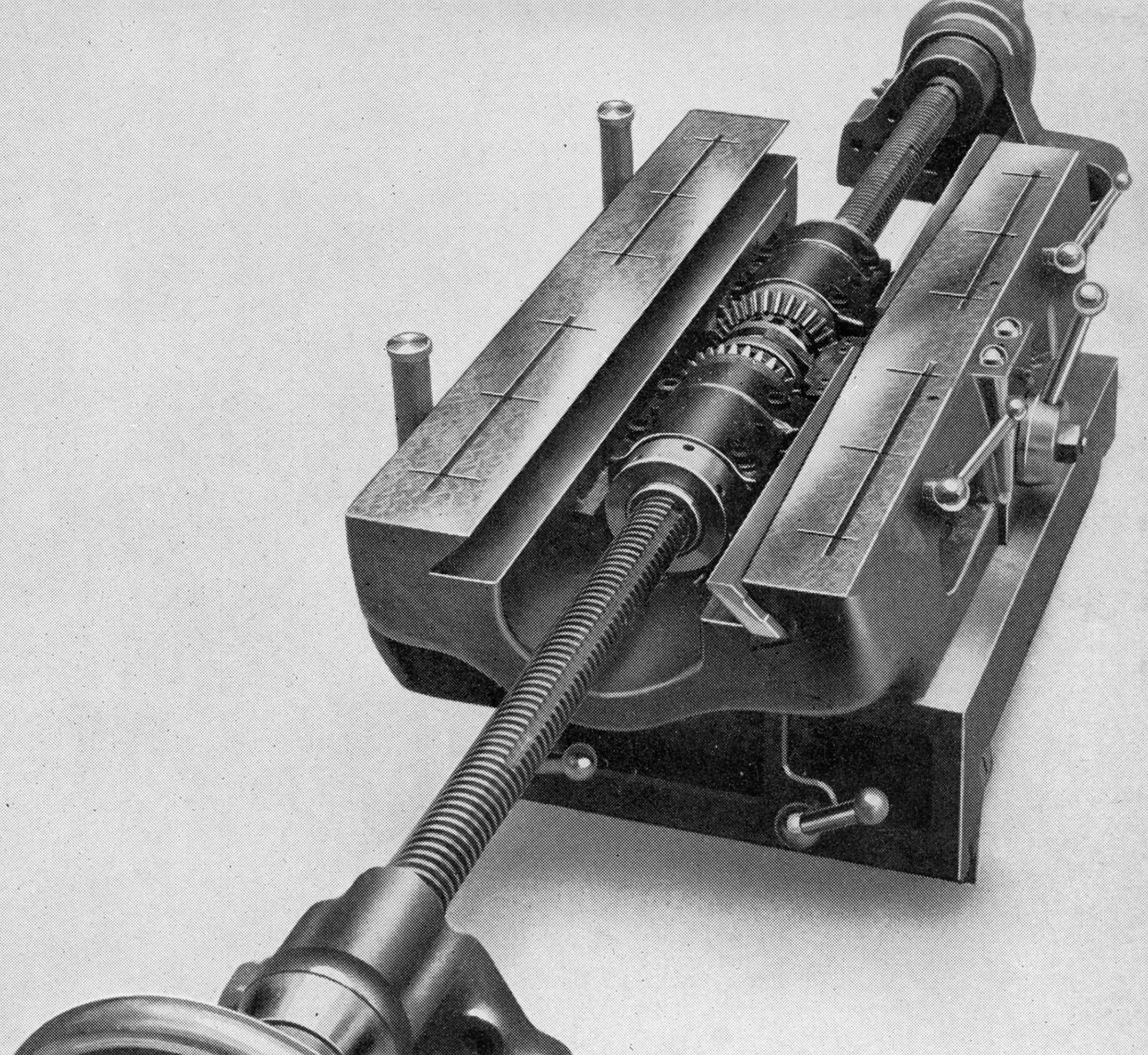
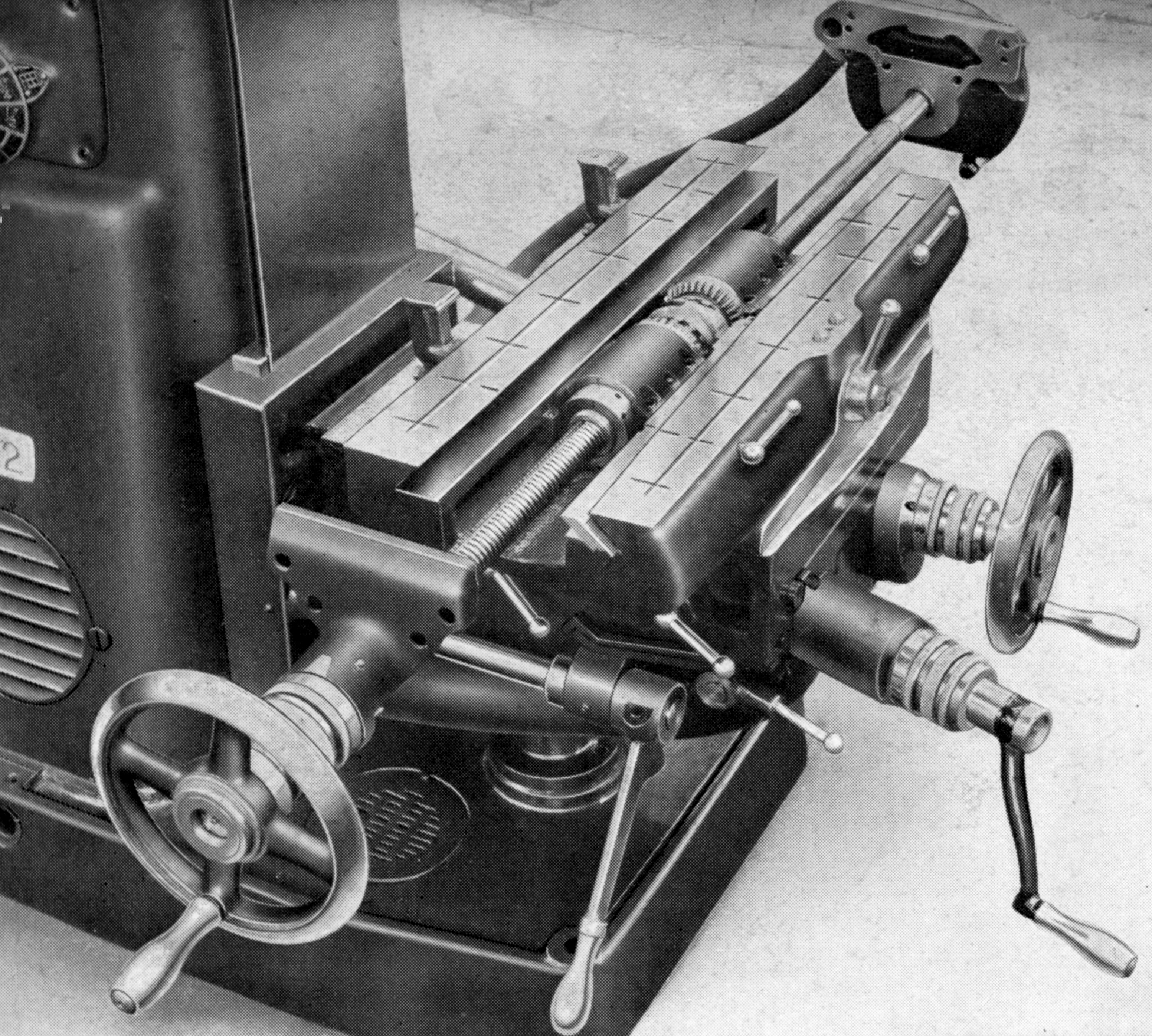
The table of the Universal had power feeds longitudinally of 25", in traverse of 8.25" (though reduced to 7.5" with the cross-bracing bars in place) and vertically, by hand only, of 17". The longitudinal feed screw ran through double compensating and adjustable nuts - and twin-opposed tapered gib strips were fitted that allowed the table to saddle clearances to be set accurately. Handles were spring-loaded - and so automatically disengaged when power feeds were in action - and both inch and metric calibration were available for the micrometer dials.
Power to the table came from a splined Carden shaft driven from a pulley mounted on the right-hand face of the column and turned by from an extension to the main spindle. Nine rates of table feed were provided that spanned 0.5" to 9.25" per minute.
The Universal, like all its type, was intended to mount a dividing head driven by a set of changewheels from the table's feed screw and so able to generate spirals and other forms.
The stout, internally ribbed cast-iron column and coolant-holding foot were cast as one piece and the overarm a modern type with a rigid, dovetail fitting to the main column.
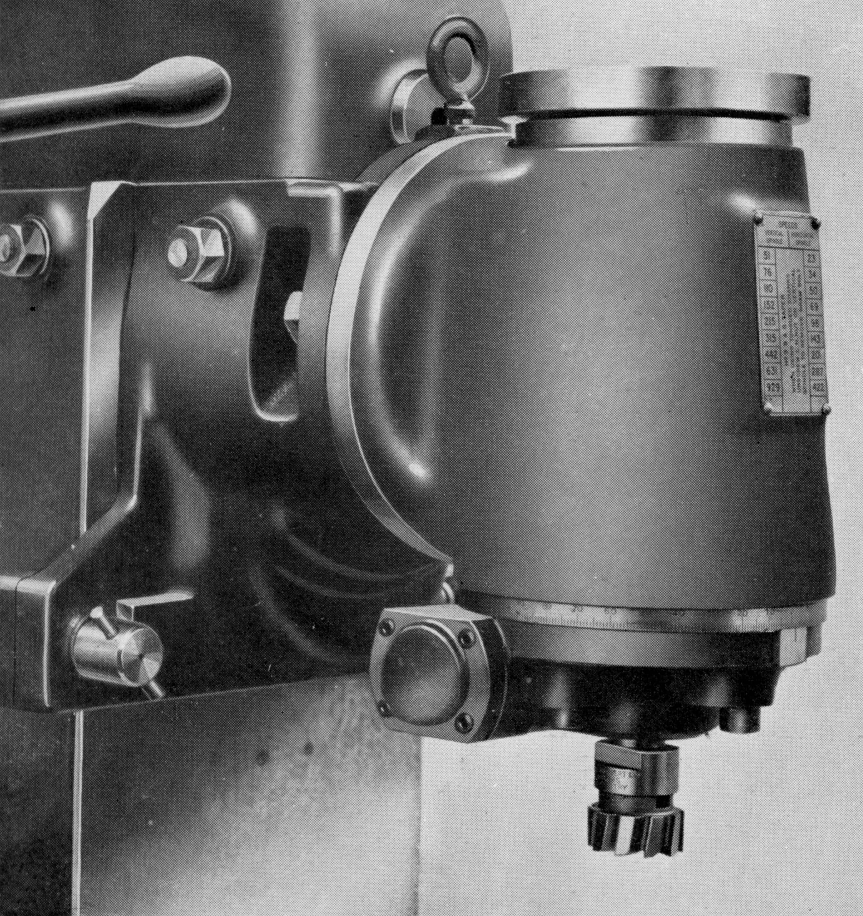
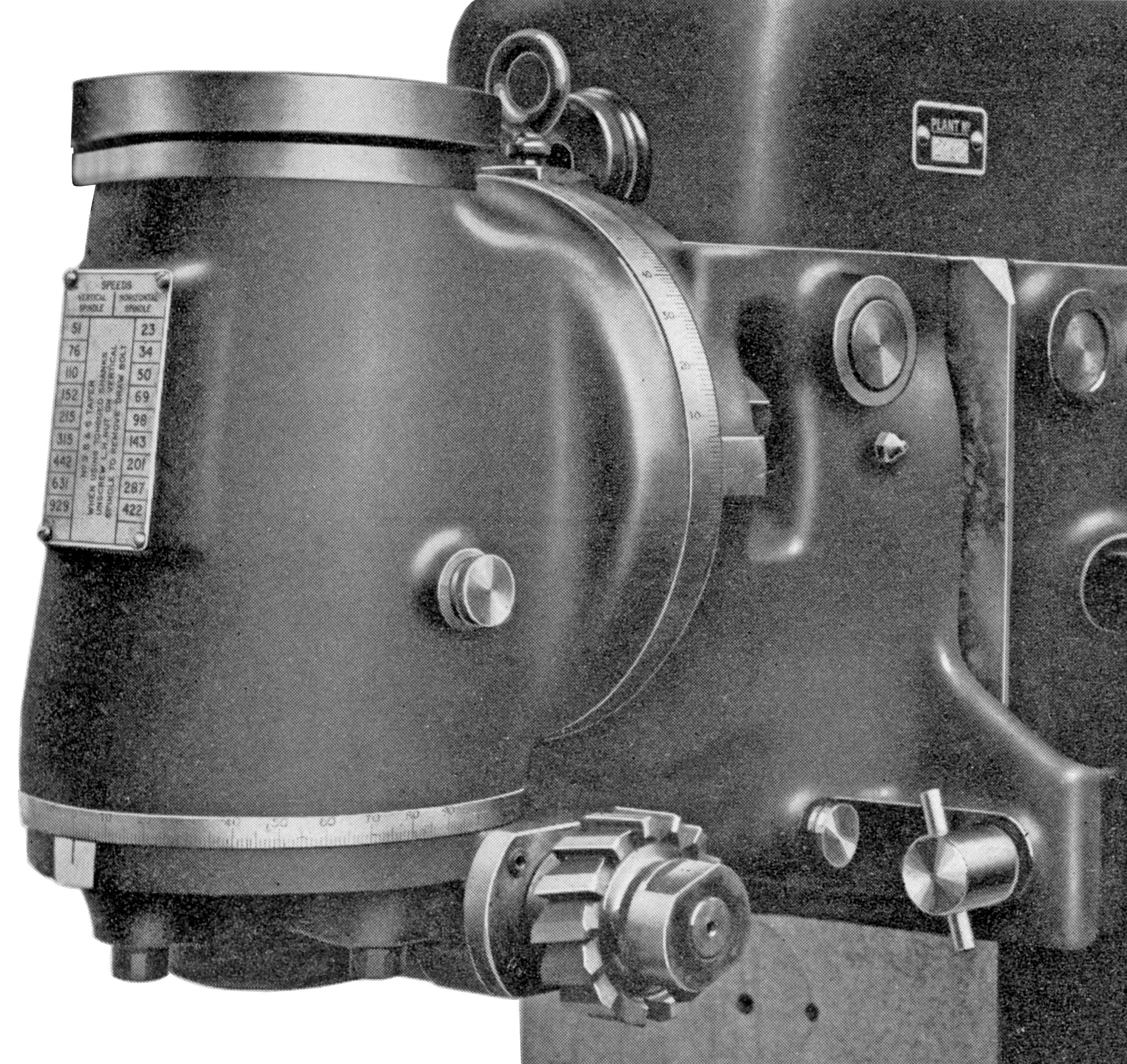
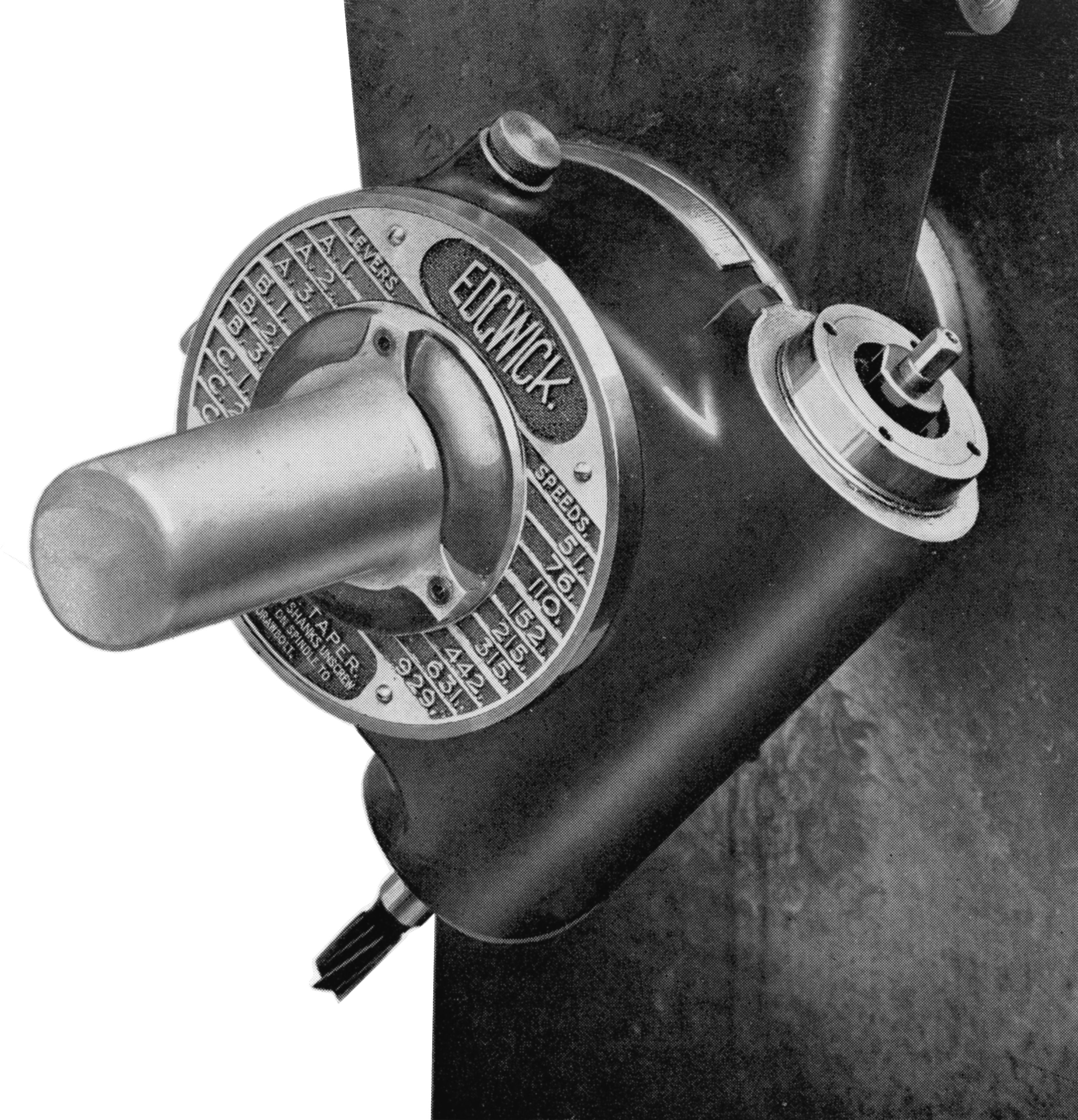
Made from nickel-chrome steel, case hardened at each end and running in high-precision taper roller bearings, the spindle was supplied as standard with a B.S.I. 1.75" taper with a removable key Nine speeds were available from 24 to 405 r.p.m., the drive coming via a 3-inch wide leather belt from a 3-phase, 3 h.p., 1425 r.p.m motor held within the main column. The maximum distance from the face of the column with the arm braces fitted was 22 inches (in effect the widest job that could be mounted) and the height from the floor to the centre of the spindle 46.75 inches.
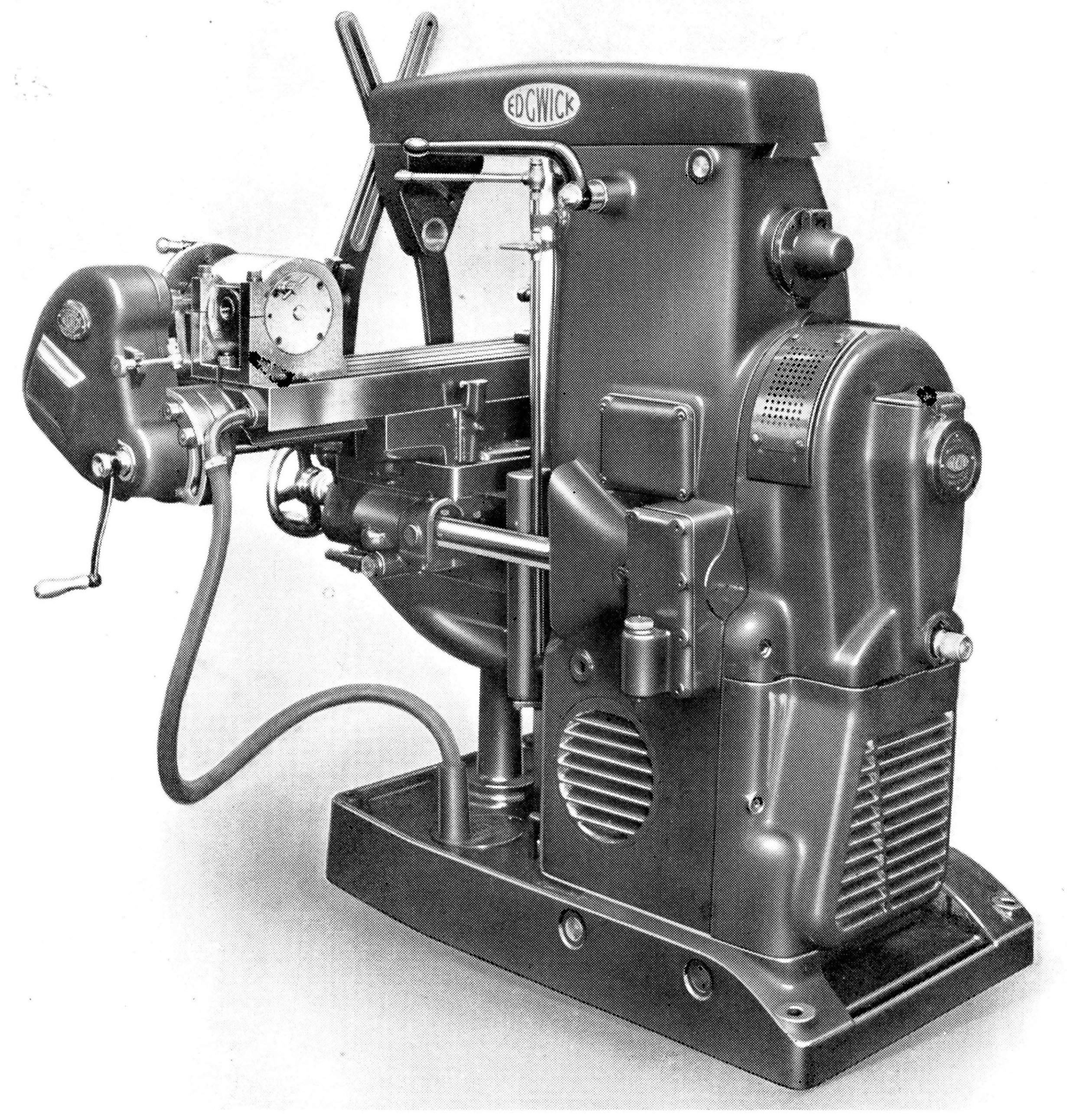
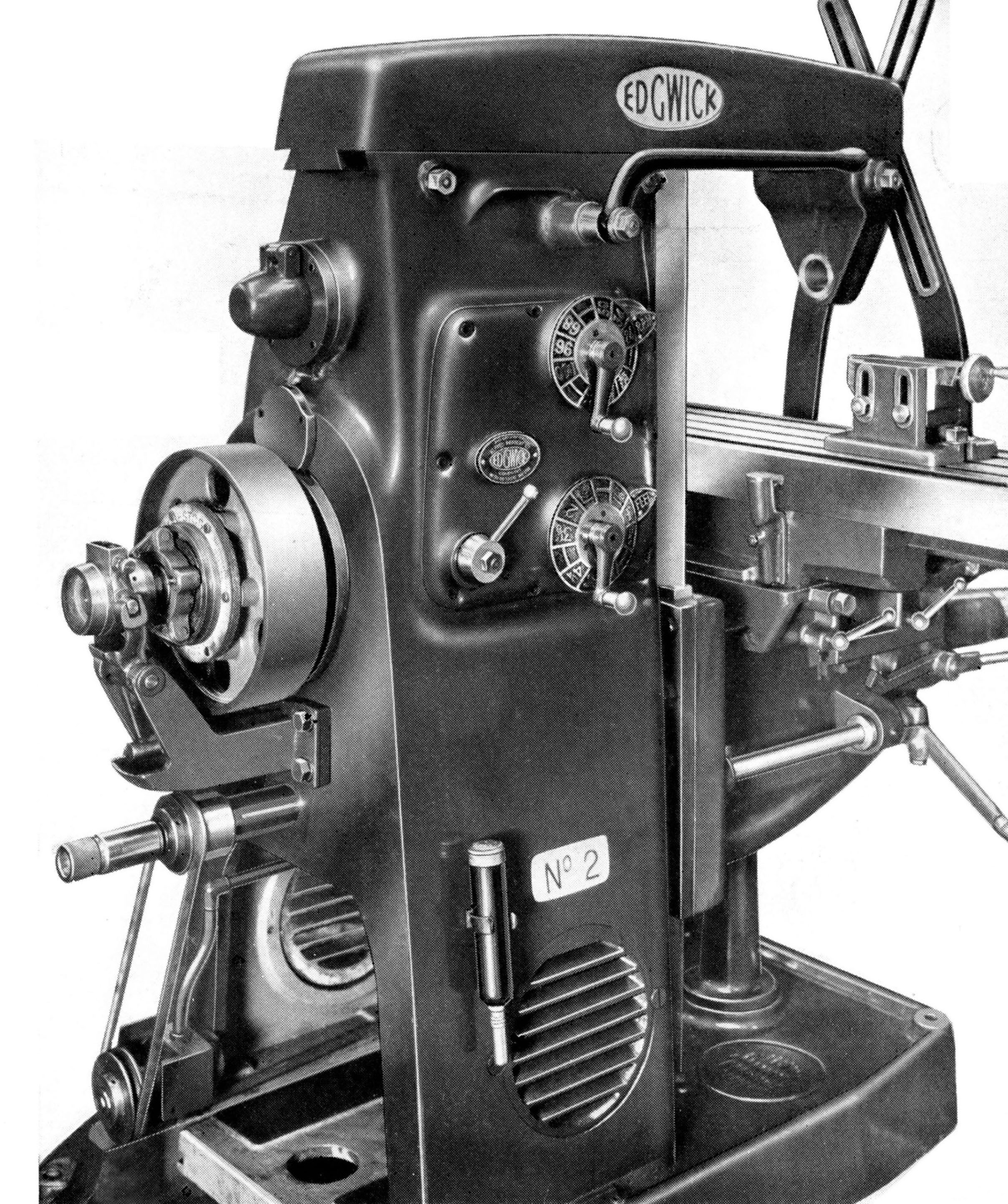
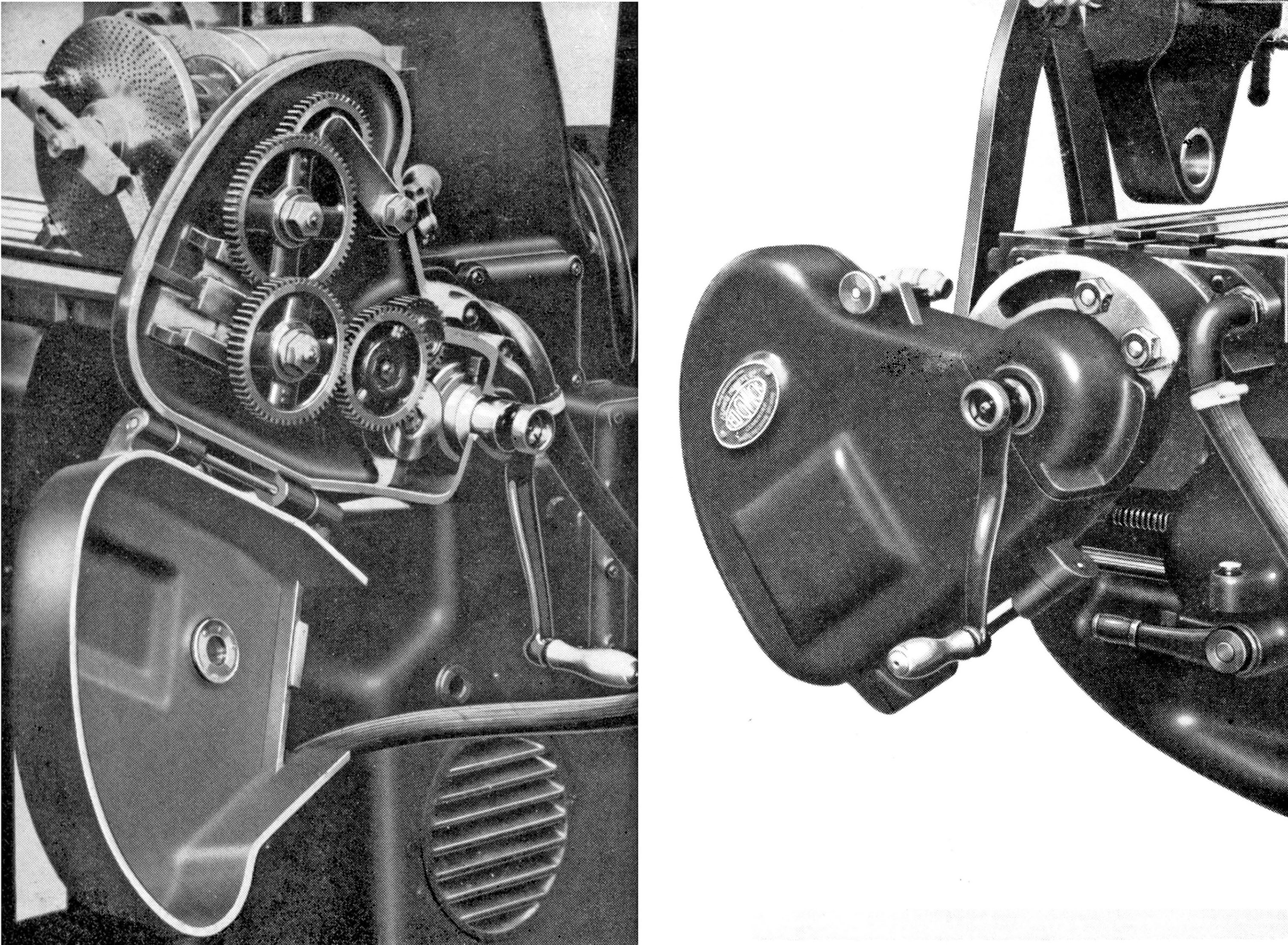
Charged extra together with its push-button operated starter and combined isolating switch and fuse box, the motor was mounted on a plate carried on two eccentric shafts that protruded through the left-hand face of the foot, the arrangement allowing for a quick and easy method of adjusting the drive belt's tension. The driving pulley, 12 inches in diameter and intended to run at 500 r.p.m., could be exposed by removing its cover and might, in some circumstances (as the motor was listed as an extra) have been driven by overhead line shafting, a system that survived in some factories until the late 1940s. Held within the column, the speed-change gearbox was driven through a combined dry-plate clutch and brake unit, this being operated by a long lever pointing forwards and pivoting from a point at the top of the column's left-hand face. Lifting the lever engaged the drive, pressing it down activated the brake. Shafts inside the speed-change gearbox all ran on taper roller bearings with spindle speeds and table feeds selected in the "Cincinnati" way by two dials on the left-hand face of the column. Lubrication of the gearbox was by a chain-driven pump that lifted oil from a sump at the top of the column, this being retuned through a filter and its level in the boxed able to be checked by a sight glass.
Coolant equipment was provided as standard, the supply being delivered by a V-belt-driven pump the drive to which could be engaged and disengaged by a non-rotating knob that projected through the rear guard.
Supplied with each new Universal was a set of overarm braces, full coolant equipment, a 9.25-inch centre height dividing head complete with a tailstock, steady, driver and double-sided index plates, a quadrant and the necessary set of changewheels to mount on it, spindle drawbar, oil gun and all the required spanner and handles and for machines driven from a lineshafting, a belt funnel was also available. I-inch and 1.5-inch cutter-holding arbors were at extra cost
The Universal occupied a floor space of 78" by 66" and weighed approximately 3,600 lbs
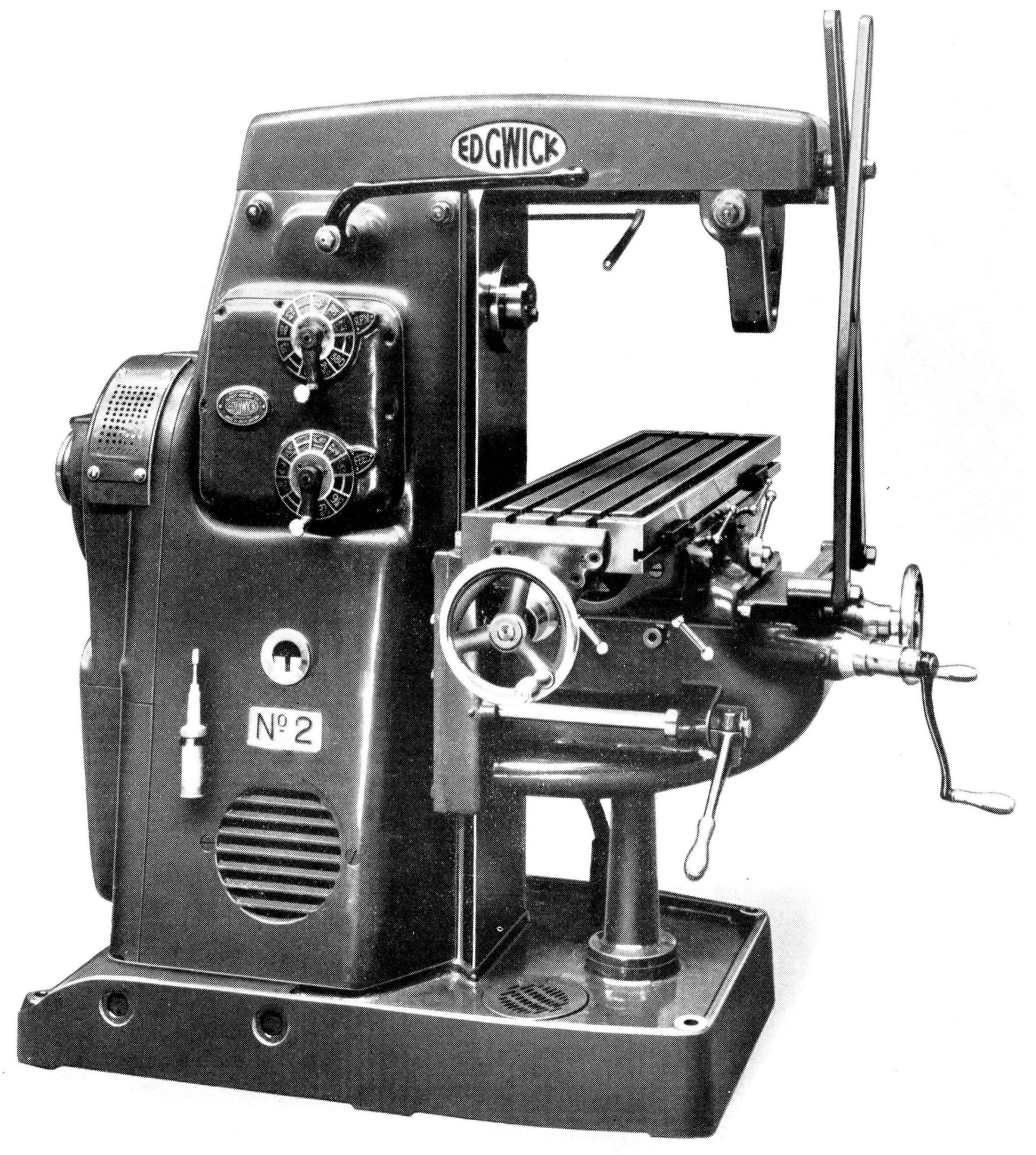
Edgwick Plain Milling Machine No.2
Mechanically identical in design and of the same weight and overall dimensions as the Universal, the Plain model had a smaller 40" x 10.25" (or later 42" x 10.375") non-swivelling table with 25 inches of power-driven longitudinal feed but by hand only on the 7.5 inches of cross feed and 17 inches of vertical. The entire drive system was taken from the Universal model, though the speeds were altered to a choice of nine in a high range from 42 to 745 r.p.m. and a slow range of 21 to 380 r.p.m. As two speed ranges were provided for the spindle, the drive to the table also benefited from the arrangement with nine rates in slow range from 0.5" to 9.5" per minute in fast from 5/8" to 12"..
|
|