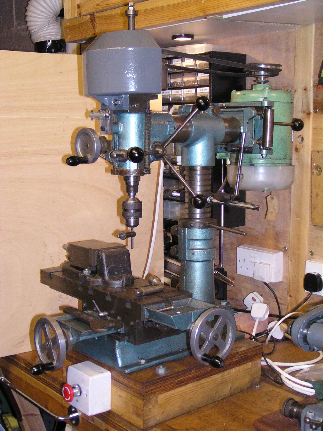
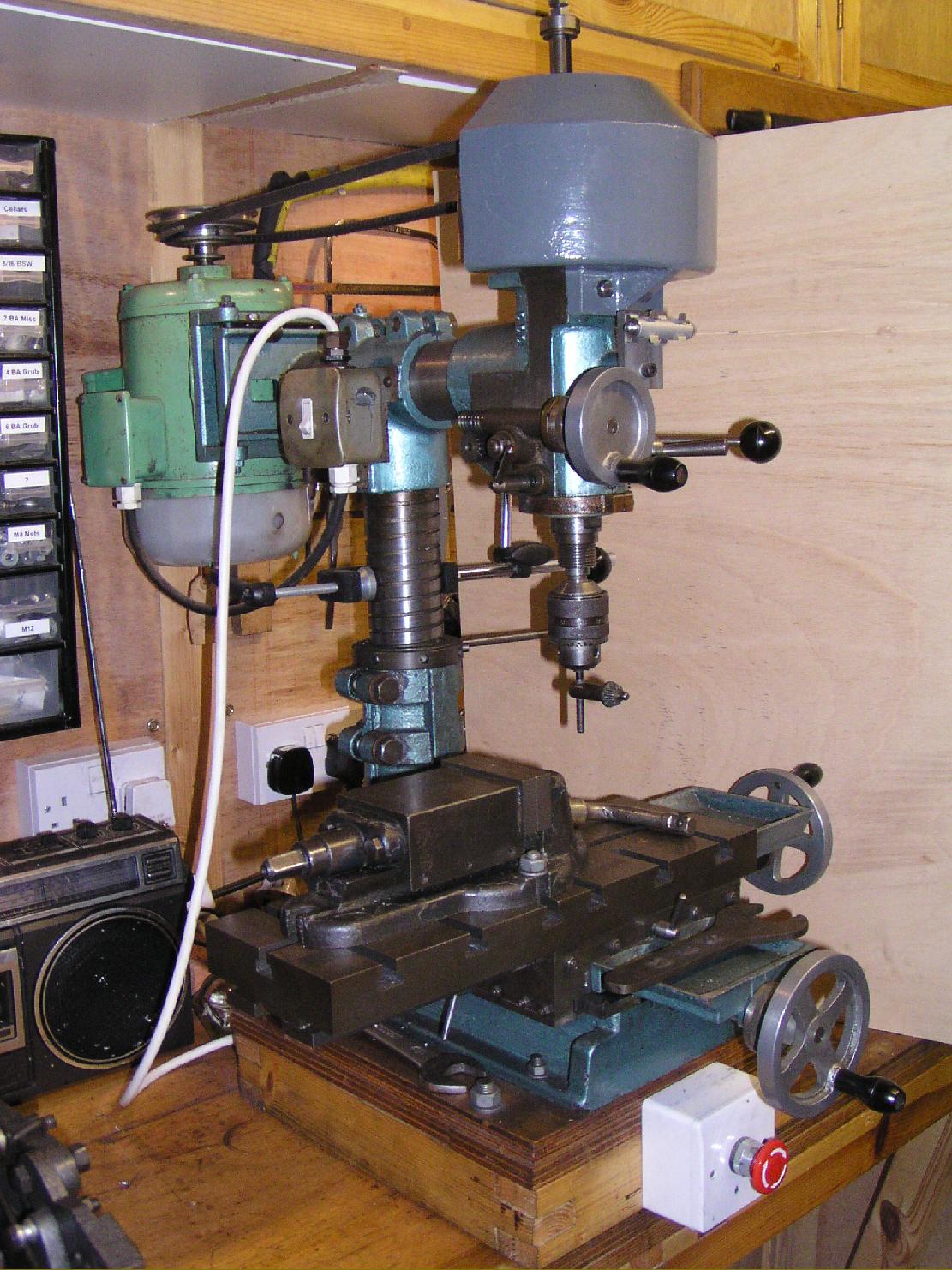
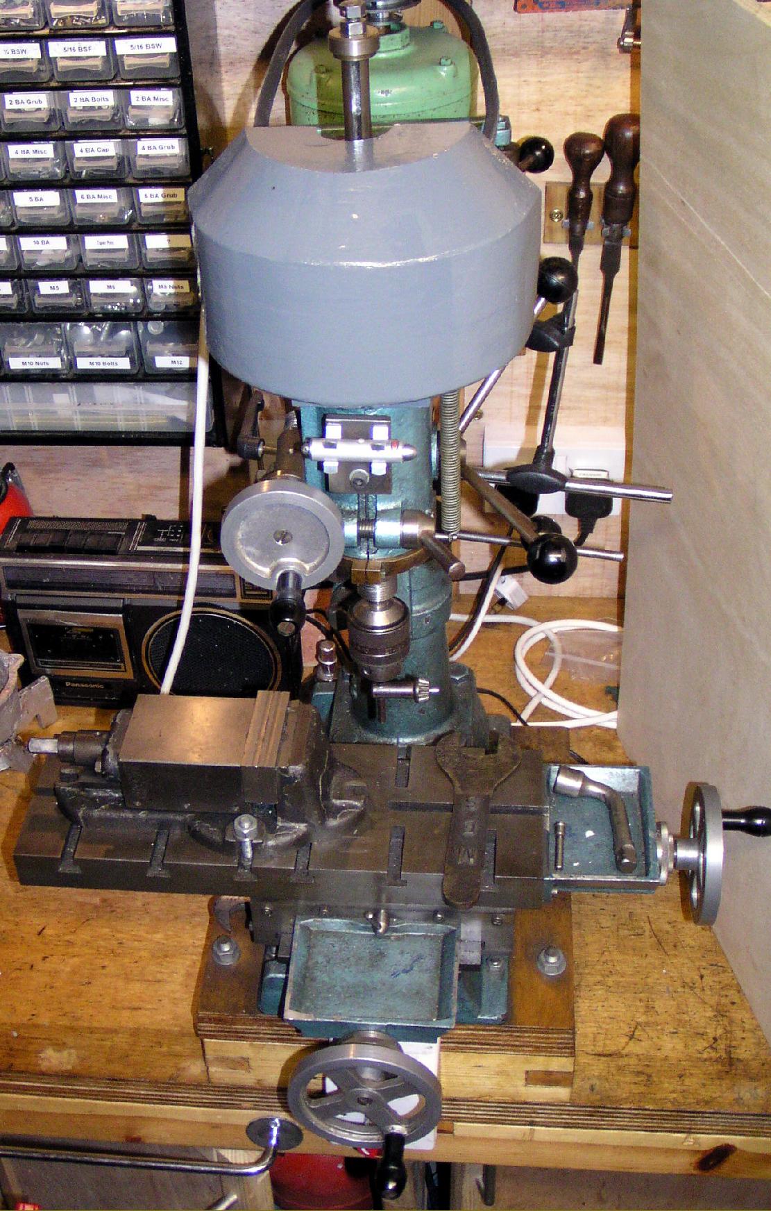
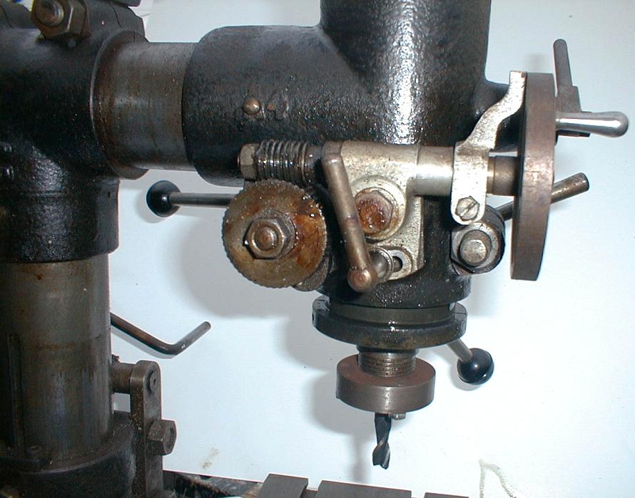
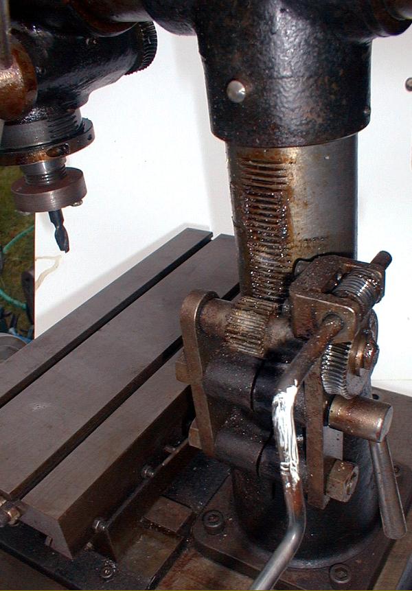
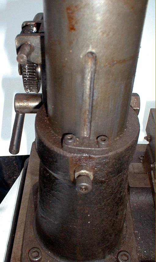
email: tony@lathes.co.uk
Home   Machine Tool Archive   Machine-tools Sale & Wanted
Machine Tool Manuals   Catalogues   Belts   Books   Accessories

Dore Westbury Vertical Miller

Dore Westbury Mk.1 continued here on page 2 (of 2)

Dore Westbury Mk. 2    Dore Westbury Kit of Parts

A set of build instructions and engineering  drawings
are available for the Dore Westbury

Introduced in the Model Engineer Magazine for April, 1964, and named after its designer, Edgar T. Westbury, a well-known model engineer and author. The first version of this popular "home-build" machine was known simply as the "Westbury" (pictures at the bottom of this page) with, initially, sets of casting and drawings made available for the enthusiastic amateur to machine - unfortunately, some proving so large that they were beyond the scope of all but the most generously equipped workshop. In 1967 Arnold Throp C.Eng., F.I.Mech.E. (who lived in the suburb of Dore, Sheffield, South Yorkshire), assisted the designer with a complete rethink - and this resulted in a machine of both greater capacity and improved versatility. Re-named the "Dore-Westbury" the miller went on to become one of the most popular in the model engineering world - for nothing else on sale at the time could offer the enthusiast such a remarkable combination of value, adaptability, speed range and compact dimensions. The marketing of the machine was also revised and the kit of parts soon included the all the larger castings with the bigger machining operating already completed. Everything else could be finished on a Myford ML7, or a similar sized lathe, and a bench drill. Final development of the machine was undertaken by Ivan law, Arnold Throp and Peter Southworth.
In 1971 production relocated to "
Model Engineering Services" in Chesterfield, this Company being run by Ivan Law, an ex-Rolls Royce engineer. The result was revised and even more successful Mk. 2 Model, this offering a number of important refinements including a larger table of 16" x 5.5" with 11" of lengthwise movement and 5" crosswise (Mk. 1 tables seem to vary in size and travel). Too make the most of the table, no fewer than fourteen T-slots, designed to take standard 3/8" bolts and which needed no machining, were cast into the periphery of the table and enormous (almost jig-borer size) micrometer dials could be fitted in place of the tiny ones offered on the Mk. 1.  Instead of a simple coil spring to pull the spindle back up a proper "clock" spring was held in a housing on the left-hand side of the column and the spindle clamping arrangement improved by greatly increasing the size of the boss that drew together the split down the front of the casting. Both the Mk. 1 and early Mk. 2 used epicyclic gearing built into the head to provide low speeds. The Mk. 1 had three direct-drive belt-driven speeds and three through the gears whilst the Mk. 2 was given a considerably improved range of ten speeds - six by belt and four through the gears - it being inadvisable (but possible) to use the two highest speeds through the reduction gearing. On all but late models of the Mk. 2, the epicyclic gearbox used inexpensive, off-the-shelf Myford changewheels and was rather clattery in action. The final machines were re-engineered to incorporate a much-improved set-up with helical gears running in an oil bath, a modification that resulted in a much quieter, smoother and more reliable drive. The range of speeds - approximately 32, 59, 106, 157, 200, 364, 660, 947, 1287 and 1880 r.p.m. - was certainly impressive and added considerably to the miller's versatility. To engage the gears on the epicyclic models one - and sometimes two - small pins have to be pulled out from under the pulley housing. They will be retained either by the friction of an "O" ring or tiny, hard-to-find grub screws. The pins should have been made so that one of them can be passed through the side of the drum into a hole bored in the side of the head casing - so locking the outer ring of the gear unit and allowing the planet wheels to turn and produce a low-ratio drive.
Continued below:


A standard Dore Westbury Mk. 1

The improved Dore Westbury Mk 2

Continued:
What made the machine especially popular was the range of head movements: it could be pushed in and out, rotated about its vertical axis and tilted sideways. Both a rack-and-pinion-driven rapid drill-feed and a worm-gear-driven fine-feed were fitted to the quill and the spindle was provided with a 2 Morse taper internally and the ubiquitous Myford 7 Series (1.125" x 12 t.p.i.) spindle thread externally. However, as an option, it's believed that either a No. 3 Morse or R8 (Bridgeport-type) taper could be provided - though on the thirty or so examples know to the writer over the years none were so equipped.. On Mk. 1 machines the quill travel was 21/8" but on the Mk 2 increased to a much more useful 41/2". The column was milled with a coarse-pitch thread and, running through a large circular fixed "nut" provided with Tommy-bar holes, could be lifted and lowered by passing up and down through the base casting. Of course, to accommodate the full range of movement a large hole had to be bored in the workbench and use of the first drawer was lost as the column descended into it. Besides the standard length, a column 12" taller was available as an option - though even the standard machine could accommodated massive jobs on the table when the head was elevated to its highest position. A table power-feed unit, supplied as a complete kit for home-construction, was made available at around the time of the Mk. 2's introduction.
As one would expect, the quality of finished machines varied enormously and, while many were paragons of engineering virtue and worked superbly, some were rather less well built and consequently less certain and accurate in operation.
Although a Dore Westbury could not take heavy cuts, its wonderful versatility and adaptability more than compensated and so offered the impecunious model engineer (and they all tend to be a bit tight with money) the chance to undertake machining operations that would otherwise have meant buying several other machine tools - and that was the key to its great success.
Production petered out in the late 1990s - it being surprising that it lasted so long as the import of inexpensive, ready-to-run Taiwanese and Korean mill-drills such as the Nareok, Alpine, Sealey and NuTools, etc., had begun in the early 1970s. Although of relatively crude construction and dubious quality, these machine are surprisingly effective - though they all lack the great versatility of the Dore-Westbury..


A very early version of the Dore Westbury with a number of home-engineered modifications

Capstan handle for rapid drill feed of the quill - and the very simple arrangement of the return spring

Worm-and-wheel gearing for the quill fine feed


Home-engineered head-elevation mechanism

Keyway to ensure that, when unlocked and elevated or lowered, the head retained its alignment

Modified epicyclic reduction gearing


Dore Westbury Mk.1 continued here on page 2 (of 2)

Dore Westbury Mk. 2    Dore Westbury Kit of Parts

A set of build instructions and engineering  drawings
are available for the Dore Westbury


Dore Westbury Vertical Miller
email: tony@lathes.co.uk
Home   Machine Tool Archive   Machine-tools Sale & Wanted
Machine Tool Manuals   Catalogues   Belts   Books   Accessories