 |
|
|
|
|
|
|
|
|
|
|
|
|
|
|
|
|
|
|
|
|
|
|
|
|
|
|
|
|
|
|
|
|
|
|
|
|
|
|
|
|
|
|
|
|
|
|
|
|
|
|
|
|
|
|
|
|
|
|
|
|
|
|
|
|
|
|
|
|
|
|
|
|
|
|
email: tony@lathes.co.uk
Home Machine Tool Archive Machine-tools Sale & Wanted
Machine Tool Manuals Catalogues Belts Books Accessories
Denham, Milnes DF4, "Keighley Lifts"
& Bentley Lathes
Literature is available for the Junior and other Denham lathes
Denham SR.8.V and SR.10V Lathes
Denham was an English company, based at the Empire Works in Holmsfield, near Halifax, in what is now the county of West Yorkshire. The firm was started in 1899 by William Denham, a cabinet maker and French polisher, as Denham's Patent Bottling Machine Company Ltd. with premises between Hammond Street and Queen's Road in the centre of Halifax. This venture was an almost immediate failure but, after appointing a new director, Sam Sutcliff, the company began the manufacture of two machines: a small lathe and a slotting machine, both of simple but strong design. A third director, a solicitor called W.H.Bookcock, then joined the enterprise and, by 1907, the Denham Engineering Company had come into being and was beginning to prosper. In 1912 a move was made to the "Empire Works" in nearby Holmsfield - a site the company were to occupy until the 1980s. Denham were eventually to be merged with Churchill Machines Tools (the site-clearance auction was in 1982) and then absorbed into the giant Tube Investments conglomerate to become, finally, part of the '600' Machine Tool Group.
It appears that Denham lathes, regardless of size, were given serial numbers in the order of their production, the surviving lists being (in December of the given year): 1935 = 4182; 1940 = 6231; 1943 = 8355; 1946 = 9105; 1949 = 9636; 1952 = 9967 and 1958 = 10623.
Although in the years following World War Two the company specialised in heavy, high-quality general-purpose lathes and surfacing and boring lathes of up to 28-inch swing, today they are probably best known for one of their smaller lathes, The "Junior", a type used both before, during and after World War 11 by the Army's Royal Mechanical Engineers in both static and mobile workshops. Also badged - due to WW2 requirements, as the Keighley Lifts, Bentley and Milnes DF-4, this sturdy little 41/2" x 24" all-geared-head, gap-bed machine was employed by many educational and training establishments. It was manufactured in both Mk. 1 and (considerably revised and improved) Mk. 2 forms - although, a half-way version has also been found with a Mk. 2 V-bed, an altered saddle, sliding and surfacing feeds but a Mk. 1 headstock with fast-and-loose pulley drive and a spindle bore of about 13/16"). Listed in the first catalogues as the "Denham Junior High Speed Lathe 4 /2-inch" and in later ones (in Mk. 2 form) as the "Denham Junior High Speed Lathe 4 1/2-5-inch Semi-precision" and "DF4 Semi-precision" the makers were obviously hedging their bets about the centre height claiming: "5 inches over the flats and 4.5 inches over the V guides".
Continued below:
|
|
|
|
|
|
|
|
|
|
|
|
|
|
|
|
|
|
|
|
|
|
|
|
|
|
|
|
|
|
|
|
|
|
|
|
|
|
|
|
|
|
|
|
|
|
|
|
|
|
|
|
|
|
|
|
|
|
|
|
|
|
|
|
|
|
|
|
 |
|
|
|
|
|
|
The simple but sturdy Denham Mk. 2 "Junior" 4.5" x 24" Centre Lathe Model DF-4
|
|
|
|
|
|
|
|
|
|
|
|
|
|
|
|
|
|
Continued:
The headstock on the Mk. 1 had a very deep, lift-off cast-iron cover and used a 0.5-inch bore spindle with a 1.5" x 6 t.p.i nose running in plain bearings with speed changes by two separate quadrant levers mounted on front face of the headstock. On the Mk. 2 the headstock was strengthened with a more rigid casting helped by a much smaller, top-mounted bolt-on inspection hatch: the spindle ran in ball or roller bearings (both kinds have been found) and was increased in size to carry a 1.75" x 6 t.p.i. nose thread and had a more useful 3/4-inch bore. The speed-change levers, being mounted concentrically on a common shaft, were easier and quicker to operate - though one had to be aware that, except for their ball-indents, these much more vulnerable levers had no locks and were much more likely to be accidentally struck and moved.
On both lathes the option was offered of either a self-contained or external drive. The built-on drive system had the motor fastened to an adjustable platform on the back of the headstock-end plinth with drive to the headstock from a 0.75 hp 3-phase AC or DC motor by twin V belts through a standard-fit clutch. The flat-belt machine was designed to take its power from a remote countershaft, or overhead line shafting and, to simplify setting up in the workshop, came complete with a neatly-engineered headstock-mounted fast-and-loose pulley system that took a 1.25"-wide belt.
Although the screwcutting arrangements were completely redesigned on the Mk. 2 both machines used a 1-inch diameter, 4 t.p.i. leadscrew with a separate 5/8"-diameter shaft to provide power sliding on the Mk. 1 and both sliding and surfacing feeds on the Mk. 2. Each version could be had with changewheels for screwcutting but the simple 2-lever, 3-change feed-box on the Mk. 1 gave way to a more complex assembly on the Mk. 2 that, strangely, offered no more speeds but an improved action and a lever to change instantly from screwcutting to fine sliding and surfacing feeds. No tumble reverse was fitted: instead both gearboxes contained a reversing mechanism by which means the carriage could be moved in either direction. The standard set of changewheels comprised: 20, 25, 30, 40, 50, 65, 66, 70, 76, 80, 90, 100, 120, 125 - together with a 127 metric translation wheel - and was able to generate inch pitches from 2 to 28 t.p.i and metric from 1 to 10 mm .
On both Mk. 1 and Mk. 2 versions the 10-inch-long saddle and double-walled apron was a massive affair, beautifully engineered with, on the Mk. 1, a two-position quadrant lever to select the sliding feed and a screw-in handwheel to engage it (and thus, unfortunately, no way of immediately releasing the drive). On the Mk. 2 the same quadrant lever selected either sliding or surfacing feeds with engagement and release taken care of (instantly and safely) by flicking up and down a separate lever positioned on the right-hand apron wall. A spring-loaded slipping clutch was fitted to the feeds shaft between the apron and gearbox on the Mk. 2 - not unlike that used on Harrison L4 lathes - to protect the mechanism from excessive loads and to ease the effect of sudden shock loads.
Denham Junior beds were always unhardened , 41/2"- deep and constructed in a "half-box" form. On the Mk. 1 the bed was of traditional "English" pattern with a flat top, 60-degree sides and an "open" gap without a capping section. On the Mk. 2 a dramatic change was made to V-and-flat ways and the gap provided with a bolt-in bridge piece to better support the saddle when working close to a faceplate. . With the gap bridge removed the lathe could turn a piece of metal 15.5" in diameter and 4" thick.
The lathe was supported on a cast-iron box-cabinet under the headstock end (on the inside face of which the electrical control gear was inconveniently and dangerously sited facing sideways rather than outwards) with a simple leg beneath the tailstock; a steel chip tray was standard equipment - when many makers of the time tried to charge extra for this very ordinary, cheap but useful piece of equipment.
A weak point on the lathe was the tailstock - a simple set-over affair fitted with a No. 2 Morse taper barrel, graduated in fractions of an inch, and a crude slot in the casting with a screw clamp to distort it and lock the barrel (a horrid feature, but one found even on some very expensive Swiss Schaublin lathes) - whilst a loose spanner had to be hunted down to lock the unit to the bed.
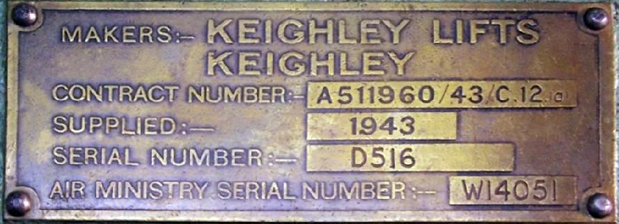
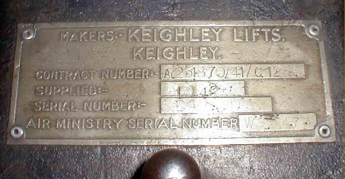
A machine with strong similarities to the Denham was made by a company with what must have been the strangest-ever name for a machine-tool manufacturer, "Keighley Lifts" - whose origins were, naturally enough, in the lift-making business. At the beginning of WW2 Keighley Lifts produced a badged Denham clone for the Ministry of Supply (most of which ended up with the Army). One machine which may have differed from the normal production run was a version of the Mk. 2 that used a plain-bearing headstock; it is understand from a former Keighley employee that most of these Air-Ministry 'specials' were (after use in the 1950s Kenya insurgency) sold on to the Australian Defence Force. Production of the Junior appears to have been helped by other manufacturers as well, examples having been found with "Henry Milnes" cast into their beds and sold using the Model Type DF-4 - this well-known lathe maker being another member of the once thriving Halifax machine-tool community..
|
|
|
|
|
|
|
|
 |
|
|
|
|
|
|
Mk. 2 Denham Junior with V-and-flat bed ways. The 0.75 hp 3-phase AC or DC motor was mounted on an adjustable plate, secured to the back of the headstock-end cabinet, and which rocked on a pivot across its horizontal centre line, The drive belt may have been fully enclosed, but the awkward positioning of the switchgear on the inside face of the headstock-end leg would have left the operator in some danger if things had started to get out of hand.
|
|
|
|
|
|
|
|
|
|
|
 |
|
|
|
|
|
|
|
|
|
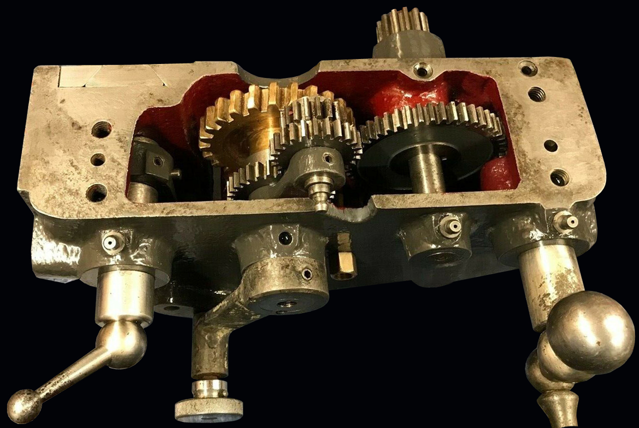
A 3-speed "reversing" gearbox on the Mk. 2 drove both the leadscrew and powershaft and provided three screwcutting ratios and three sliding and surfacing speeds for each setting of the changewheels.
|
|
|
|
|
|
|
|
|
|
|
|
|
|
|
|
 |
|
|
|
|
|
|
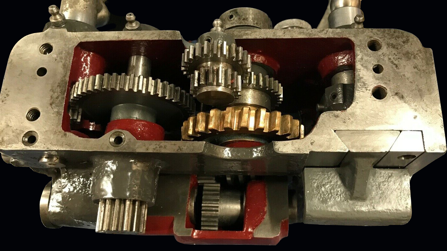
On the Denham Junior Mk. 2 the headstock was considerably improved with a more rigid casting and a much smaller bolt-on inspection hatch in the top: the spindle ran in ball or roller bearings (both have been found) and was increased in size to carry a 1.75" x 6 t.p.i nose thread, had a more useful 3/4-inch bore and with the speed-change levers mounted concentrically on a common shaft. Six speeds were provided, the standard range spanning 30 to 600 rpm, but customers could also choose, at a slightly greater cost, to have this modified to give a rather more useful 70 to 1400 rpm.
|
|
|
|
|
|
|
|
|
|
|
 |
|
|
|
|
|
|
The Denham Junior Mk. 2 headstock was heavily built for a 5-inch centre height lathe and contained a spindle, layshaft and gears all manufactured from high-tensile steel. The simple screwcutting and feeds gearbox was light and positive to operate and gave three pitches and three sliding and surfacing feeds for each arrangement of the changewheels.
|
|
|
|
|
|
|
|
|
|
|
 |
|
|
|
|
|
|
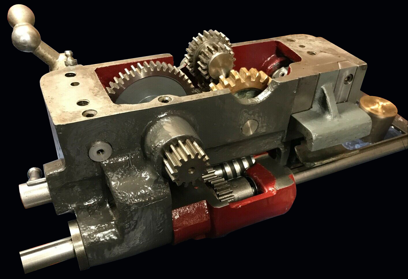
The carriage assembly bore many similarities to that used on the "Keighley Lifts" 4.5" lathe but, unlike that machine, had both power sliding and surfacing feeds - with a convenient and easily-used engagement lever on the right-hand apron wall.
|
|
|
|
|
|
|
|
|
|
|
|
|
|
|
|
|
 |
|
|
|
|
|
|
|
|
|
|
|
 |
|
|
|
|
|
|
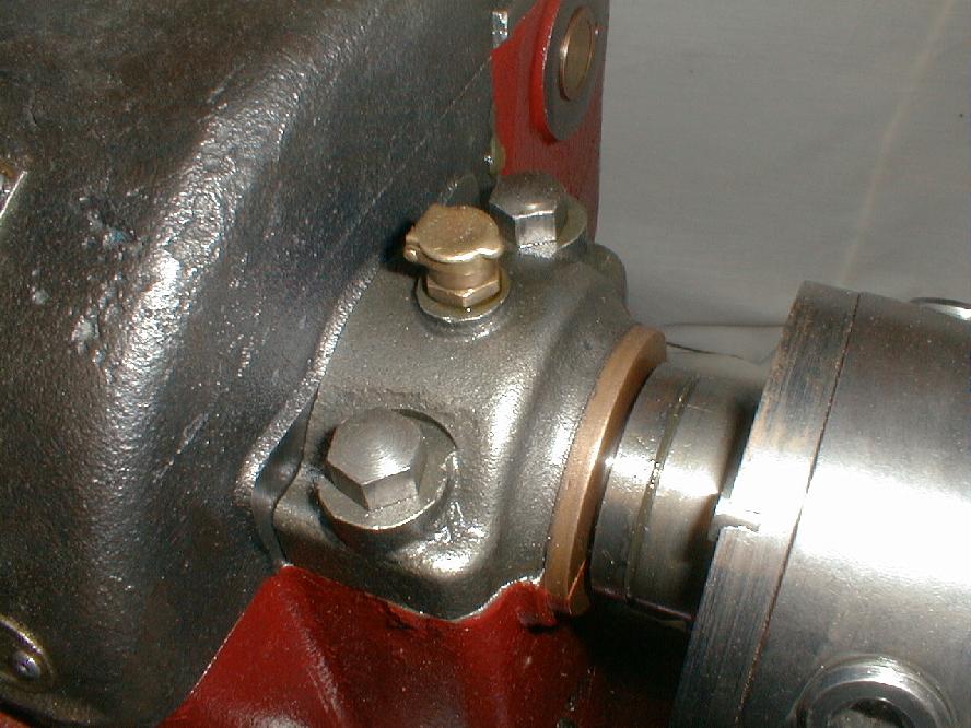
Substantial, bolt-on leadscrew hanger bearing.
|
|
|
|
|
|
|
|
 |
|
|
|
|
|
|
The weakest aspect of the lathe - a simple, set-over tailstock fitted with a No. 2 Morse taper barrel, graduated in fractions of an inch. A crude slot in the casting allowed a screw clamp to distort it and lock the barrel (a horrible feature, also to be found on some models of Swiss Schaublin lathes, which cost many times as much). Whilst a spanner normally had to be found to lock it to the bed - the one fitted in the photograph above is an owner's attempt to solve the problem of the ever-missing, self-hiding spanner.
|
|
|
|
|
|
|
|
|
|
|
 |
|
|
|
|
|
|
Keighley Lifts Lathe - Mk. 1
A machine with many similarities to the Denham Junior, this lathe was made by a company with what must have been one of the strangest names ever for a machine tool manufacturer: Keighley Lifts. Starting out as the Keighley Electrical Engineering Company of Dryart Works, Dalton lane, Keighley in Yorkshire Most examples of the lathe are as illustrated below, a machine obviously adapted from the Denham Junior, yet with many differences. However, it is known that some Denham lathes were simply badged as Keighley Lifts, including versions with the plain bearing Mk. 1 and ball-race or taper roller race Mk. 2 headstocks. Yet another version was fitted with a neatly-made raiser block under the headstock, with correspondingly thickened cross slide and tailstock casting to lift the centre height to around 6.5 inches.
Production of the Denham Junior appears to have been helped by other manufacturers as well, examples having been found with "Henry Milnes" cast into their beds - this well-known maker being another member of the once-thriving Halifax machine-tool community.
Keighley Lifts were known in peacetime for their reliable and widely used passenger and goods lifts and were chosen to build, install and maintain those used in then advanced 1930s high-rise flats at Quarry Hill, in Leeds. Interestingly, these were able to carry only two people and, with almost ninety installed in the complex, provided a steady stream of income as maintenance had to be carried out on a Fourth-Bridge basis - as soon as it was finished, it had to start again. Of course, electing to install lifts with a capacity of just two was a dreadful mistake and impatient residents, often packed six at a time into the tiny shells, were a frequent cause of the safety trip-outs operating and yet another (expensive ) visit required from the company technicians to reset the system. Many textile towns in the cotton and wool-spinning areas of Lancashire and Yorkshire had their own specialist companies devoted to building and repairing the heavy-goods lifts that the giant, multi-story mill buildings needed to operate efficiently; William Wadsworth and Son of Bolton and E.A. Foulds of Colne, Lancashire, being just two of many..
|
|
|
|
|
|
|
|
|
|
|
|
|
|
 |
|
|
|
|
|
|
The Keighley Lifts lathe used the headstock gear-change arrangement from the Mk. 1 Denham
Junior lathe together with the same type of lift-off headstock cover.
|
|
|
|
|
|
|
|
|
|
|
|
|
|
|
|
|
 |
|
|
|
|
|
|
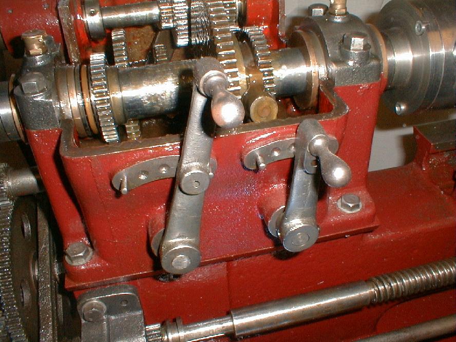
A thoughtful touch was the provision of pin stops to prevent top the speed selector levers over-riding their spring indented locations.
|
|
|
|
|
|
|
|
|
|
|
 |
|
|
|
|
|
|
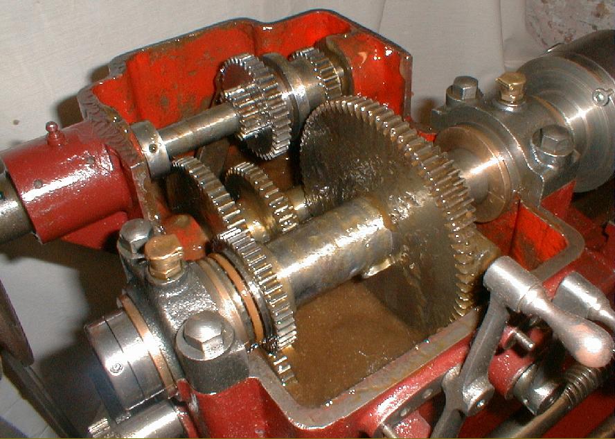
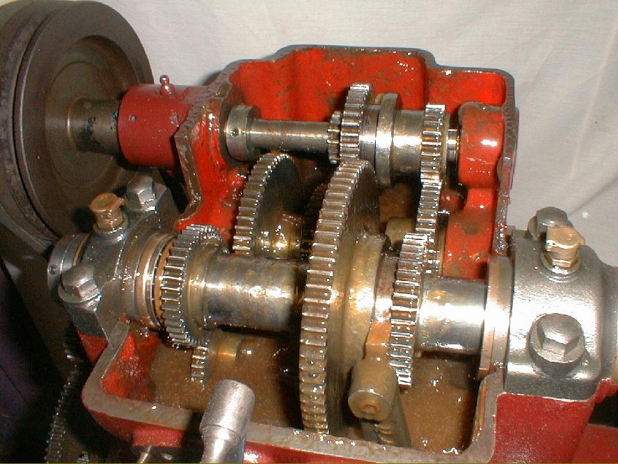
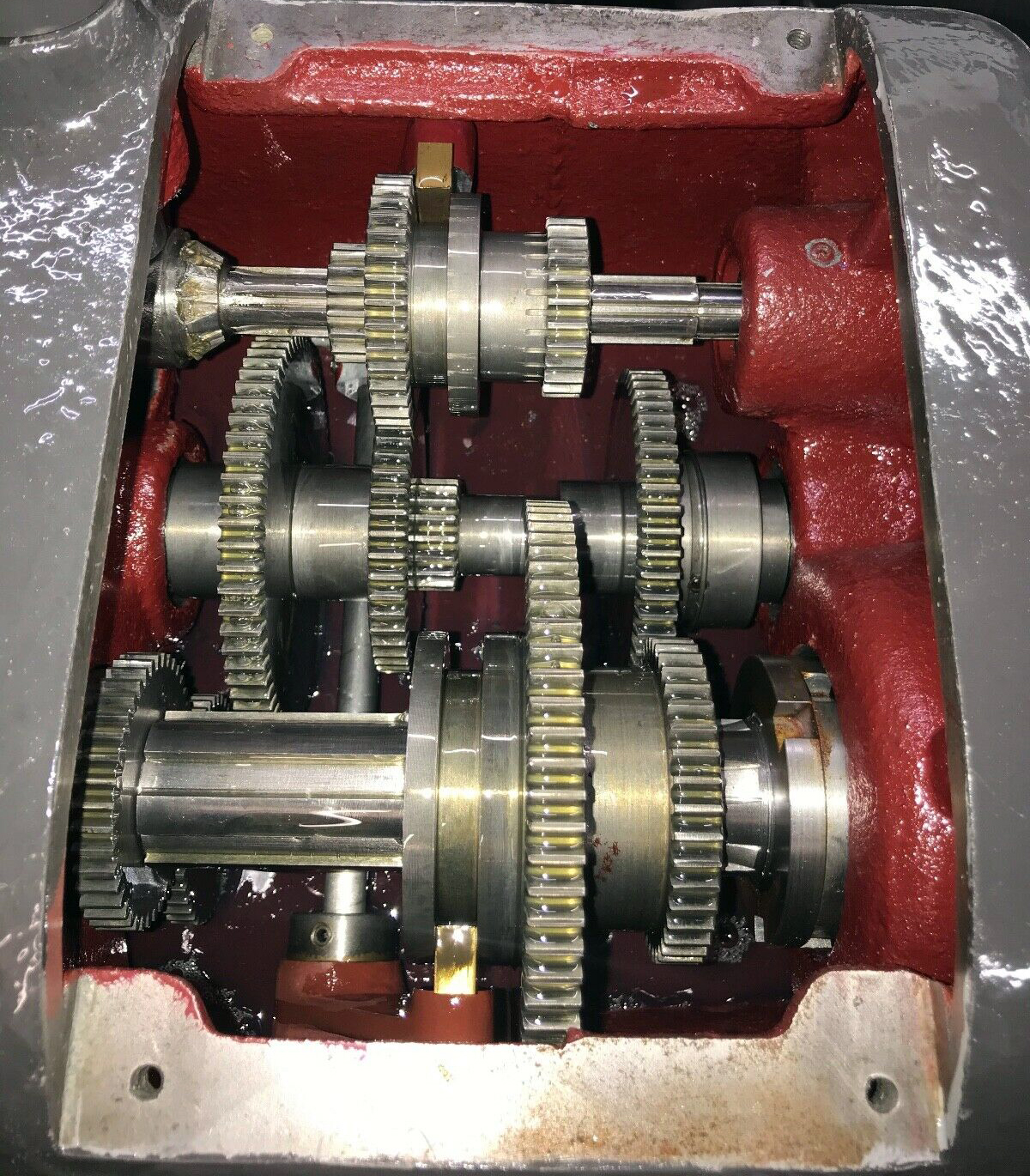
Ignoring the practice of many other makers the designers of the Keighley made the pair of large and small gears on the main shaft (immediately behind the front bearing) part of the set that slid to change speeds.
|
|
|
|
|
|
|
|
|
|
|
|
|
|
|
|
|
 |
|
|
|
|
|
|
The deep headstock top cover was necessary in order to make the bearing caps accessible. Because there was no provision for either a gasket ,or any other type of oil-retention device, a very heavy oil or oil-and-grease mix was used to reduce leaks.
|
|
|
|
|
|
|
|
|
|
|
 |
|
|
|
|
|
 |
|
|
|
|
|
 |
|
|
|
|
|
|
|
|
|
|
|
 |
|
|
|
|
|
|
|
|
|
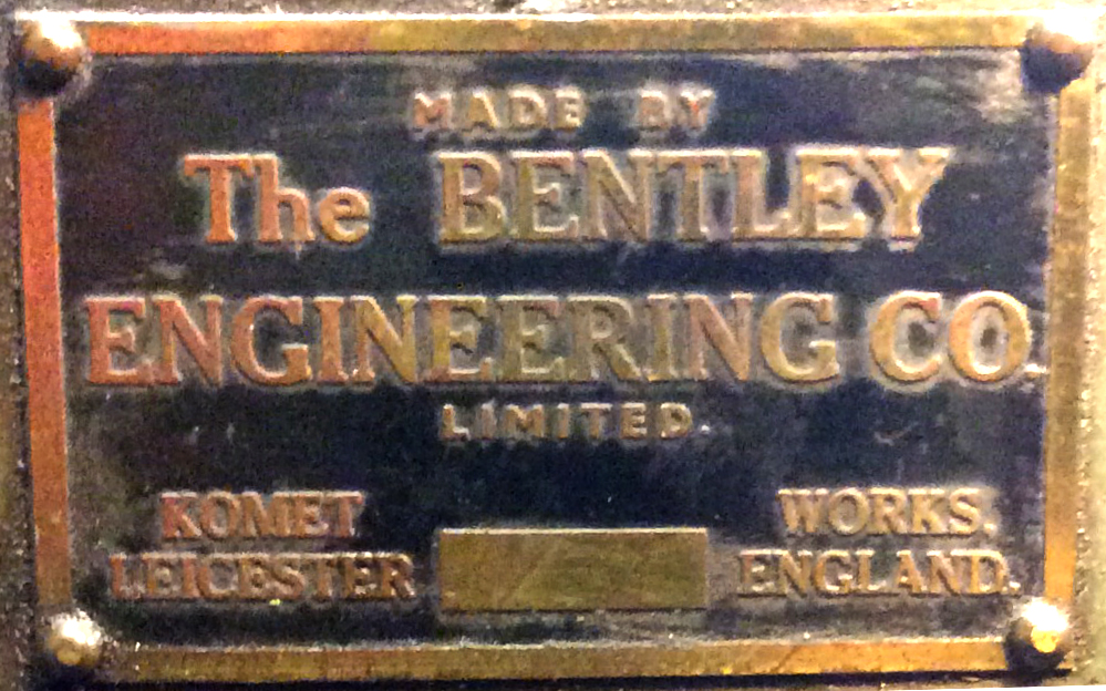
The Bentley Engineering badge found on one example of the Mk/2
|
|
|
|
|
|
|
|
|
|
 |
|
|
|
|
|
|
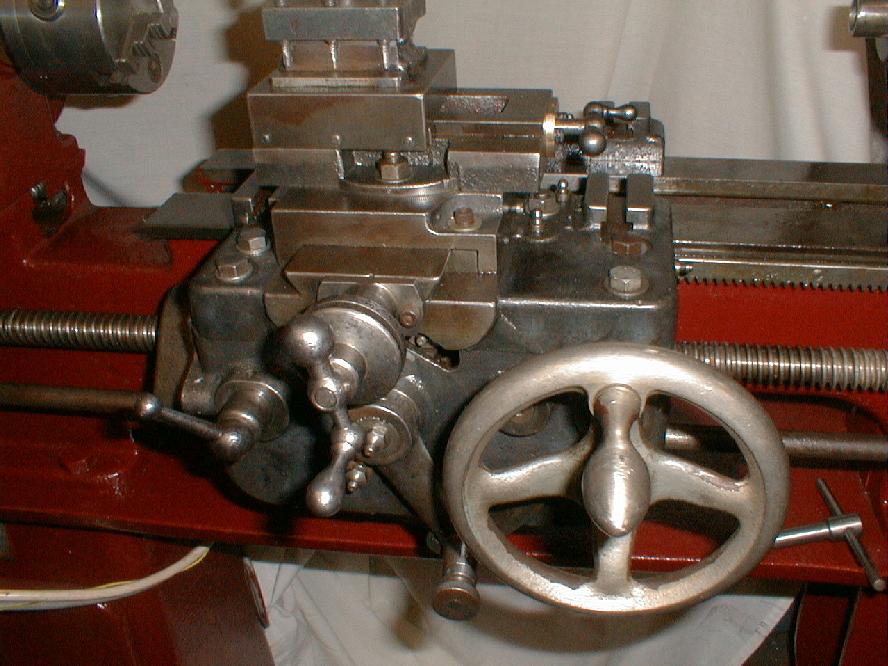
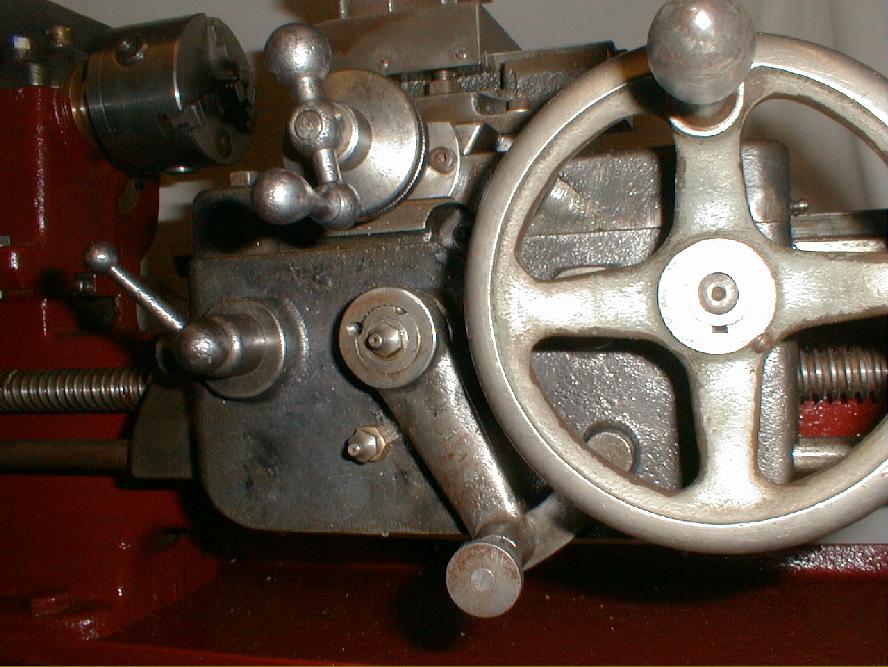
The Keighley carriage featured T slots built into the top surface of the apron and a large, easily gripped handwheel for the manual traverse.
|
|
|
|
|
|
|
|
|
|
|
 |
|
|
|
|
|
|
|
|
|
|
|
 |
|
|
|
|
 |
|
|
|
|
 |
|
|
|
|
|
|
|
|
|
|
 |
|
|
|
|
|
 |
|
|
|
|
|
|
|
|
|
Denham Junior Lathe Mk. 1
|
|
|
|
|
|
|
|
|
|
 |
|
|
|
|
|
|
Whilst the Mk. 1 version of the Denham junior looked very similar to the Mk. 2 there were a number of significant differences with the earlier machine having a traditional English-style flat-topped bed with 60-degree sides. On the version shown screwcutting was by changewheels with a separate powershaft connected to the leadscrew at the headstock end of the bed by a sliding gear. The shaft provided only a power sliding feed, not across, selected by a large lever on the centre of the apron with engagement by screwing in a knob mounted concentric to the lever's shaft. This lathe (and the Mk.2) was also badged as a Keighley Lifts
|
|
|
|
|
|
|
|
|
|
|
 |
|
|
|
|
|
|
Threads and feed gearbox. Only 3 feed rates were available for each setting of the changewheels but the box did incorporate a neat carriage reversing mechanism.
|
|
|
|
|
|
|
|
|
|
|
|
|
|
|
|
|
 |
|
|
|
|
|
|
Denham Mk. 1 Junior lathes awaiting transport to the dispatch department. Some are fully built up with belt and changewheel covers in place others appear to be in the final stages of assembly.
|
|
|
|
|
|
|
|
|
|
|
 |
|
|
|
|
|
|
Dividing attachment for the Denham Junior lathe mounted on its own vertical slide.
|
|
|
|
|
|
|
|
|
|
|
|
|
|
|
|
|
|
|