 |
|
|
|
|
|
|
|
|
|
|
|
|
|
|
|
|
|
|
|
|
|
|
|
|
|
|
|
|
|
|
|
|
|
|
|
|
|
|
|
|
|
|
|
|
|
|
|
|
|
|
|
|
|
|
|
|
|
|
|
|
|
|
|
|
|
|
|
|
|
|
|
|
|
|
|
|
|
|
|
|
|
|
|
|
|
|
|
|
|
|
|
|
|
|
|
|
|
|
|
|
|
|
|
|
Built in England by Churchill Redman Ltd. in both Halifax (Yorkshire) and Scotswood (Tyne and Wear), the 6" x 20" (later 6.5" x 24") gap-bed Cub lathe was built (as far as evidence from date-coded catalogues and older employees reveals) from 1933 until the early 1960s and given the Registered Design Number 788433. A careful examination of the pictures on this page will show that the lathe went through a steady process of improvement that involved both major and minor revisions with, alongside other improvements, an increase in top speed from the original lowly 400 to a much more useful 1000 r.p.m. Although the Scotswood plant made a number of different lathes (some of which were destined for Indian Railways and purchased through the Crown Agents) evidence of how relatively slow Cub production was during the 1950s comes from the fact that a single foreman, Jim Kennedy (who had originally worked on the lathe in the Halifax plant), was solely responsible for their final assembly. The headstock taper roller bearings on the Mk. 1 Cub were by Timken with the front having an outer race Timken part: 2720 and an inner roller section Part 2788. The left-hand bearing was numbered 2631 for the outer track and roller section 2687.
In August 1957 the name of the Company changed to "Churchill-Gear Machines Ltd." and a move was made to a new factory across the river at Blaydon-on-Tyne. Even though the title had been changed the firm continued trading under its original name - and the factory signs in Halifax were not altered. Unfortunately, this promising development was followed by a large-scale redundancy in early 1958 and this, together with increasingly stiff competition from Colchester and their mass-produced Student and Master models, would have signalled the end of the Cub's life. By 1960, in a desperate effort to cut production costs, the works apprentices were drafted in to build the lathe. Quite how the company evaded the wrath of the unions is unknown but, apart from final painting, the lads did all the work themselves including machining the parts. The young men were quite aware that the Company did not make any mention of this in their sales literature - and were somewhat aggrieved (having accepted the responsibility for the job) when the universally disliked works manager was seen posing proudly by a finished machine for a publicity photograph.
Continued below:
|
|
|
|
|
|
|
|
 |
|
|
|
|
|
|
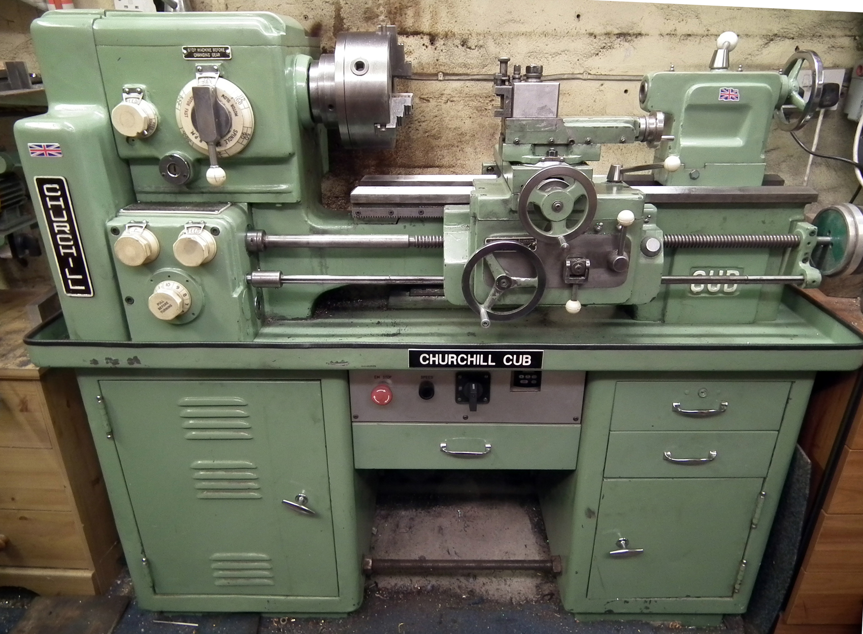
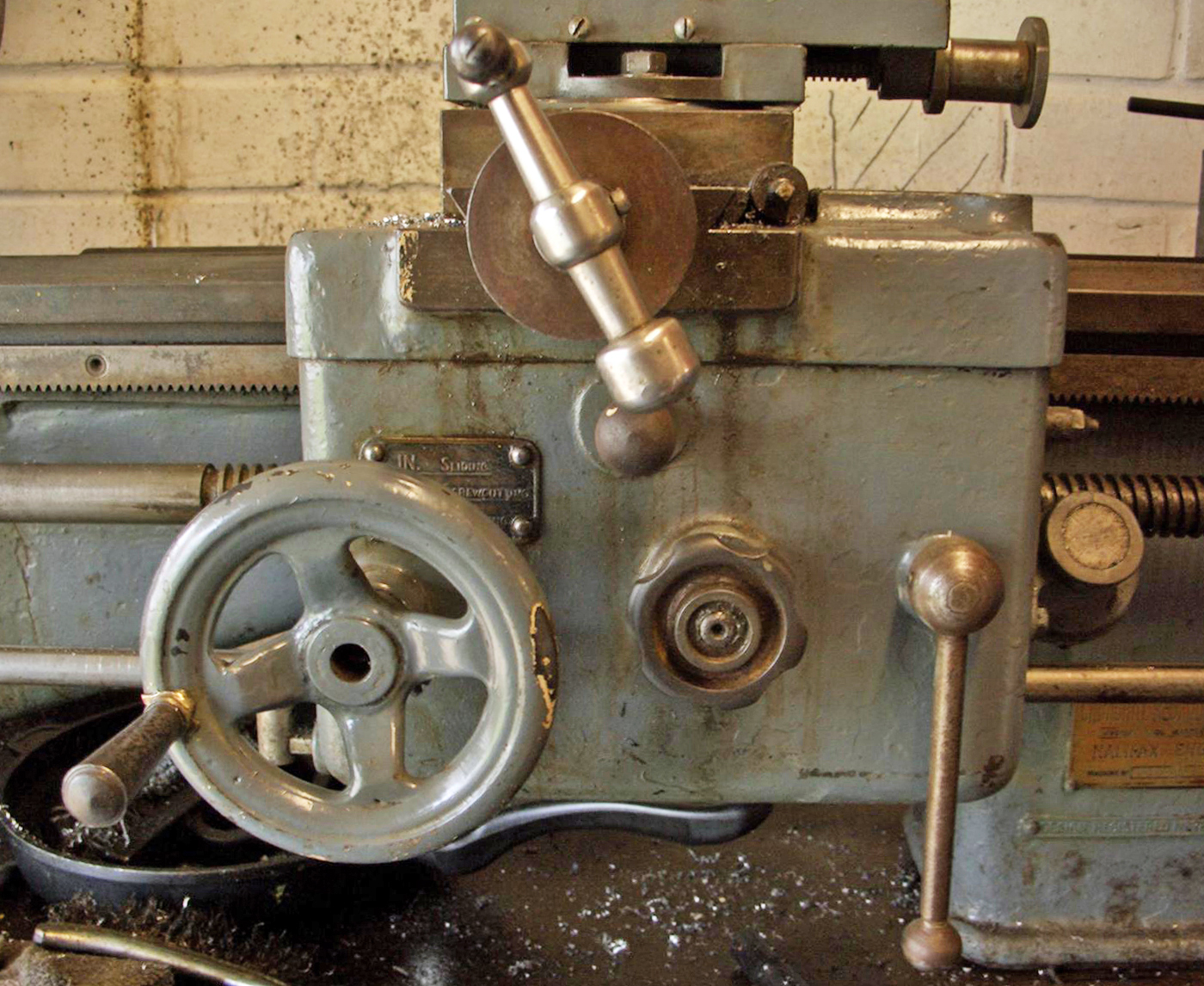
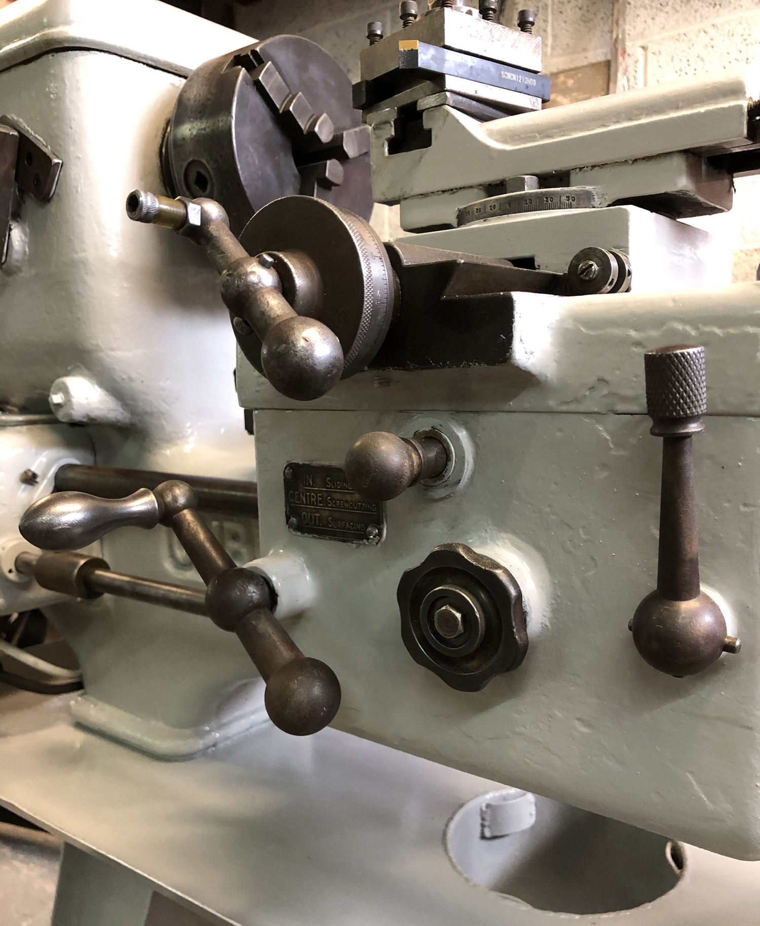
Churchill-Redman "Cub" Mk. 3 as supplied during from late 1940s until the 1960s. The cam-action lever on the face of the apron engaged and disengaged the power feeds and was a considerable improvement on the slow-to operate screw-in-and-out knob used on earlier versions.
Continued:
Although both the registration of the original design, and patents, were applied for in the early 1930s, it was not until February 3rd., 1948 (and the introduction of an almost entirely different model) that anything seems to have come of this with two Design Numbers (843,456 and 844,892), together with a Patent (597764), being granted - the latter concerning an ingenious method of selecting spindle speeds. Being compact, but having a generous capacity for its size, the lathe quickly became popular with training establishments, commercial engineering companies and the Armed Services with many examples supplied to the Royal Navy for use in submarines during WW2. As a consequence of its widespread adoption by official bodies many, still in lightly-used condition, eventually found their way onto the surplus market and are still in use today.
It appears that some five versions of the cub were produced that we shall call, for convenience the Mk. 1, Mk. 1a, Mk. 2, Mk. 3 and Mk. 3a - all very easily distinguished one from the other: the Mark 1 can be recognised by its one-piece bed and headstock with the latter of square appearance and all the control levers for speeds, threads and the selection of power feeds being tapered arms with acorn-shaped ends. The Mk. 1a appears to have been mechanically identical but fitted with distinctive "bent" control levers; the Mk. 2, a machine with more rounded styling, had bolt-on headstock and was fitted with neat (if rather large and smooth-faced) full-circle "hexagonal" controls (that replaced all the levers). The Mk. 3, in its first form, employed just two headstock-mounted rotary controls and a simple screwcutting and feeds gearbox with a single lever on top to select (it is believed) three changes of pitch and feed for each setting of the changewheels. Of heavier build, the apron resembled that of the Mk. 2 with button selection of sliding or surfacing feed and engagement by a wind-in-and-out star wheel with the 4-spoke carriage handwheel positioned (rather unusually) almost in the centre of the casting. The final version, the Mk. 3A had a full screwcutting and feeds gearbox with three dials on the front cover, better guarding of the changewheels under a heavy cast cover, a more massive top to the headstock and a revised apron with a quick-action toggle lever to engage the power feeds. It might be that other, interim models were also manufactured with so far unrecorded minor changes to the design - though if this is the case, these versions almost certainly never appeared in the sales literature
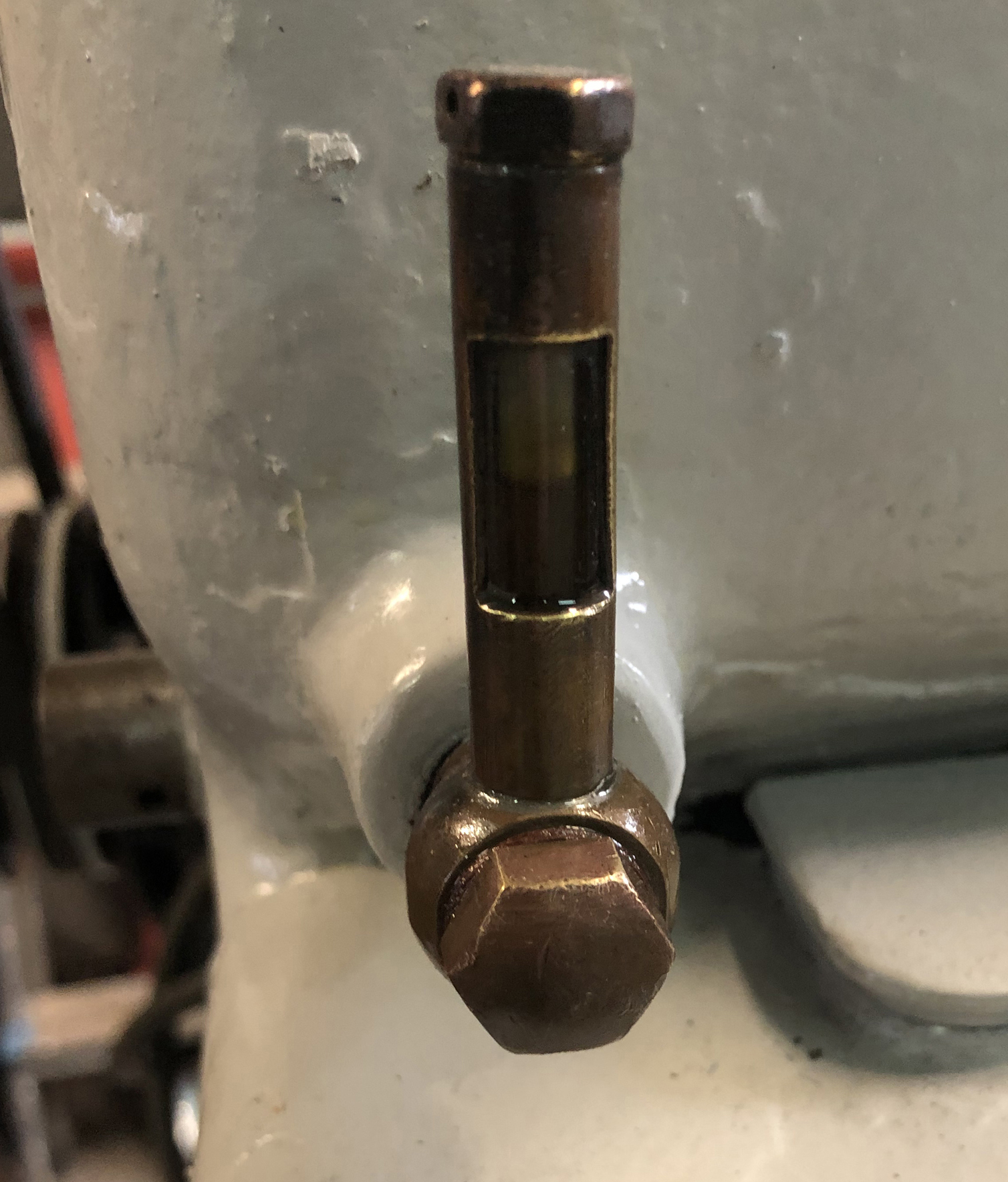
On its introduction, the Cub's closest direct competitors were probably the geared-head 41/2-inch Denham Junior and (rather old-fashioned) 5-inch flat-belt drive Colchester Bantam. It managed to outclass both of them by offering a centre height of 6-inches, 24 or 36 inches between centres, the ability to swing a piece of material 16 inches in diameter by 4-inches thick in the gap and a useful speed range (powered by a 3/4 h.p. 1500 r.p.m motor bolted to the back of the bed) of: 25, 44.5, 81, 142, 250 and 457 r.p.m. As an alternative, and achieved by a more powerful motor and a change of pulleys, the speeds could be arranged to run from 50 to a more useful top speed of 900 r.p.m. Drive to the all-geared headstock was by twin (and then still novel) V-belts - thought at the time these were commonly referred to as "tex ropes" - with speed changes by the juxtaposition of two levers on the front face of the headstock. Much play was made by Churchill of the lathe's material specifications and heavy build, the inverted V-way bed and headstock were cast as one and, although strictly speaking the bed was not hardened, the cast iron (with the advertising puff of being described as "semi-steel") was to Brinell 200. While the two headstock layshafts with their nickel-chrome, 65-ton tensile steel gears rotated on ball races the 9/16" bore main spindle was fitted with Timken taper roller bearings set up to absorb both radial and thrust loads. The gears ran in a simple splash oil bath (with a rather venerable vertical glass oil-level indicator on the front of the headstock) with the headstock cover, and guards over the changewheels and motor-to headstock drive belt, in cast aluminium. Before dispatch from the works each Cub was run-in and the spindle bearings set up to eliminate the need for adjustment for "a number of years".
Drive to the (oil-bath) three-speed screwcutting and feeds gearbox was by a train of conventional changewheels; however, instead of the expected externally-mounted tumbler to reverse the leadscrew and feed shaft an internal gear mechanism was neatly built (like a larger lathe) into the headstock where the fast-running gears benefited from a constant supply of lubricant. The leadscrew was used only for screwcutting (a lever was provided to disengage it from the feedbox) with the sliding and surfacing feeds being driven by a separate power shaft; the double-walled, oil-bath apron mounted a central push-pull button to select the feed (along the bed or across) and a screw-in handwheel to engage the drive through a cone-type friction clutch. On Mk. 2 lathes the selector lever was changed to a flick-left-and-right type, but the cone clutch remained. The right-hand face of the apron was fitted as standard with a thread-dial indicator but, instead of a sight-glass that showed the state of the oil level at a glance, a simple flip-top oil cup was supplied that required the operator to open, check and top up as necessary.
Continued below:
|
|
|
|
|
|
|
|
|
|
|
|
|
|
|
Continued:
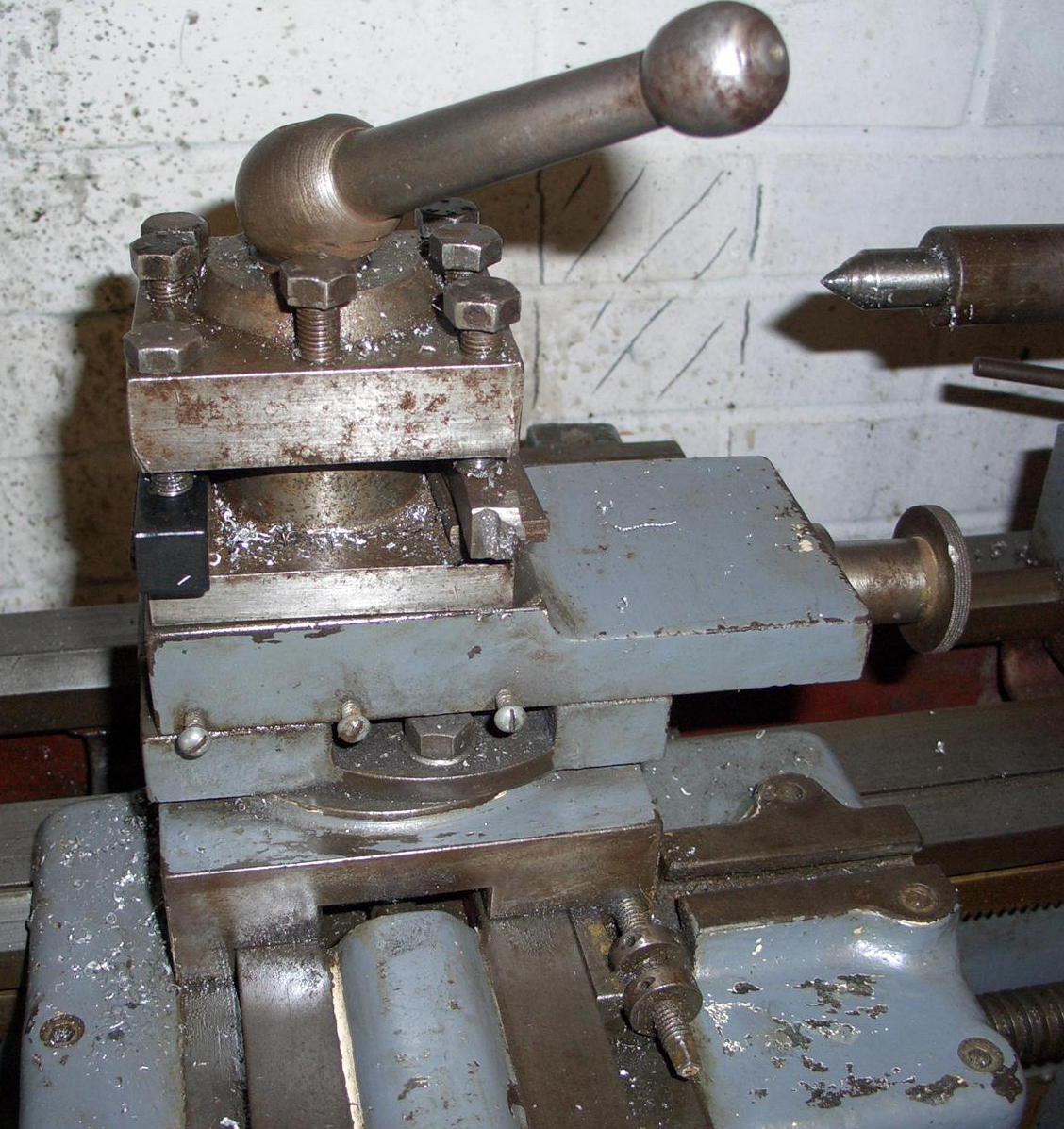
Fitted with taper gib strips the compound slide rest was equipped with decent "balanced" handwheels and what were, for the time, good-sized micrometer dials. Unfortunately, the cross slide was of the short type, but at least with a stout, cast-iron cover at the back to protect the end of the feed-screw from the wearing effects of swarf and dirt.
Early versions of the lathe have been found mounted on a pair of heavy-gauge, pressed-steel, all-welded legs complete with a chip tray while later variants were also available on "semi-cabinets" with a welded sheet-steel box structure at the headstock end of the bed and a simple leg, in cast iron or pressed steel, at the other.
Although a sound lathe, by the end of World War Two the Cub was looking decidedly old-fashioned and, to address the situation, Churchill embarked on a complete redesign. The resulting Mk. 3 was not only more modern and powerful-looking but also incorporated numerous mechanical improvements that allowed the lathe nearly another 20 years of life. The new model was not only well engineered but of especially heavy construction, weighing some 1232 lbs (559 kg) - as much as a Colchester Student - yet it was very compact and needed a floor space of only 5 by 2 feet. By the standards of the 1940s it had an excellent basic specification and was delivered mounted on a neat, all-welded cabinet base. The stand housed the motor, its control gear and had built-in coolant equipment; the centre portion contained the electrical switchgear (and sometimes a drawer) while the right-hand side had two drawers (one of which could be locked to hold the operator's personal belongings) and a cupboard. The headstock, designed to absorb the rigors of industrial use, had an oil-splash lubricated, all-geared taper-roller bearing spindle controlled by a combined spindle clutch and brake. Sliding and surfacing feeds were driven by a separate 5/8" diameter feed shaft working through an oil-bath apron. A removable gap in the bed allowed material 17.5 inches in diameter and 4.375 inches thick to be turned while a sealed, oil-immersed screw-cutting gearbox was fitted as standard. The original finish - at least of the later models - appears to have been a rather dark shade of the standard "British machine-tool grey".
The same reasons that made the lathe appeal to sub-mariners should also attract the home-user today: a rugged build, generous centre height with an enormous capacity in the gap, a reasonable between-centres distance, versatile performance, compact dimensions, a capacity to endure serious rates of metal removal - and all at a price well below that asked for other modern machines of a similar size (if better specification) - the Colchester Bantam and Harrison M250, for example. Of particular interest to the amateur, who may have to transport his own machine and then install it in an inconveniently-sited workshop, is the ease with which all but the Mk. 1 Cub can be dismantled into its component parts; competent mechanics have been known to remove the tailstock, carriage, gearbox and headstock in about 15 minutes leaving a naked bed attached to a now easily-moved cabinet; the same job on a Bantam or M250 will take the best part of an entire morning.
Continued below:
|
|
|
|
|
|
|
|
 |
|
|
|
|
 |
|
|
|
|
|
|
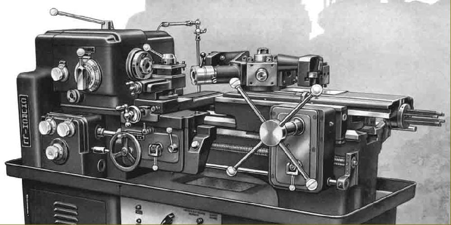
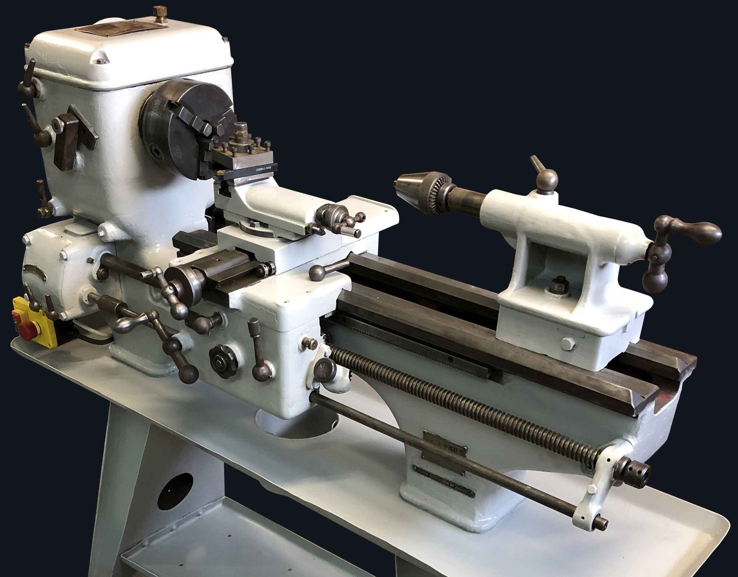
Cub Mk. 3A. One interesting addition to the usual accessories (a taper-turning unit, large faceplates, collets and fixed and travelling steadies) was a powered 6-station self-indexing capstan slide attachment (with 6 inches of tool travel) that fitted in place of the tailstock yet left the standard carriage undisturbed.
|
|
|
|
|
|
|
|
|
|
|
|
Continued:
Hand scraped until it was a perfect fit on the bed, the separate headstock carried a 3/4" bore spindle supported in a pair of opposed Timken taper-roller bearings at the front and a roller bearing at the rear. The spindle nose appears to have been Churchill's own adaptation of the standard "Camlock" flange - but with 3/8" Allen screws instead of studs - and carried a No 3 Morse taper; Pratt Burnerd apparently retain a pattern of the Churchill mount and are able to supply new chucks with the proper fitting built in. All the gears had shaved teeth and were hobbed from nickel-chrome, heated-treated steel with the speed changes made by a single rotary control conveniently sited on the front face of the headstock. The other headstock shafts (as they had on the Mk. 1 and Mk. 2) revolved in ball races.
Consisting of an under-slung, 2-speed, 3-phase motor mounted on an adjustable plate (to allow for belt tensioning) the standard drive system ran at 960 and 1400 rpm with drive to the geared-headstock input pulley using two M-section V belts. This arrangement gave 12 spindle speeds in a range that, while it varied over the years, was typically 45 to 900 rpm on very early machines - though with some (probably for use in training establishments) with a much lower top speed of 400 rpm. Later models were given a somewhat improved range (although the top speed was still a little slow) of: low-range 32, 60, 112, 190, 356 and 665 rpm and high-range 48, 90, 168, 285, 534 and 1000 rpm. In today's faster world, if the owner's work demands a higher top speed then it is unlikely that the roller-bearing headstock will protest (although the motor might) if the top speed is lifted to some 1500 rpm or so by using a larger pulley on the motor shaft. Not all machines however were fitted with the two-speed motor, as both single-speed AC and DC units were available as options, the former likely to have been specified when used in a training role. When fitted with a single-speed motor, six speeds were available with a choice of two ranges, either 48 to 1000 rpm or 32 to 665 rpm. The headstock input pulley incorporated a multi-plate disc clutch the design of which was improved in 1948 from machine number 16048
Ground-finished from a substantial and heavily cross-braced casting, the massive bed carried double-Vee slideways, one for the saddle and one for the tailstock, and was fastened to its cabinet by four 3/8 Whitworth setscrews - but not shimmed or levelled in any way; a simple plain cardboard gasket was used to seal against coolant leaks into the cabinet while the detachable gap bridge was secured by four Allen screws.
The compound slide rest was fitted with proper taper-gib strips and large, zeroing micrometer dials with the top slide able to be swivelled through 360 degrees. A steel 4-way tool post was fitted as standard.
Of double-walled construction, the apron held an oil bath in its base with all the shafts, supported at each end, running in easily-replaced bronze bushes. While the sliding and surfacing feeds were still selected by the same lever arrangement from the Mk. 2 (that was flicked left and right from its central, neutral position) they were now engaged and disengaged by a quick-action toggle lever whose action allowed the drive to be instantly released - a considerable improvement over previous slow-to-operate wind-in-and-out knob. The power feeds were also arranged to work through a spring-loaded, safety clutch built into the drive shaft just before it entered the feed box; as before, a thread-dial indicator was fitted as standard.
Screwcutting was taken care of by a 4 t.p.i. 7/8" in diameter leadscrew driven from an enclosed, splash-lubricated gearbox operated by two dials and capable of generating 30 pitches from 10 to 76 t.p.i. and 30 sliding feeds from 0.001" to 0.0076" per revolution of the spindle. While the sales literature claimed that additional changewheels of 30t, 60t, 60t, 110t and 120t were provided with each machine to extend the threading range from 2.5 to 75 t.p.i. (and the feeds from 0.001" to 0.030"), an examination of machines in use appear to indicate that the original gear train (for a gearbox-equipped lathe) used a 30t drive gear, 110t idle gear and a 120t gear on the gearbox input shaft. Stored outboard of the idler gear and gearbox input shaft were gears of 45t and 50t - but with no sign of the 60t gear. At extra cost an additional nine (unspecified) changewheels were available to generate metric pitches from 0.20 to 8.0 mm pitch (these likely to have included a 127t or 63t.) The surfacing feeds were set at the usefully fine rate of one-fifth those of the sliding.
Although the structure of the tailstock was entirely ordinary, the method employed to lock it to the bed was not: a handle (conveniently positioned at the top of the casting) was rotated in a horizontal plane and, through a captive nut, drove a system of levers that pivoted inside the tailstock body and drew up a locking plate firmly against the underside of the ways. Conventional parts of the tailstock included the set-over base, locked with two screws and the No. 3 Morse-taper barrel, fed by a screw and handwheel, with a travel of 3 inches, and self-eject for the centre.
Coolant was distributed from a gear pump attached to the rear of the bed below the headstock and driven by a V-belt from the rear of the headstock spindle. Cutting fluid was taken from a small tank in the cabinet and fed along a pipe inside the bed to an outlet union part way along it.
One interesting addition to the usual accessories (a taper-turning unit, large faceplates, collets and fixed and travelling steadies) was a 6-station self-indexing capstan slide attachment (with six inches of tool travel) that fitted in place of the tailstock - yet left the standard carriage undisturbed. Once very popular, this fitting allowed a small machine shop to gear up for short productions runs without having to find the space and money for a (at the time) hard-to-find small capstan lathe. Unusually, instead of being just bolted to the bed - as were the vast majority of similar capstan heads offered by competing companies - this was a fully powered version, driven from the feed shaft, that turned the lathe into a unit capable of serious work.
Charles Churchill and Churchill Redman made (and also marketed in collaboration with other manufacturers) a wide variety of other machine tools including toolroom, automatic, heavy-duty, centre, hydraulic-profiling, surfacing and boring lathes; shaping machines, Churchill-Cleveland hobbing machines and Churchill-Red Ring gear shavers.
If any reader can provide photographs, advertising catalogues or other literature and information relating to the very early models of the Cub, the writer would be pleased to hear from you..
Churchill Cub Continued here
|
|
|
|
|
|
|
|
|
|
|
|
|
 |
|
|
|
|
 |
|
|
|
|
|
|
The Mk. 3A Cub, built from the late 1940s onwards, was offered with the option of modern-looking, neatly-constructed fabricated-steel cabinet stand with the left side containing the motor, the centre portion the electrical switchgear (and sometimes a drawer) and the right side two drawers (one of which could be locked to hold the operator's personal belongings) and a cupboard.
Early versions of the lathe, both Mk. 1 and Mk. 2 have been found mounted on heavy, pressed-steel legs and also on "semi-cabinets" - where a box structure of heavy-gauge pressed steel supported the headstock end of the bed and a simple leg, in cast iron or pressed steel, the other.
|
|
|
|
|
|
|
|
|
|
 |
|
|
|
|
|
|
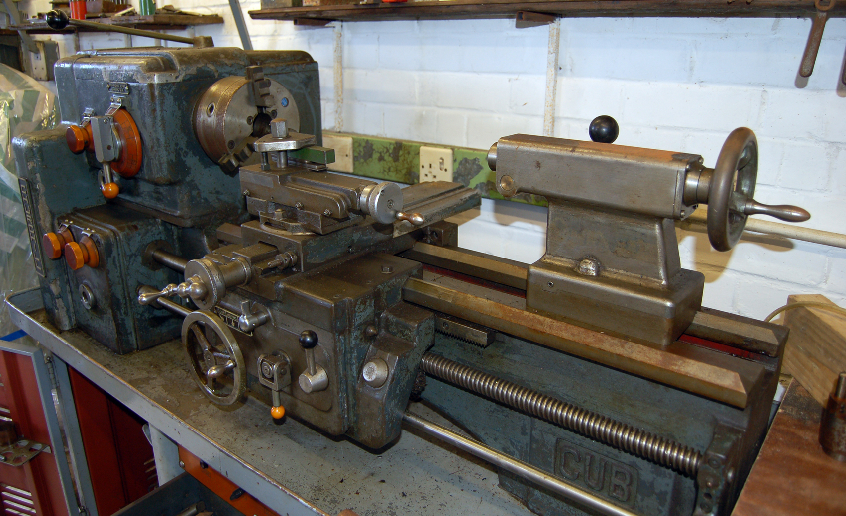
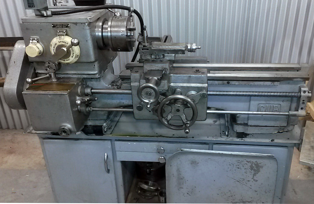
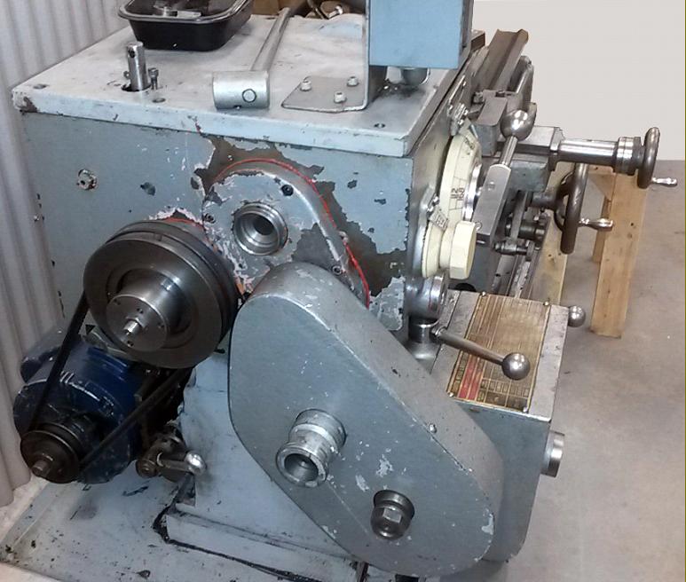
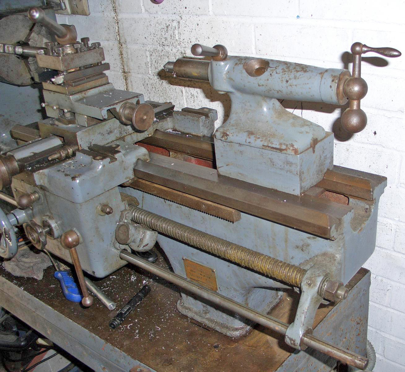
A rather different machine the early Mk. 3 Cub had (in the form shown) a simplified (probably 3-speed) screwcutting and feeds gearbox, different apron controls and a rather perfunctory cover over the changewheels. The screw-in clutch on the apron to engage the power sliding and surfacing feeds (as used on the Mk. 2) would confirm this as an early version - the more frequently encountered and presumably later Mk. 3A having a quick-action toggle lever. In addition headstock cover is also rather lighter in construction and the lathe lacks the neat, built-in electrical controls found on all late models.
|
|
|
|
|
|
|
|
|
|
|
|
 |
|
|
|
|
 |
|
|
|
|
|
|
Capacity chart of the standard lathe.
|
|
|
|
|
|
|
|
|
|
 |
|
|
|
|
|
|
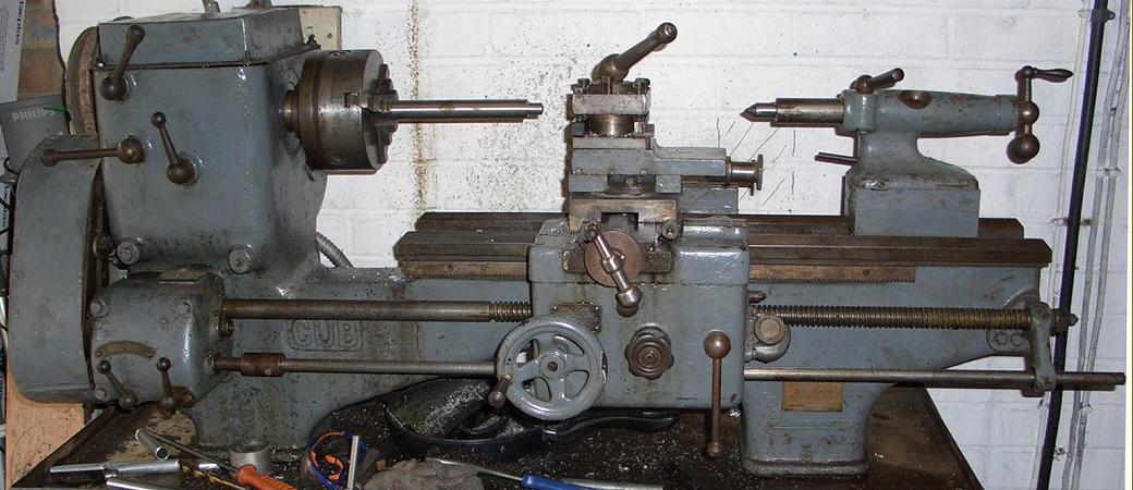
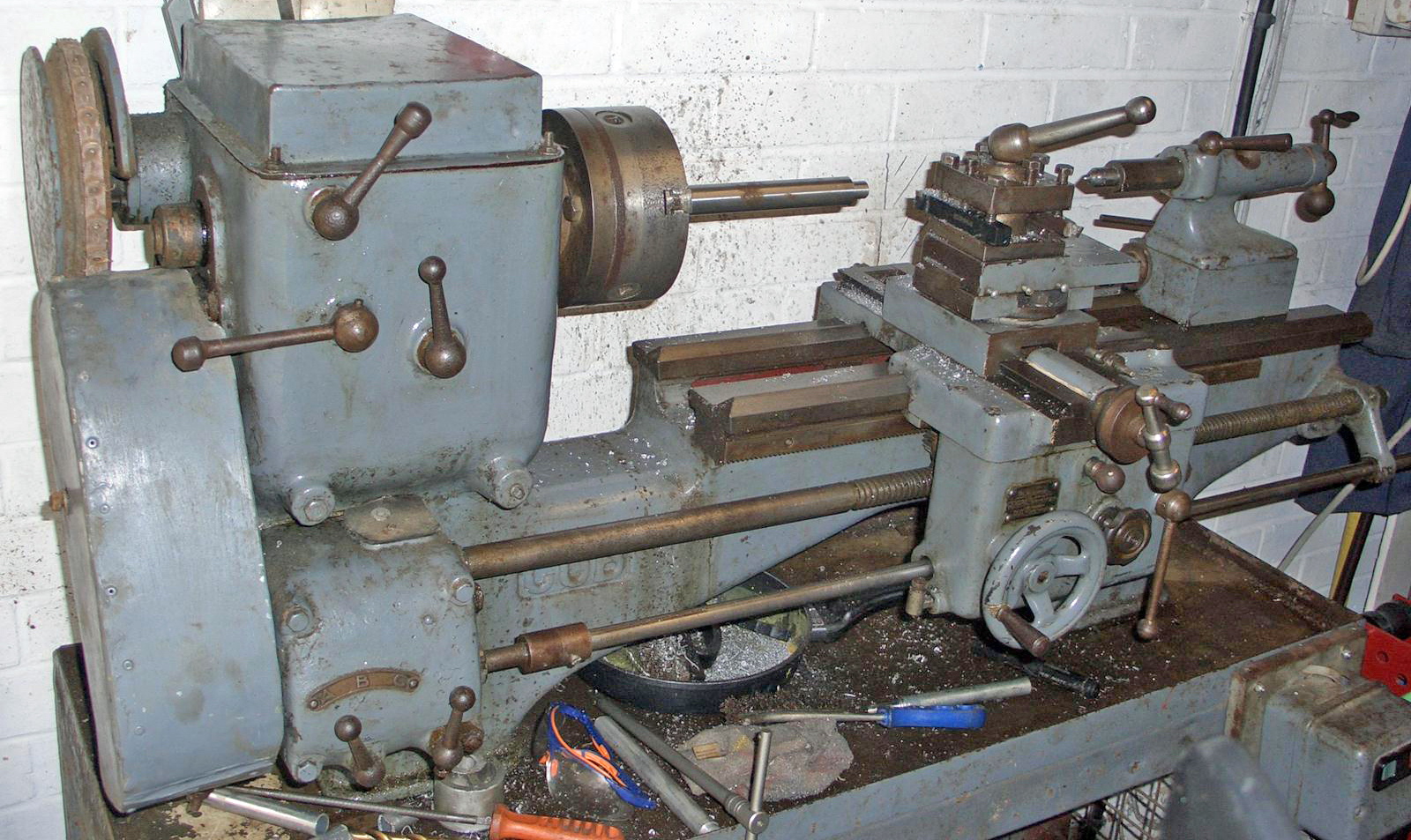
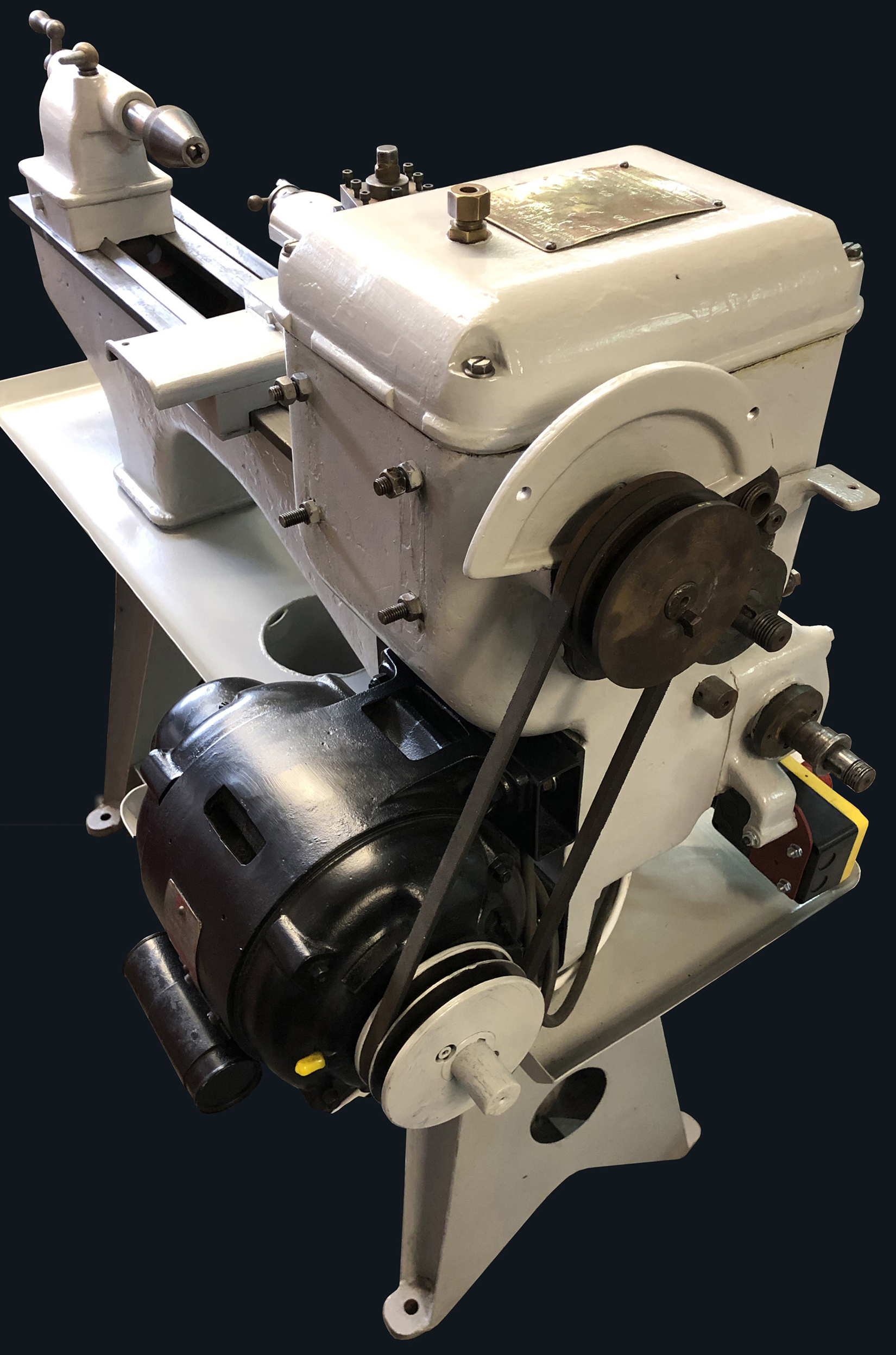
Mk. 1 Churchill Cub with acorn-tipped straight control levers
|
|
|
|
|
|
|
 |
|
|
|
|
|
|
|
|
|
|
 |
|
|
|
|
|
|
|
|
|
 |
|
|
|
|
 |
|
|
|
|
|
 |
|
|
|
|
|
|
|
|
|
|
|
 |
|
|
|
|
|
 |
|
|
|
|
|
 |
|
|
|
|
|
|
|
|
|
|
|
 |
|
|
|
|
|
 |
|
|
|
|
|
 |
|
|
|
|
|
|
|
|
|
|
|
|
|