|
Home Machine Tool Archive Machine-tools Sale & Wanted Page 2 An Operator's Handbook for The Mk. 3 Cub with Spares as detailed sectional drawings is available SOUGHT by the writer: sale or loan of literature for the Mk. 1 & Mk. 2 Churchill Cub Churchill Cub Home Page |
||
|
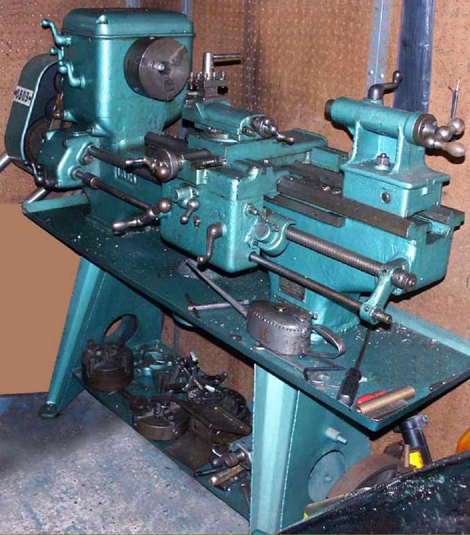
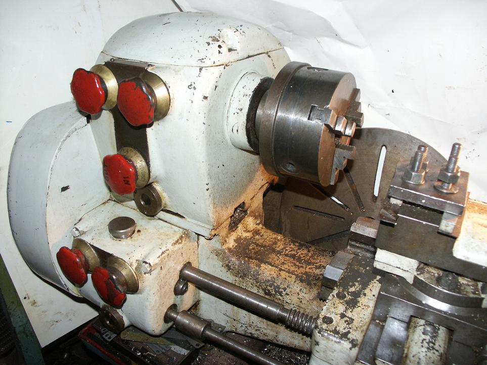
The Mk. 1A Cub was distinguished by a "square" headstock and a number of simple "bent" controls levers. On this model the power feed were both selected and engaged through the action of a single lever on the face of the apron. |
||
|
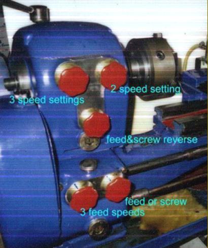
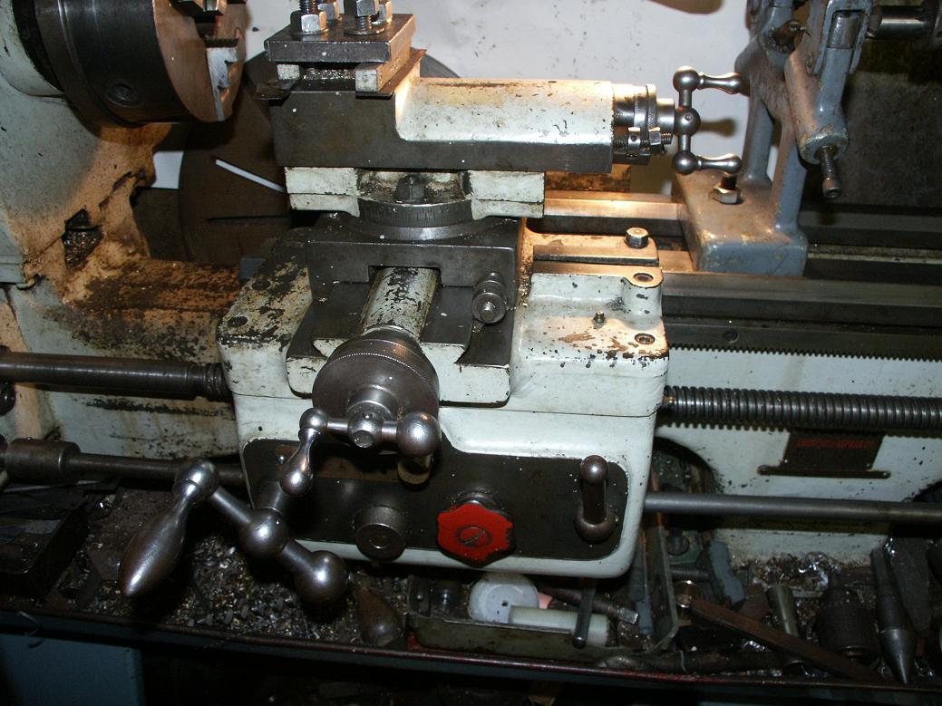
The rounded headstock and dial-type controls of the Mk. 2 Cub |
||
|
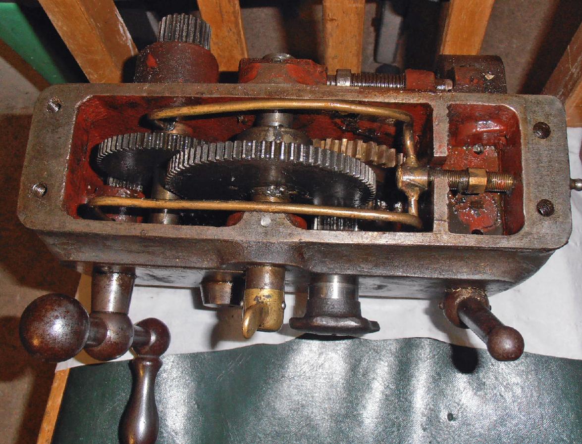
The Mk. 2 Cub had a separate headstock (the Mk. 1's bed and headstock were cast as-one) and was a generally more rounded machine with the lever controls replaced by neatly designed if rather large and smooth-faced full-circle "hexagonal" dials. |
||
|
|
||
|
|
||
|
|
||
|
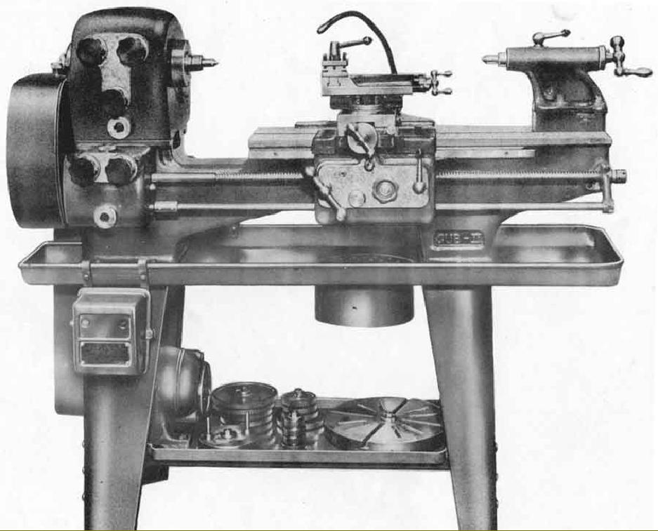
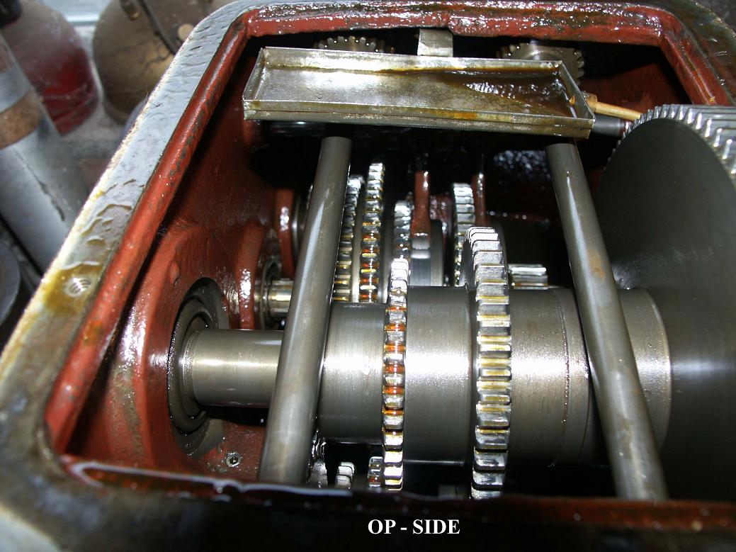
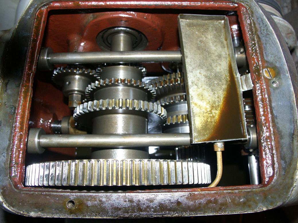
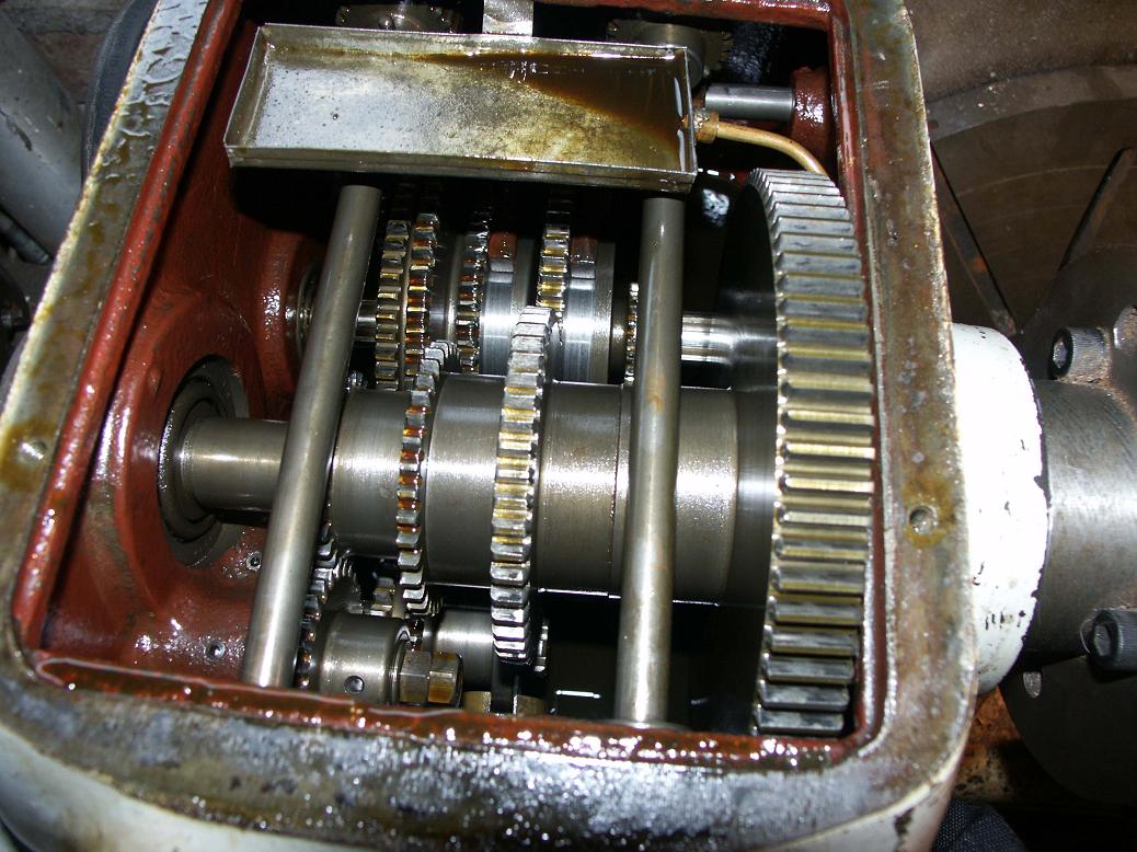
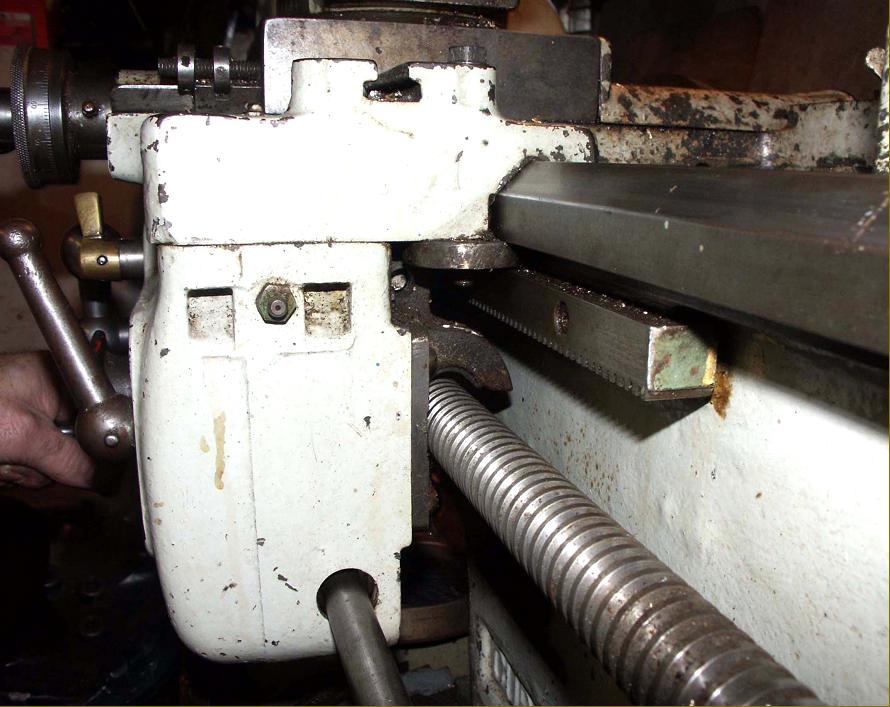
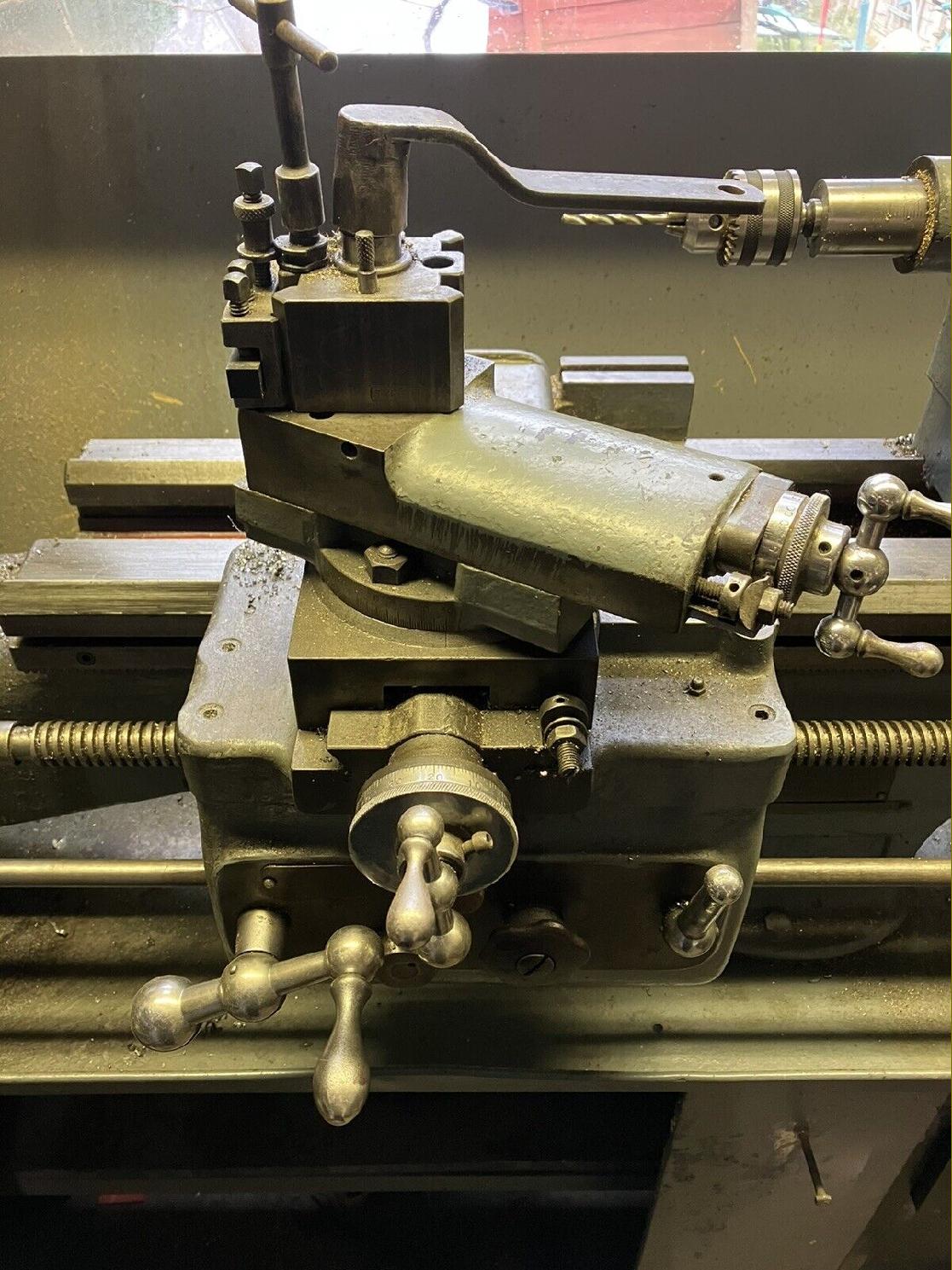
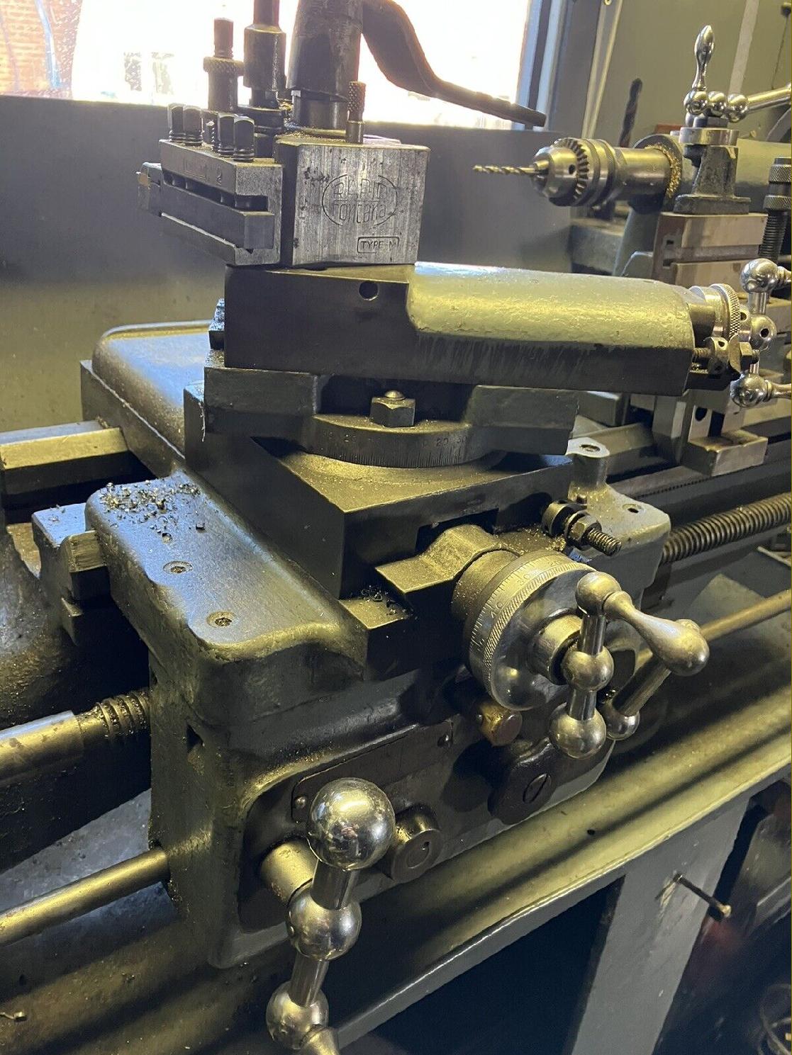
The carriage of the Cub was heavily built with a double-wall apron, exceptionally large micrometer zeroing dials for the period, taper gib strips on both top and cross slides and a completely protected cross-feed screw. Unfortunately the cross slide was of the short type (with a cast cover at the back to cover the end of the feed-screw) and, whilst the power sliding and surfacing feeds were conveniently selected by flicking a centrally-mounted lever left and right their engagement and release was through a screw-in-and-out knob - with no method of reliably and instantly disconnecting the feed. Note the distinctive form of the fixed steady |
|
|
||
|
|
||
|
|
||
|
|
||
|
|
|
|
||
|
|
||
|
|
||
|
Spares as detailed sectional drawings is available SOUGHT by the writer: sale or loan of literature for the Mk. 1 & Mk. 2 Churchill Cub Page 2 Home Machine Tool Archive Machine-tools Sale & Wanted |
||