 |
|
|
|
|
|
|
|
|
|
|
|
|
|
|
|
|
|
|
|
|
|
|
|
|
|
|
|
|
|
|
|
|
|
|
|
|
|
|
|
|
|
|
|
|
|
|
|
|
|
|
|
|
|
|
|
|
|
|
|
|
|
|
|
|
|
|
|
|
|
|
|
|
|
|
|
|
|
|
|
|
|
|
|
|
|
|
|
|
|
|
|
|
|
|
|
|
|
|
|
|
|
|
|
|
|
|
|
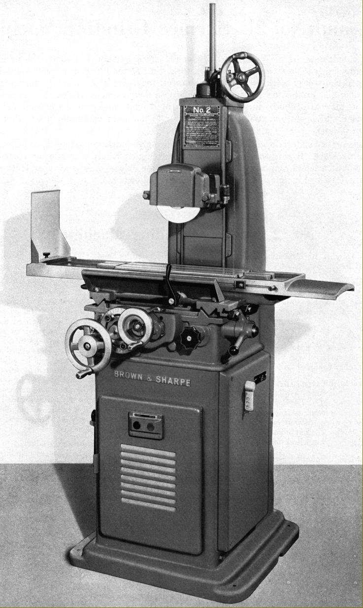
Designed in the 1930s and produced until the late 1940s, the surface grinders listed by Brown & Sharpe as their No. 2 and 2L (mechanical and hand feeds) and 2B and 2LB (hand feeds only) were especially popular models with huge numbers sold world-wide. The ideal machine for the smaller workshop, these robust, reliable and effective machines were of an all-mechanical design - as distinct from models with smooth-running hydraulic table drives as introduced during the 1940s - for example of the S & B No. 5 grinder. Carried on a heavy cast iron base the No. 2 models had a roller-supported table 46" long by 8" wide with a working surface of 18" x 6". With a maximum longitudinal travel of 20", a cross movement of 6.5" and the head raised through 10" to its hugest setting the maximum capacity (using a 7-inch diameter wheel) was a workpiece 18" long by 6" wide and 9.5" thick.
Two spindle drive arrangements were available: one, with the motor in the base, drove both spindle and table mechanism by an endless fabric belt held in tension by the weight of a 1.5 h.p. single-speed motor mounted on a hinged plate in the base of the cabinet; the other used a drive that came direct (through a vibration-damping coupling) from a 1 h.p. single-speed motor mounted on the back of the wheel spindle slide.
Two designs of wheel-carrying spindle were available: one with plain bronze and the other with anti-friction bearings with both, to ease maintenance, being of the removable-unit type. In the plain-bearing version the spindle was hardened and "ground to very close limits of concentricity, straightness and finish." Bearings were in a special bronze, of a tapered design to allow adjustment (which could be set to very fine limits) and lubricated automatically by a built-in rotating pump from a sump within the casing. An external "sight-glass" reservoir of light spindle oil was provided to keep the sump level consistent - the oil being chosen for its ability to produce a low running temperature soon after starting. The rear of the spindle carried a flat belt pulley, the front a taper to mount the wheel-carrying hub. End play could be set without removing the unit, a spring-loaded assembly being provided locked by what the makers described as a "screw clamp that acted as a positive lock.". In the other unit, a sealed-for-life, grease-lubricated, anti-friction spindle assembly, all bearings were of the type classified as being of the super-precision type: pre-loaded roller bearings at front and rear with end thrust in both directions taken out by opposed pre-loaded ball races. As the unit was sealed no additional lubrication or adjustment was necessary, dirt was impossible to get in and, as a consequence, the makers claimed a long and trouble-free life. With no owner maintenance possible, the unit would be returned to the factory when rebuilding was required.
Continued below:
|
|
|
|
|
|
|
|
 |
|
|
|
|
|
|
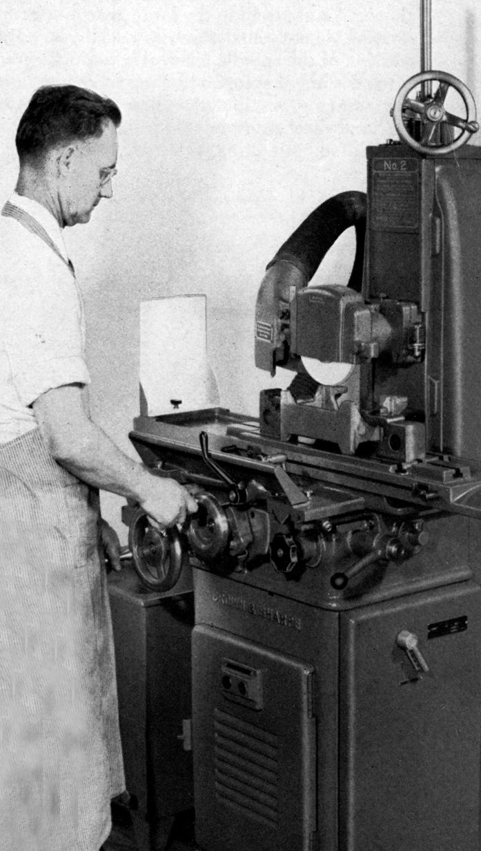
Brown & Sharpe No. 2 surface grinder with hand and power feeds
Continued::
Driven from the base-mounted motor, both spindle types were arranged to run at 3200 r.p.m. (though optionally at 2750 r.p.m. if specified) but when coupled to the direct motor turned at 3450 r.p.m. (with, on this fitting, no option of a slower of faster rate).
As the table drive was all-mechanical, the mechanism employed to produce the automatic reversing left-to-right, right-to-left movements and indexing feeds was a delight to watch in action. Two rates of table travel were available, 19 and 31 feet per minute, selected by a lever behind the longitudinal-feed handwheel. To set the limits of table travel adjustable dogs, carried in a T-slot that ran the full length of the table's front face, caught against a plunger set in the forward part of the manual reversing lever - this plunger able to be withdrawn against a spring to allow, for whatever reason, table movement to go beyond the reversing point but without disturbing the dogs. Set centrally on the saddle, the manual reversing lever was a useful facility when working on very short jobs, just flicking it left and right causing the table to oscillate as required. When operated by hand, one turn of the table's longitudinal handwheel produced a travel of approximately 2" - the wheel able to be disengaged against a spring-plunger for safety reasons when power drive was engaged.
More mechanical delight was to be found in the automatic traverse movement, the limits of its travel being controlled by stop dogs mounted in a T-slot on the saddle's right-hand face. A friction-type arrangement, the automatic cross-feed mechanism could be set to index the feed in, or out, at either or both ends of the table travel - the setting being achieved by two knurled-rim nuts set in partial-circle slots on the face of the unit. Feed rates from 0.01" to 0.09" were available, a large knurled-edge nut in the middle of the assembly being used to engage and disengage the drive; with the mechanism in the latter state the cross-feed could be manually operated without fear of the drive re-engaging.
The spindle head was raised and lowered by a large-diameter handwheel connected to a pair of bevel gears - the horizontal one of which was threaded to take a non-rotating, precision-cut, heat-treated screw. Being of a considerable size, the handwheel rim was used as the micrometer dial, the widely-spaced graduations reading to 0.0005". As an option the makers offered a special fine-feed attachment that allowed the vertical adjustment to be set to just 0.0001" (1/10 of one-thousand of an inch) together with a plunger-type positive stop that could be withdrawn to allow free turning of the wheel . The
Continued below:
|
|
|
|
|
|
|
|
|
|
|
|
|
 |
|
|
|
|
|
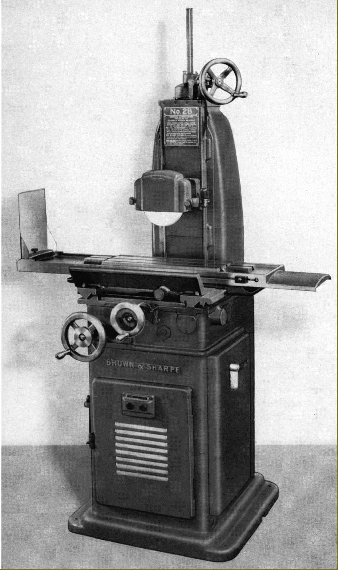
Brown & Sharpe No. 2 B hand-operated surface grinder
Continued:
As well as the regular production models, Brown & Sharpe also offered a number of special and modified types, including ones built to a customer's particular requirements, many of these being detailed with photographs in a factory publication. Such machines and their alterations included a very fine-feed vertical adjustment handwheel, columns made 6" taller, electronically controlled table drives, a high-speed grinding head driven from the main spindle by a right-angle flat-belt drive and with the ability to be tilted 10° in either direction from vertical, powered magnetic chucks with "Neutrol" controls and the rather remarkable "Master Speed" unit that provided (by what appears top have been a swash-plate mechanism) an infinitely-variable speed drive to the table between the rates of 0.75" to 2.25" per minutes
In addition to the accessories supplied as part of the regular equipment (a non-swivel machine vise, wheel truing fixture, a wheel sleeve puller, a straight grinding wheel 7" in diameter, 1/2" thick with a 1.25" hole, a wheel sleeve, a wheel guard and a set of wrenches carried in a holder on the left-hand face of the stand), the makers offered, at extra cost, two magnetic chucks: the No. 510 with a table 5.875" x 10.375 and the No. 6188 with a table 6.375" x 18.125"; a 2.375-inch centre height indexing unit with tailstock - the unit using worm and wheel gearing with the outer face of the wheel drilled with 6 circles of indexing holes allowing all divisions from 2 to 14 and all even numbers from 18 to 28; a self-contained air filter assembly; a wet grinding attachment (both the latter available on a base with castors); a cylindrical grinding and indexing attachment; a high-speed surface grinding attachment; a radius and wheel shaping attachment and a very fine adjustable swivelling machine vise - the latter able to be tilted 45° each side of horizontal, was fitted with 5-inch wide, 1-inch deep jaws in a hardened tool steel that could be opened to a maximum width of 2.75".
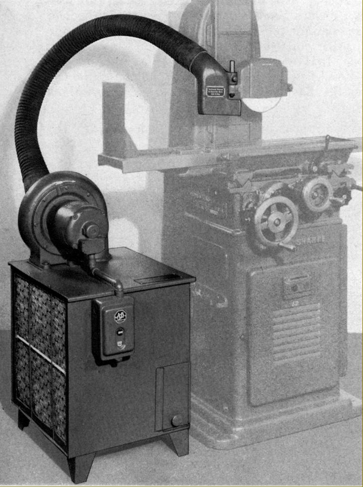
Air Filter Attachment
Fitted with 1/4 h.p. motor-driven fan running at 3600 r.p.m. the air filter accessory drew dust and grid-laden air from around the wheel through a flexible pipe attached to an exhaust nozzle on the side of the wheel guard. As air entered the 24" x 30" x 40" floor-stranding unit it was drawn through a spiral pipe system where centrifugal force caused heavier particles to be thrown against deflectors that directed them into a dust chamber. The air, now free of larger grains, passed into an expansion chamber where the remaining dust (or 99% of it) was spread over the whole area of two viscous-coated, replaceable filter pads.
High-speed Surface Grinding Attachment:
Designed to be used for the grinding of slots and other surfaces where a normal wide wheel would have been impossible, the high-speed attachment used small grinding wheels and drove them at very high speed..
Clamped to the spindle housing in place of the wheel guard, the attachment had a (driven) spindle running in two pairs of super-precision ball bearings and was driven at 18,000 r.p.m. by an endless fabric belt from a pulley mounted on the spindle. Belt tension was adjusted, rather cleverly, by turning a knurled ring on the outer surface of an eccentric sleeve that carried the upper (drive) spindle. A plunger was provided to lock the spindle for wheel changes and lubrication provided by an adjustable drip-feed unit. As the makers recommended the best possible fit between the spindle and wheel holding arbor, they encouraged customers to choose the latter from amongst the set of specially made for the unit.
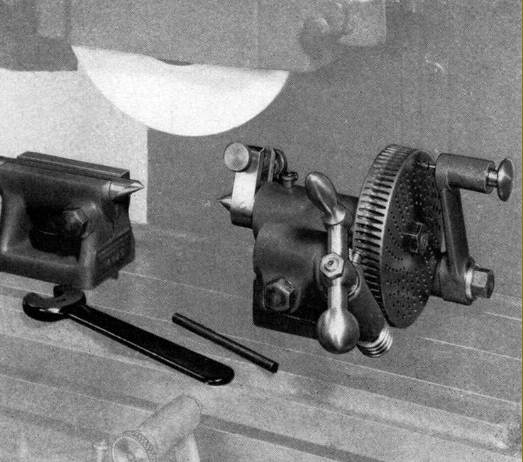
Also listed was a useful little unit, the Cylindrical Grinding and Indexing Attachment
First offered during the 1940s, this was a stand-alone unit intended to be held in place by a magnetic chuck - and hence capable of being mounted on almost any surface grinder.
Measuring 17.3125" long by 7.3" wide and standing 6.4" high, the attachment was able to take a job up to 5.25" long and 3" in diameter. Fitted with a built-in 1/60 h.p. 115 volt motor running at 1725 r.p.m. and a sealed-for-life spindle running in ball bearings, the device allowed work to be mounted between its centres and ground by the surface grinder wheel. In order to multiply the wheel speed for small-diameter work the surface grinder wheel revolved in one direction while that on the unit revolved in the other. Having been ground the unit then allowed the job to be indexed, without backlash (the drive dogs could be adjusted to lock onto the work), so that flats could be ground as required. Should work not ground between centres have need mounting for indexing, a collet chuck with a screwed nose-piece compression ring and a set of 13 dead-length collets from 1/8" to 1/2" in 32nd steps was available in a fitted wooden box. Able to be tilted, the accessory could be used to grind angles on such items as Morse and other centres and double-cone pieces, etc..
|
|
|
|
|
|
|
 |
|
|
|
|
|
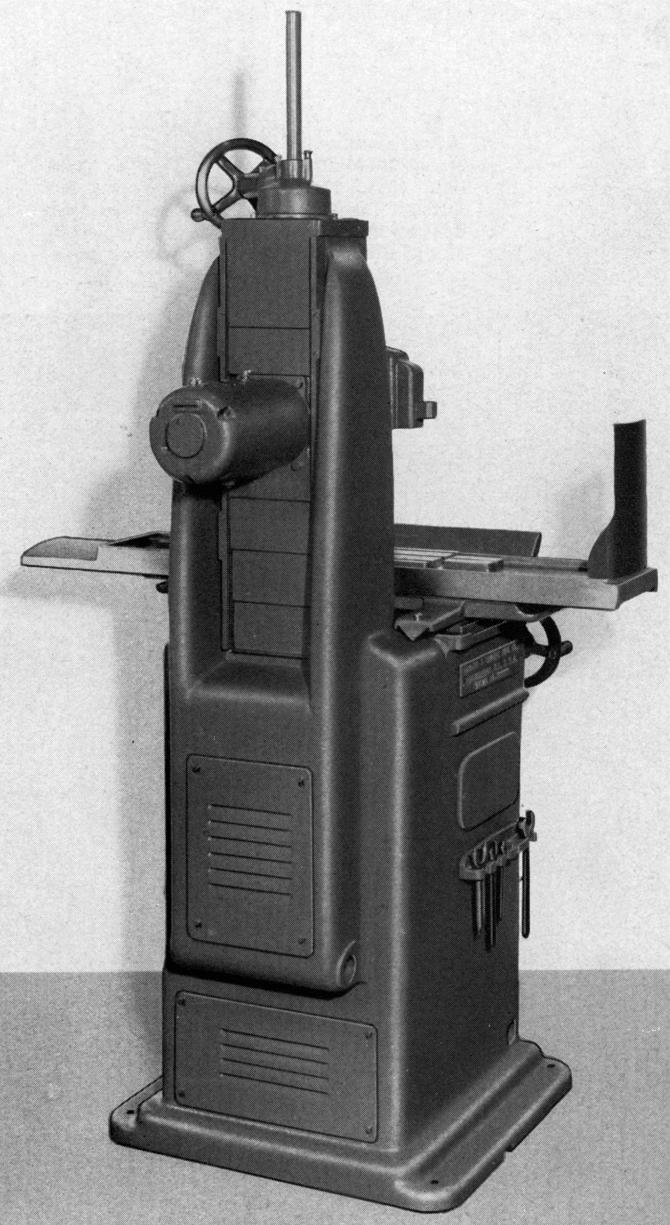
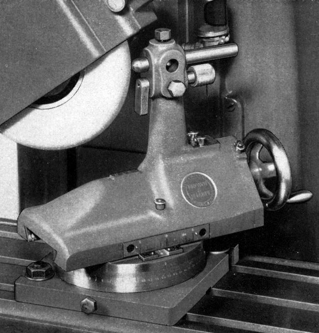
Two spindle drive arrangements were available: one, with the motor in the base, drove both spindle and table mechanism by an endless fabric belt held in tension by the weight of a 1.5 h.p. single-speed motor mounted on a hinged plate in the base of the cabinet; the other (shown above) used a drive that came direct (through a vibration-damping coupling) from a 1 h.p. single-speed motor mounted on the back of the wheel spindle slide. .
|
|
|
|
|
|
|
|
|
|
|
|
 |
|
|
|
|
|
|
|
|
Vibration-damping coupling used on the direct-drive motor
|
|
|
|
|
|
|
|
|
 |
|
|
|
|
|
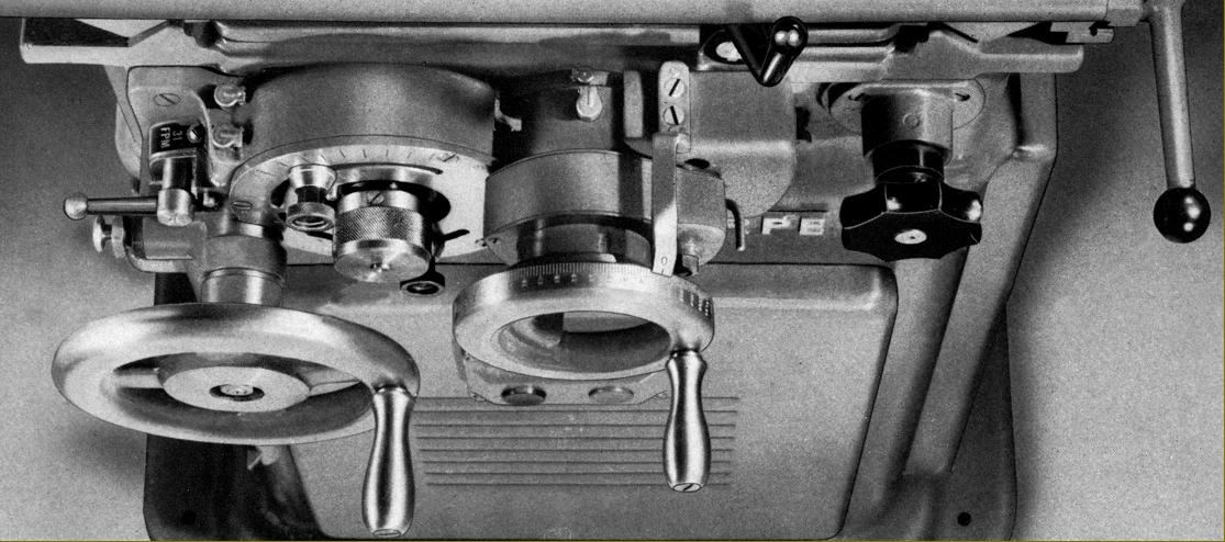
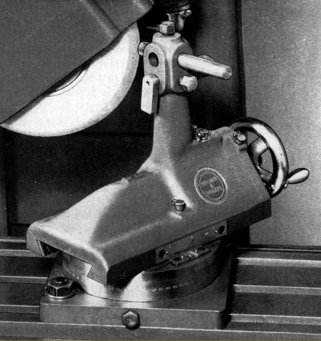
B & S No.. 2 Surface Grinder controls
|
|
|
|
|
|
|
 |
|
|
|
|
|
|
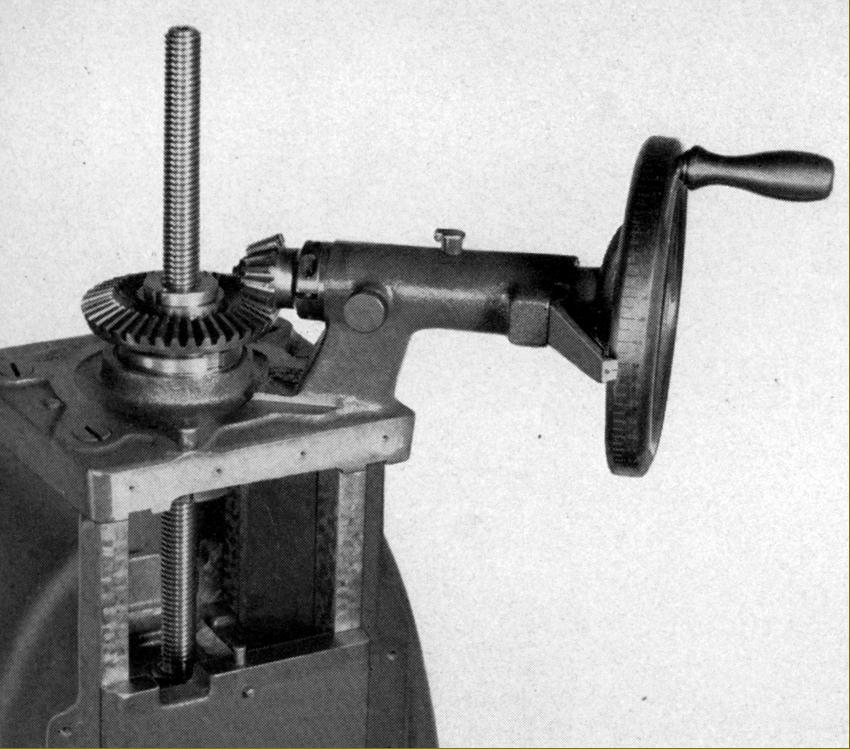
The spindle head was raised and lowered by a large-diameter handwheel connected to a pair of bevel gears - the horizontal one of which was threaded to take a non-rotating, precision-cut, heat-treated screw. Being of a considerable size, the handwheel rim was used as the micrometer dial, the widely-spaced graduations reading to 0.0005".
|
|
|
|
|
|
|
|
|
|
|
|
 |
|
|
|
|
|
|
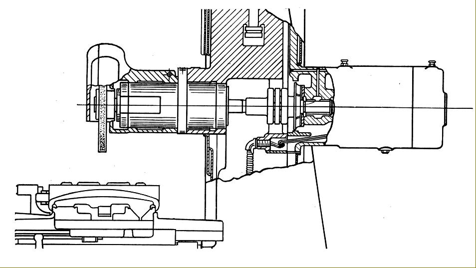
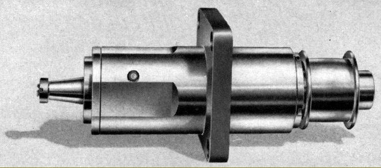
Plain bearing spindle. Bearings were in a special bronze, of a tapered design to allow adjustment (which could be set to very fine limits) and lubricated automatically by a built-in rotating pump from a sump within the casing. An external "sight-glass" oil container was also fitted
|
|
|
|
|
|
|
 |
|
|
|
|
|
|
Sealed-for-life, grease-lubricated, anti-friction spindle assembly. All bearings were of the super-precision type: pre-loaded roller bearings at front and rear with end thrust in both directions taken out by opposed pre-loaded ball races. Sealed, no additional lubrication or adjustment was necessary, dirt was impossible to get in and, as a consequence, the makers claimed a long and trouble-free life.
|
|
|
|
|
|
|
 |
|
|
|
|
|
|
|
|
|
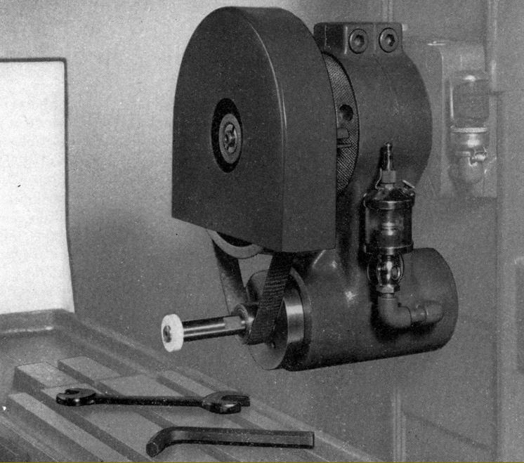
High-speed Surface Grinding Attachment:
Designed to be used for the grinding of slots and other surfaces where a normal wide wheel would have been impossible, the high-speed attachment used small grinding wheels and drove them at very high speed..
Clamped to the spindle housing in place of the wheel guard, the attachment had a (driven) spindle running in two pairs of super-precision ball bearings and was driven at 18,000 r.p.m. by an endless fabric belt from a pulley mounted on the spindle. Belt tension was adjusted, rather cleverly, by turning a knurled ring on the outer surface of an eccentric sleeve that carried the upper (drive) spindle. A plunger was provided to lock the spindle for wheel changes and lubrication provided by an adjustable drip-feed unit. As the makers recommended the best possible fit between the spindle and wheel holding arbor, they encouraged customers to choose the latter from amongst the set of specially made for the unit.
|
|
|
|
|
|
|
|
|
|
|
|
|
|
|
 |
|
|
|
|
|
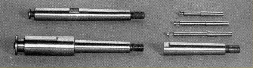
Special high-precision arbors made for the high-speed grinding attachment
|
|
|
|
|
|
|
 |
|
|
|
|
 |
|
|
|
|
 |
|
|
|
|
|
|
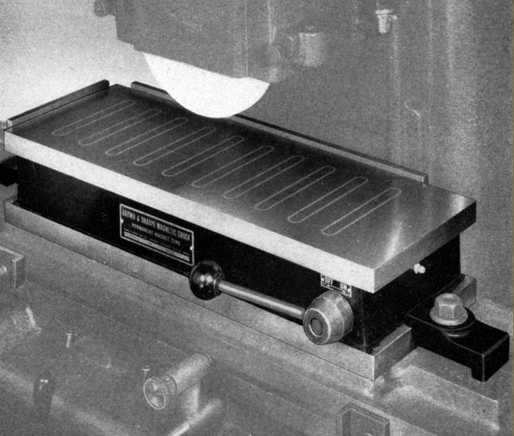
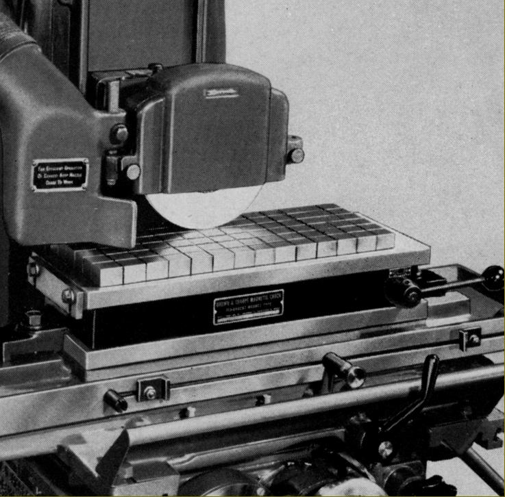
Two magnetic chucks were listed for the No. 2 machines: the No. 510 with a table 5.875" x 10.375 and the No. 6188 with a table 6.375" x 18.125"
|
|
|
|
|
|
|
|
|
|
|
|
 |
|
|
|
|
|
|
A group of identical parts being ground on the magnetic chuck
|
|
|
|
|
|
|
 |
|
|
|
|
|
|
Simple but effective radius and wheel shaping attachment
|
|
|
|
|
|
|
|
|
|
|
|
 |
|
|
|
|
|
|
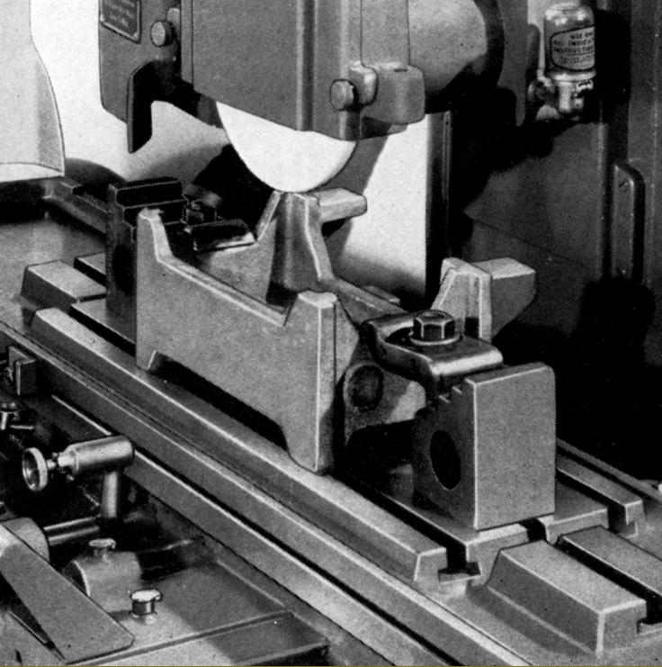
Radius and wheel shaping attachment being used to shape a radial contour. The slide was set by the scale to the required radius and clamped in position by a screw on the opposite side of the slide. The diamond point was set by a tool-setting gauge (shown just below the point) and the slide then swivelled to form the required shape.
|
|
|
|
|
|
|
 |
|
|
|
|
|
|
Radius and wheel shaping attachment being used to form an angle. The swivel base was clamped at the required angle and the slide operated by the handwheel.
|
|
|
|
|
|
|
 |
|
|
|
|
|
|
Air Filter Attachment
Fitted with 1/4 h.p. motor-driven fan running at 3600 r.p.m. the air filter accessory drew dust and grid-laden air from around the wheel through a flexible pipe attached to an exhaust nozzle on the side of the wheel guard. As air entered the 24" x 30" x 40" floor-stranding unit it was drawn through a spiral pipe system where centrifugal force caused heavier particles to be thrown against deflectors that directed them into a dust chamber. The air, now free of larger grains, passed into an expansion chamber where the remaining dust (or 99% of it) was spread over the whole area of two viscous-coated, replaceable filter pads.
|
|
|
|
|
|
|
|
|
|
|
|
 |
|
|
|
|
|
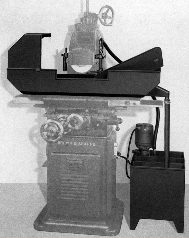
|
Wet grinding attachment with a self-contained, welded sheet-steel tank and a pump unit driven by a 1/4 h.p. motor. Also included was the necessary pipework, distribution head and a large splash guard-cum-coolant tray
|
|
|
|
|
|
|
 |
|
|
|
|
|
|
The very fine adjustable swivelling machine vise able to be tilted 45° each side of horizontal and fitted with 5-inch wide, 1-inch deep jaws in a hardened tool steel that could be opened to a maximum width of 2.75".
|
|
|
|
|
|
|
 |
|
|
|
|
|
|
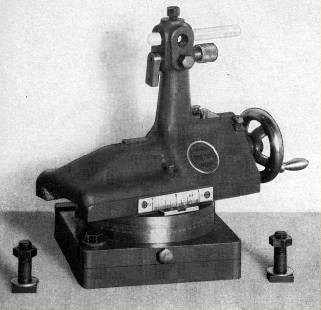
2.375-inch centre height indexing unit with tailstock. The unit used worm and wheel gearing with the outer face of the wheel drilled with 6 circles of indexing holes allowing all divisions from 2 to 14 and all even numbers from 18 to 28. The worm could be disengaged from the wheel and the latter turned by hand. A raising block was available that increased the centre height to 4.125".
|
|
|
|
|
|
|
|
|
|
|
|
|
|