 |
|
|
|
|
|
|
|
|
|
|
|
|
|
|
|
|
|
|
|
|
|
|
|
|
|
|
|
|
|
|
|
|
|
|
|
|
|
|
|
|
|
|
|
|
|
|
|
|
|
|
|
|
|
|
|
|
|
|
|
|
|
|
|
|
|
|
|
|
|
|
|
|
|
|
|
|
|
|
|
|
|
|
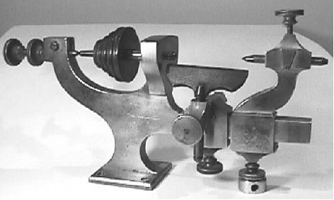
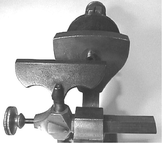
Although the entire illustrated manual for the Bottum wax lathe is reprinted in Theodore Crom's "Horological Shop Tools" (Volume 1, 1980, pages 242-247) this type of early "wax" lathe remains a mystery to many machine-tool enthusiasts. The design and styling was typical of that found on most early watchmakers' lathes with a machined platform holding the rectangular-form frame and headstock - these both being cut from a solid block of brass and secured to each other at right-angles; twin, beautifully knurled rims to the hand grips of the securing screws and a headstock spindle with just a single bearing with its pointed rear end supported in a socket formed on the end of a bar secured within an adjustable housing, an arrangement that also absorbed longitudinal thrust.
The Bottum illustrated is around 10 inches long with its spindle centre approximately 17/8" above the top of the 37/8" long , 1/2" wide and 11/16" deep bed. The 4-step spindle pulley, with brass end plates, is made from wood. Inscribed on the machine is the legend J. M. Bottum New York and underneath (the name) "8 8 8" or "8 8 5". The three US Patents traced for the lathe are:
Patent No 12502 for Watchmakers Lathe dated March 13, 1855
Patent No. 8216 J. M. Bottum, New York, New York Co. Securing pinions and staffs, &c. of watches in lathe or turnbench chucks, 7/15/1851; reissued 7/8/1856, No. 375)
Patent No 24366, June 14, 1859 Measuring Forces of Hairsprings for Watches
Continued below:
|
|
|
|
|
|
|
|
 |
|
|
|
|
|
|
Continued:
This type of lathe was also known as the "Swiss" or "English Mandrel", but these particular machines were usually more advance and with the ability to mount a compound slide rest and sometimes with a simple, hand-operated gear drive to the spindle; although beautifully made, and a delight to behold, the design was quickly made obsolete after the serious development work carried out by Charles Moseley, John Whitcombe and others from around 1859 when Moseley invented the first form of split chuck or "collet" which transformed the usefulness of the miniature lathe - until that point work had to be held by a special heat-softened cement wax, or on expensive 3-clamp "universal faceplate". Subsequent work by these and other engineers resulted in the two quite different "standard" forms of watchmakers' lathe: the heavier American design of WW (Webster-Whitcomb) pattern and the lighter European "Geneva" models, these (and similar types) being built by a multitude of makers notably the German firms of Lorch, G.Boley, Boley& Leinen and Wolf Jahn. Both types were well established by the late 1800s and even today these lathes continue to be manufactured in the form of developed WW-pattern machines by the USA manufacturers Levin and Derbyshire , and Geneva-pattern lathes by Bergeon in Switzerland.
Parallel with the development of the watchmaker's lathe in the closing decades of the 19th century (and the cause of their development and popularity) was an explosion in the numbers of mass produced watches (led by the USA) which for the first time ever put watches into the breast pockets of ordinary people; when these timepieces went wrong, they needed repairing and the new trade of watch-repair man became established. Unfortunately, the mass-produced parts also became available as spares and it was not long into the 20th century before machine tools in the watch-repair shop were something of an anachronism and used only occasionally to make parts for obsolete models.
Today the wheel has come full circle and, as well as an appreciation of the fine-quality work which went into producing watchmaker's tools, there has been a renaissance in the understanding of properly-engineered timepieces and enthusiasts are now employing these lathes once more to create reproduction or newly-designed watches and clocks from raw materials..
|
|
|
|
|
|
|
|
 |
|
|
|
|
|
|
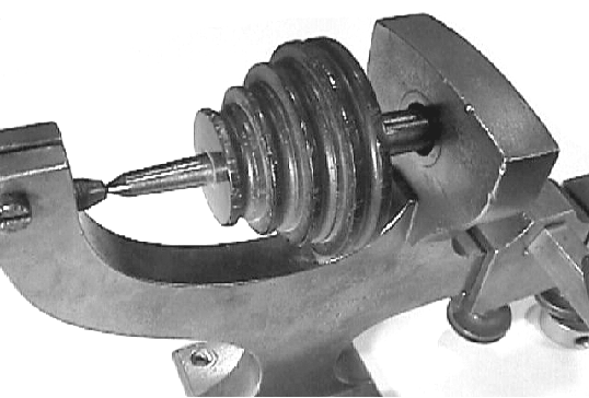
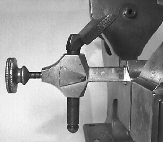
The headstock spindle ran in a single bearing at the front with its pointed rear supported in a socket formed on the end of a bar secured within an adjustable housing.
|
|
|
|
|
|
|
|
|
|
|
|
|
|
|
|
|
 |
|
|
|
|
|
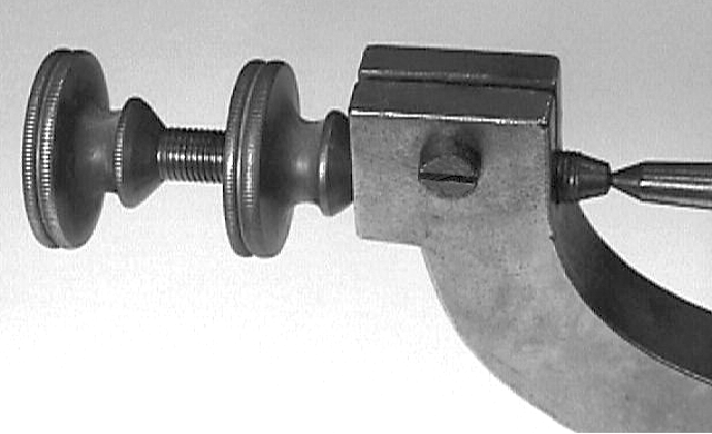
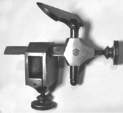
The simple arrangement of the spindle and thrust adjustment on the Bottum
|
|
|
|
|
|
|
|
|
|
|
 |
|
|
|
|
|
|
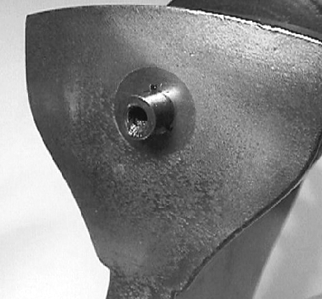
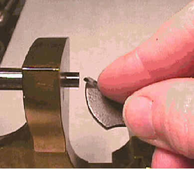
The end of the spindle was formed with a hollow into which was melted a special cement to hold the workpiece. As the cement dried the spindle was run and light pressure applied against the object so causing it to run centrally.
|
|
|
|
|
|
|
|
|
|
|
 |
|
|
|
|
|
|
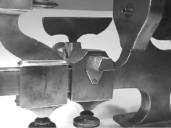
Elegant simplicity. The trapezium-shaped socket in the cross slide was fitted with a loose plate that, under pressure from the screw below, tightened against the cross bar. The pressure plate was prevented from coming out by screw-on retainers front and rear.
|
|
|
|
|
|
|
|
|
|
|
 |
|
|
|
|
|
|
The "slide" assembly removed from the lathe. The screwed-on plate at the bottom of the rectangular socket retains the loose pressure plate within.
|
|
|
|
|
|
|
|
|
|
|
 |
|
|
|
|
|
|
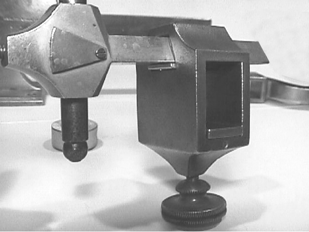
The "cross slide" withdrawn to accommodate the larger of the two T rests
|
|
|
|
|
|
|
|
|
|
|
 |
|
|
|
|
|
 |
|
|
|
|
|
 |
|
|
|
|
|
|
How the lathe was use - a graver pressed against the T rest prepares to take a cut.
|
|
|
|
|
|
|
|
|
|
|
|
|
|
|
|
|
|
|