 |
|
|
|
|
|
|
|
|
|
|
|
|
|
|
|
|
|
|
|
|
|
|
|
|
|
|
|
|
|
|
|
|
|
|
|
|
|
|
|
|
|
|
|
|
|
|
|
|
|
|
|
|
|
|
|
|
|
|
|
|
|
|
|
|
|
|
|
|
|
|
|
|
|
|
|
|
|
|
|
|
|
|
|
|
|
|
|
|
|
|
|
|
|
|
|
|
|
|
|
|
|
|
|
|
|
|
|
|
Developed from a late 1880s design by Wolf Jahn, the Model "WJA", the "B.C.A." precision miller and jig driller inherited all the German Company's precision standards. In addition to the "WJA", Wolf Jahn was, of course, famous for their high-quality watchmakers' lathes and associated tooling. The concept of the machine - a swan-necked column carrying a slide-mounted head above a compound table topped with a rotary table - was then taken up by Leinen, another German maker of precision watch-making equipment, who, by the late 1920s, had developed the machine as their Model "80" or, with a plain compound table, as the "80a". Although these were smaller machines than later versions - the table was only 6-inches (150 mm) in diameter, the hole through the spindle 0.314-inch (8 mm) and the distance from column's inner face to spindle centre just 5 inches (130 mm) - it was now in a form clearly recognisable as the immediate forbear of the later English-made Ultra, Excel and B.C.A. versions. During the 1930s, further improvements were made by Leinen, including the use of heavier castings and a head that could be inclined and driven by a feed-screw; this version also being advertised, simultaneously, as the Leinen, Boley & Leinen and "BFL". Sales catalogues for the brands were identical (but for the name on their cover pages) though the Boley part of the name should not be confused with G.Boley, an entirely separate company. Appearing to have a slightly heavier overall built, the G. Boley had much larger micrometer dials on the compound and rotary tables - while the latter had its "wheel" guarded by a neat sheet-steel cover, a feature lacking on the equivalent Leinen.
Because this was a unique machine, capable of being adapted to a wide variety of tasks and able to work with great accuracy, it is likely that just before (or in the opening months of) WW2, the British Government's Machine Tool Control Rationalisation Board ordered that copies be made for use in instrument factories and other precision and repair facilities. These versions were sold badged first as "Ultra" and "Excel" and then, later, as "B.C.A." (the latter to become familiar as the "B.C.A. Mk. 2"). All the early UK-made machines appear to have been (apart from the much-improved "swing" motor mount and a covered circumferential gear on the rotary table) indistinguishable from the Leinen and the Boley versions of the late 1930s.
Exactly what arrangements were made for the production and marketing of the early British models is unknown, but advertising literature of the time clearly states that the "Ultra" and "Excel" versions were made by one or more of the companies within the then large B.Elliott Group. The maker was probably the Victoria Machine Tool Company (well-known for their milling machines) or, perhaps, the Progress Drilling Machine Works, both of whom would have had the necessary expertise. However, even this is not certain, for it was also stated in contemporary Elliott catalogues that their machines were made: "… at the works of our subsidiary and associated companies whose whole output of machine tools and equipment is solely controlled by us." The clue lies in the word associated, for Elliot had enough buying power to commission, and then re-brand, machines from a several independent UK makers. The miller was also listed in the sales catalogues of the well-known machine-tool marketing company E. H. Jones, where it appeared first with "Sigma-Jones", then Excel and finally B.C.A. badges. The first of those three names is interesting, for part of the giant Herbert machinery group was a specialised engineering company acquired in 1947, Sigma Instrument Co. Ltd. (based on a 2.5-acre site in Letchworth), who manufactured a wide range of high-precision test and inspection equipment including, from a 1947 Olympia Exhibition catalogue: Mechanical, Electrical, Optical and Pneumatic Comparators; Automatic Inspection Equipment. Gas Testing Equipment including Recording and Indicating Calorimeters, Specific Gravity and Pressure Recorders, etc. Hence, with their considerable expertise, producing a small jig borer would have been a relatively straightforward undertaking for this company. Used by Elliott from the 1930s until the 1960s, the Excel brand was a marketing name used to promote specialised tool and jig millers, small jig borers, precision filing & sawing machines, tool & cutter and surface grinders and other items - the Excel name indicating that the various products would be of better-than-average quality and usually directed towards a specialised segment of the market.
By now well established, the design of the jig borer passed to B.C.A. (Bloctube Controls) of Aylesbury, Buckinghamshire, a firm whose main activity centred around mechanical control systems for aircraft flight-surfaces and other items requiring small, precisely-manufactured and ultra-reliable parts. Bloctube is still going strong as Bloctube Marine Services Ltd. who concentrate on ships' equipment and other specialised items including an interesting and very clever remote-controlled twin-beam searchlight - a unit able to turn non-stop with simultaneous 360-degree movements in both vertical and horizontal planes. By the mid-1950s R. E. Godfrey Ltd. of King's Mill, Kings Mill Lane, South Nutfield, Redhill, Surrey had taken over rights and built the machine in collaboration with the Kine Engineering Works, also in Redhill (this company were also involved with Multico in the manufacture of woodworking machinery and other sub-contract work). The BCA was always an expensive proposition and, ain 1958 was priced at £256 (when a Myford Super 7 was around £90), the advertising literature using the description: The Junior B.C.A Jig Boring Machine - possibly to distinguish it from the soon-to-be-announced Mk. 3, a much heavier and more robust model introduced under Godfrey's ownership. By 1962 the price had risen by over 40% to £360 - the Super 7 now being only some 13% more at £102. Rights to the BCA then passed to the present makers, Tenga Engineering, of Redhill, Surrey
During the 1960s and 1970s, R.E. Godfrey was also responsible for the B.C.A. Optical Jig Borer, a much larger (but still relatively small), floor-standing machine that must have been made, judging by the few encountered today, in very limited numbers).
Continued below:
|
|
|
|
|
|
|
|
|
|
|
|
|
|
 |
|
|
|
|
|
|
|
|
|
Excel Model "0" Jig Boring Machine. The "Ultra" and B.C.A. Mk. 2 versions
were almost identical with many interchangeable parts
Continued:
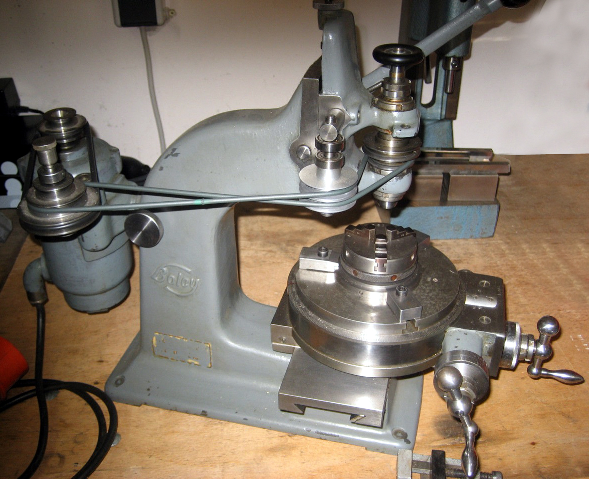
Although all early examples of the machine appeared superficially identical, various improvements were made as UK production got underway, with some machines having 6-inches of clearance beneath the spindle nose and others 7; speeds also varied with those on the "Ultra", for example, becoming 365 to 1045 r.p.m whilst the Excel had a range that extended from 565 to 1560 r.p.m. Another version was also built, presumably for some special-purpose task, with the motor spindle carrying a reduction gearbox that gave a maximum speed of only 500 r.p.m. - a figure so low as to render it completely unsuitable for use with small-diameter cutters. However, probably the most significant improvement was to the head where, instead of being limited to 40-degrees of inclination each side of vertical, an increase was made to a more useful 45-degrees - with precise location back to zero assured by the use of a ground dowel pin. Although the changes to the head angle were welcome, the machine was still stuck with a drive system that mitigated against further improvement - a fractional H.P. motor bolted to the back of the column that drove the spindle with a round (originally composite-construction leather and fabric) "rope" via a series of jockey pulleys. After leaving the motor pulley the rope ran first over a jockey pulley mounted on a bar pivoting concentrically with the motor's spindle and tensioned by a heavy tapered cast-iron weight suspended within the main column. The drive then passed around a pair of pulleys carried on an adjustable (spring-loaded) arm mounted on a bracket formed as part of the head casting. Although the various guide pulleys ensured the belt was always wrapped snugly around the spindle pulley, as the head reached its maximum inclination the rest of the assembly struggled to keep the belt in place - and anyway, the boss carrying the jockey pulleys eventually fouled the side of the column. To be blunt, the drive is a thorough nuisance - though one example, an "Ultra" once owned by the writer, a simple yet ingenious solution had been found - the motor was fixed to a plate carried, near its top edge, on a short bar that fitted into a hole on the back of the column; this arrangement allowed the motor to be swung in sympathy with the head and the belts to run almost in line, no matter how far over the head was inclined. In addition, this example was fitted with a very neat light unit, from the navigator's table in a Liberator bomber - but that's another story… Unfortunately, the Ultra drive system was not further developed - indeed, later versions of the machine, built by both B.C.A. and R.E.Godfrey, had heads restricted to just 30 degrees of tilt with the first pair of jockey pulleys carried on an arm that pivoted on a stud that fitted into a boss on the left-hand face of the machine (all these variations can be seen in the illustrations and photographs below). An improved drive system, used on a friend's machine, was to remove the jockey pulleys and use their mounting bracket to hold one of the small but powerful DC Winchester disc drive motors used in old main-frame computers. This particular set-up gave, in conjunction with a variable-speed controller and the 3-step pulley (using a modern poly-cord belt), a speed range that ran from 100 to over 4000 r.p.m. Today, however, a small 3-phase motor under the control of a phase inverter would be the way to go.
|
|
|
|
|
|
|
|
|
|
|
|
|
|
|
|
|
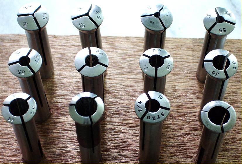
On the original Wolf Jahn "WJA" the head would have been based on one taken from the company's smaller precision bench lathes and held a spindle and bearings made from glass-hard ground steel lapped to a perfect finish and advertised as being capable of "up to 5000 rpm.". On the Boley and subsequent versions the head was a specially-designed unit and contained a 7/16-inch bore spindle made from high-quality steel hardened, ground and running in hand-finished parallel-bore (slotted) phosphor-bronze bushes, threaded at both ends, and set in tapered housings. Serrated ring nuts, that drew the bearings down into their seats, were used for adjustment; however, to limit the extent to which they could be closed, each had a thin bronze insert (that could be thinned if necessary) slipped into their "compression slot". The upper and lower adjustment rings for the top bearing (the smaller of the two), were each extended to hold a large self-aligning SKF ball race designed to absorb the considerable spindle end thrust experienced during boring operations in harder materials. The 3-step cast-iron drive pulley was keyed to the spindle and secured by a single slotted-head screw that bore against the key. On the left-hand side of the head was a screw-adjustable depth stop and most machines also had a simple clamp (to the right of the spindle) to lock the head when taking cuts with the compound or rotary table. The spindle nose was 5.5-inches above the table (minimum distance 2-inches) with cutters and boring heads held in rather small collets of the Lorch "long-series" type. Some of these collets have been found with a thread inside to hold screwed cutters, this arrangement preventing the end mill or similar from "walking out" of a plain collet if used to cut sideways. The feed screw, in hardened steel, ran through a long bronze nut slotted vertically halfway along its length (but without an adjustment screw); play in the slide was adjusted out by either an ordinary "push-screw" gib strip or a thick, tapered gib block that, like the slideways, was hand scraped to a perfect flatness. Although the head carried an engraved ruler scale extending to 5 inches, only 4.5-inches of travel was available.
While just one range of five speeds (565, 700, 935, 1160 and 1560 r.p.m.) had been available on the "Excel", the B.C.A. Mk. 2 offered the choice of two: 350, 470, 590 and 1000 rpm as standard or, at extra cost 700, 940, 1180 and 2000 r.p.m. Although useful for larger-diameter boring work neither range was fast enough to get the best out of very small-diameter cutters and it is not unusual to find machines where owners have fitted a 2800 r.p.m motor, or a larger drive pulley, to obtain significantly higher revolutions.
Using scraped ways, the compound-slide rest had a longitudinal travel of 7 inches and across of 5 inches - though the Elliot sales literature mistakenly claimed 8 inches for each axis of both the "Ultra" and the "Excel". The feed screws were ground from hardened stock and ran though bronze nuts with the simplest form of backlash compensation - a slot cut through the nut with a screw to nip up the clearance. Although the micrometer dials were rather small and lacked vernier scales, they were calibrated in 0.001" increments and each axis was also provided with a ruler fitted into a clamp such that it could be adjusted quickly and easily. Attachment points to hold dial-indicators were also fitted, as were screw-adjustable stops - though, unaccountably, some machines have been found without either of the latter two refinements. Instead of a conventional T-slotted rectangular table the top section of the compound slide was formed as a permanent 8-inch diameter rotary table, engraved at 2-minute intervals and with 3 (later 4) T-slots. The table worm-drive gear was contained in a rectangular housing at the front (on the German versions this was rounded off) that could be disengaged by slackening two cross-pin-headed screws, so allowing it to be spun by hand. Occasionally machines are found with a rectangular T-slotted slide on top of the rotary table (which severely restricts the height of jobs that can be accommodated) or (even more unusually) a rectangular table in place of the round.
The final development of the borer, which attempted to address the remaining shortcomings of the Mk. 2 and make it into a truly useful machine, was the B.C.A. Mk. 3. Of significantly more massive construction, with a much deeper and wider main column, this version was arranged to carry the head higher and so give both an extra 2 inches of clearance between spindle nose and table and a vertical travel of a little over 6 inches. The head castings were heavier, with slightly wider slides (though the spindle and bearings remained unaltered) while on most examples made, both a direct-acting screw and a side-mounted handwheel were fitted, the latter driving (at 90-degrees) through worm-and-wheel gearing to give an extra-fine feed. Both elements of the compound table were lengthened to give an extra two inches of travel on each axis and the feed screws equipped with ball thrust races and larger micrometer dials. The number of slots in the 8-inch rotary table was increased to four and, by using a 2-speed 3-phase motor, 11 spindle speeds were available spanning 300 to 3250 rpm, a significant improvement on the limited and comparatively slow ranges available previously. The drive system was also modified and, instead of a tensioning weight within the column, an extra pair of jockey pulleys was used, mounted on a swinging bracket pivoting on a bar socketed into the left-hand side of the column. Unfortunately, the modifications to the drive resulted in the head's maximum inclination being reduced from 40° or 45° to only 30°
Installed in a modeller's or experimenter's workshop, any type of B.C.A. is probably the ultimate in a compact, versatile precision milling machine; the built-in 8" rotary table means that complex jobs can be set up and left in place through multiple machining operations, while the ruler and dial-indicator mounts mean a quick and easy way of checking lengths and depths of cut. The continuing usefulness of the machine is demonstrated by the fact that the Mk. 3 remained in production until the 21st century with late examples finished in a rather pleasing, smooth black finish - though the price of over £10,000 (in 2000) while not so attractive, did reflect both the great care taken in its construction and the use of good quality materials. BCA continued here.
Tony Griffiths..
|
|
|
|
|
|
|
|
|
|
|
|
|
|
 |
|
|
|
|
|
|
The pre-WW2 Leinen (and Boley & Leinen) Type BFL. The specification was almost identical to that of the English Sigma with a 7/16" hole through the spindle, a maximum clearance between head and table of 5.5", a distance from column to spindle centre of 8", a maximum head inclination of 40° or 45° and an 8-inch diameter rotary table. A careful examination of the picture will reveal a wire, connected to head-balance weight inside the column and the motor-mounted jockey pulley used to tension the drive belt.
|
|
|
|
|
|
|
|
 |
|
|
|
|
|
|
Boley & Leinen Model 80 of the 1920s. This was a smaller machine than the later models with a 6-inch (150 mm) rotary table, a 0.314-inch (8 mm) hole though the spindle, a distance from column to spindle centre of 5" (130 mm) and a weight-balanced lever-feed head that could not be inclined.
|
|
|
|
|
|
|
|
|
|
|
 |
|
|
|
|
|
|
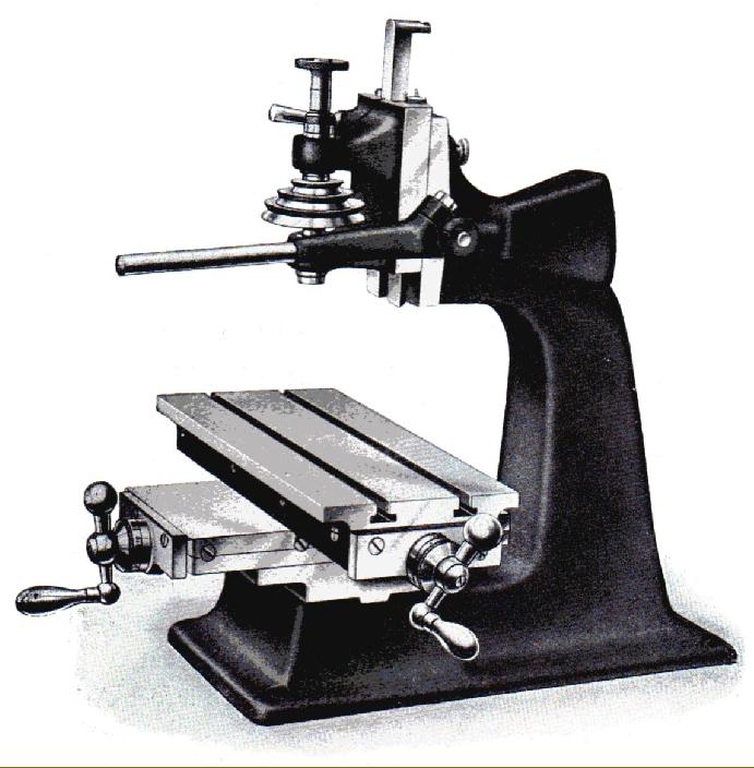
Above, and in the photograph immediately below, the original version of the machine type as produced from the late 1800s to the late 1920s (in various forms) by the German Wolf-Jahn Company. This model, the WJA, not only had a screw feed to the head, but a lever feed as well. The head was an adaptation of those used on the company's watchmakers' lathes and held a spindle and bearings made from glass-hard ground steel lapped to a perfect finish - they were advertised as being capable of "up to 5000 rpm."
Although not clear from the engraving, the column of the machine was in two parts, allowing the insertion of a distance piece to increase the clearance between the spindle nose and the 4.75-inch diameter rotary table. More details can be found here.
|
|
|
|
|
|
|
|
|
|
|
|
|
|
 |
|
|
|
|
|
|
Boley & Leinen 80a with plain compound table
|
|
|
|
|
|
|
|
 |
|
|
|
|
|
 |
|
|
|
|
|
|
Although "Leinen" were also registered as "Boley & Leinen" they had no connection with "G. Boley" Company. However, G.Boley did make their own version, a model far less frequently encountered than the pre-WW2 Leinen (and Boley & Leinen) Type BFL. The G. Boley appears to have had a slightly heavier overall built with the compound and rotary tables equipped with much larger micrometer dials. The "wheel", cut into the periphery of the rotary table was also fitted with a neat sheet-steel cover - a feature lacking on the equivalent Leinen model
|
|
|
|
|
|
|
|
|
|
|
|
|
|
 |
|
|
|
|
 |
|
|
|
|
|
|
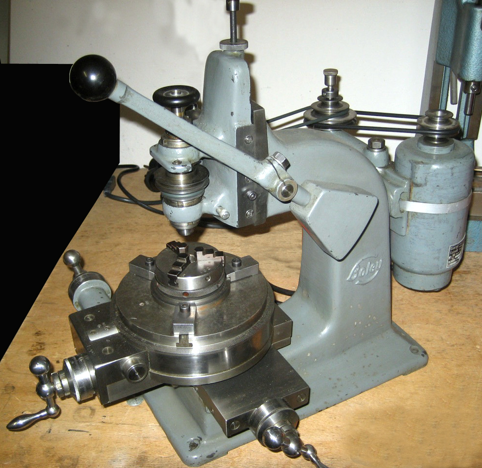
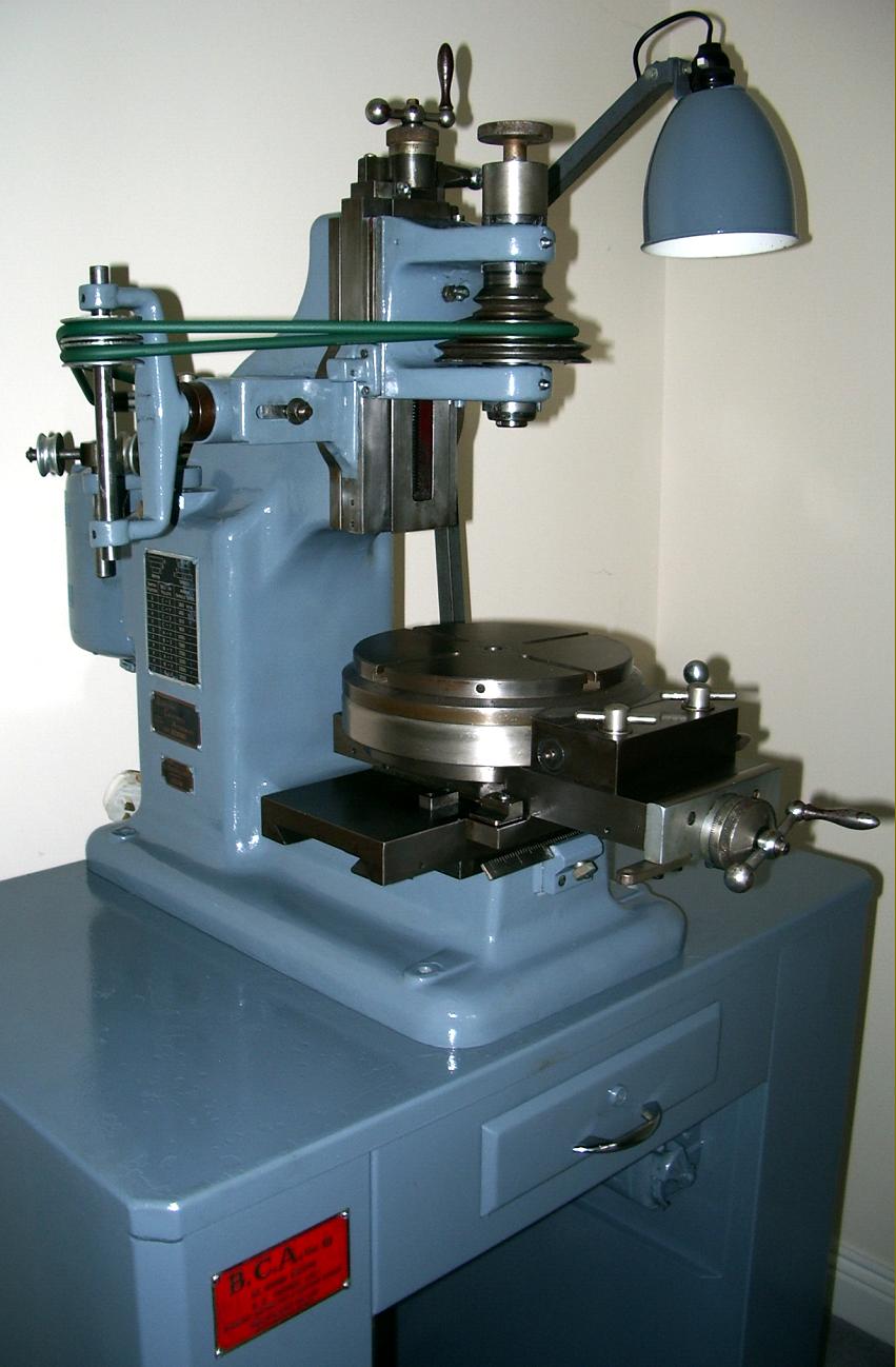
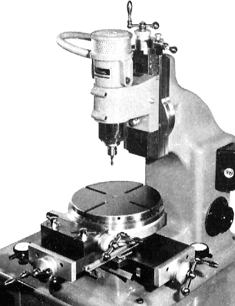
BCA Precision Milling and Jig Driller Machine Mk. 2
Identical to the earlier Excel and Ultra versions (apart from slightly larger handwheels)
this example has a gearbox on the end of the motor to give reduced speeds. It is a relatively easy job to remove this, and reposition the motor, if higher revolutions are needed.
|
|
|
|
|
|
|
|
|
|
|
|
|
|
 |
|
|
|
|
|
|
"Lorch long collets" as made by Crawford for the BCA
|
|
|
|
|
|
|
|
 |
|
|
|
|
|
|
|
|
|
|
|
 |
|
|
|
|
|
|
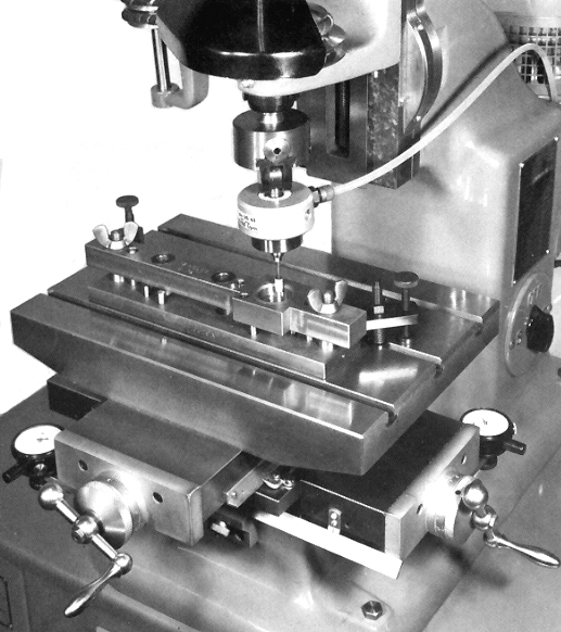
Mk 3 fitted with the optional rectangular table and air-powered jig-grinding unit on a
|
|
|
|
|
|
|
|
|
|
|
 |
|
|
|
|
|
|
Mk. 3 BCA with Digital Positioning Read Out
|
|
|
|
|
|
|
|
|
|
|
 |
|
|
|
|
|
|
High-speed head - a special, very rare unit capable of running up to 60,000 rpm.
|
|
|
|
|
|
|
|
|
|
|
|
|
|
|
|