|
Home Machine Tool Archive Machine-tools Sale & Wanted Barnes Twin Leadscrew Lathe Barnes Twin Leadscrew Lathe Page 2 Barnes Home Page |
|
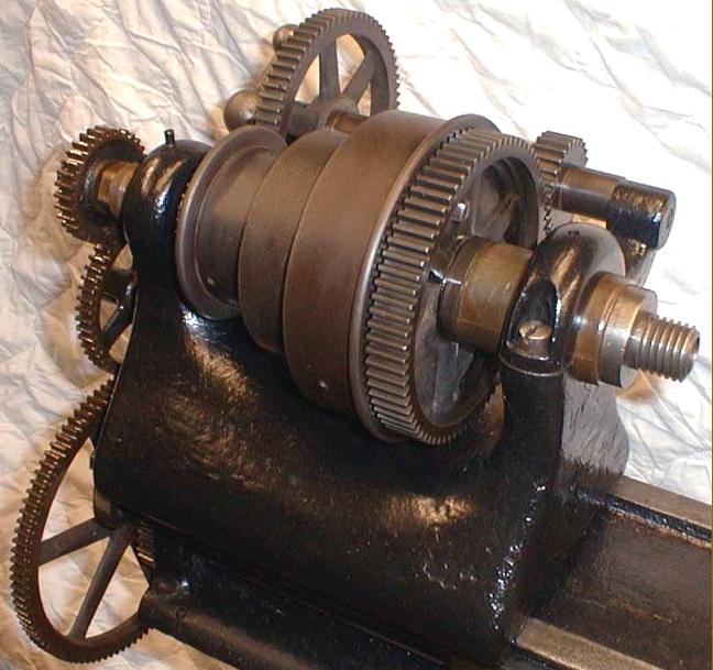
A design used until the 1920s, the Barnes twin-leadscrew lathe was an unusual creation, having several features which flew both in the face of accepted practice and common sense. The idea of using two leadscrews to provide a quick method of reversing the feed to the carriage was not a Barnes invention, but they were one of very few manufacturers to incorporate the idea into a modestly-priced lathe. The drive was very simple; a gear on the end of each (identical) leadscrew meshed together so as to cause each to revolve in the opposite direction. A block, fastened to the apron, contained two clasp nuts under the control of one lever; by simply moving the lever up and down the direction of travel of the carriage could be instantly started, stopped or reversed. In later years, Barnes realised that if the two leadscrews were properly "synchronised" it was possible for the operator to flick from the engagement of one leadscrew to the other--and so run a tool forwards and backwards while generating thread - or using the power sliding feed. Apparently some lathes can be found with marks on their changewheels to indicate that the leadscrew will be in synch. |
|
|
||
|
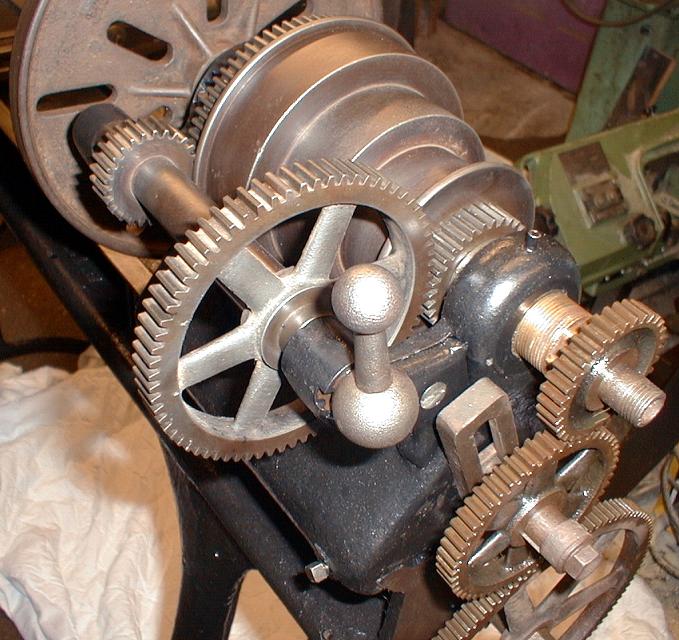
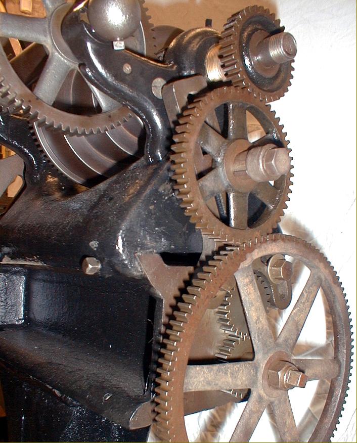
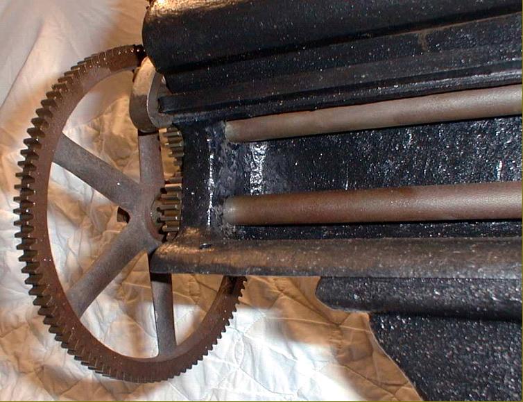
The keyed changewheel stud (of the middle gear) shows that the drive could originally have been "compounded" - with both a large and small gear keyed together on each of two pins - to provide a finer feed to the leadscrews. The headstock was held to the bed by just two square-headed bolts bearing against the rear Vee. |
||
|
|
||
|
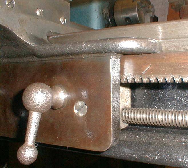
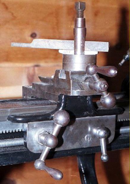
The single lever on the apron of the "twin-leadscrew" was turned through 180 degrees to engage right and left-hand feeds. Note the original cross-head screws on both the cross-slide gib-strip adjustment and rack. Amazingly, the saddle ignores the top front way of the bed completely and runs instead on a cast-in "shelf" (against the lower edge of which the rack registered) and just the lower part of the bed's outer Vee. |
||
|
|
||
|
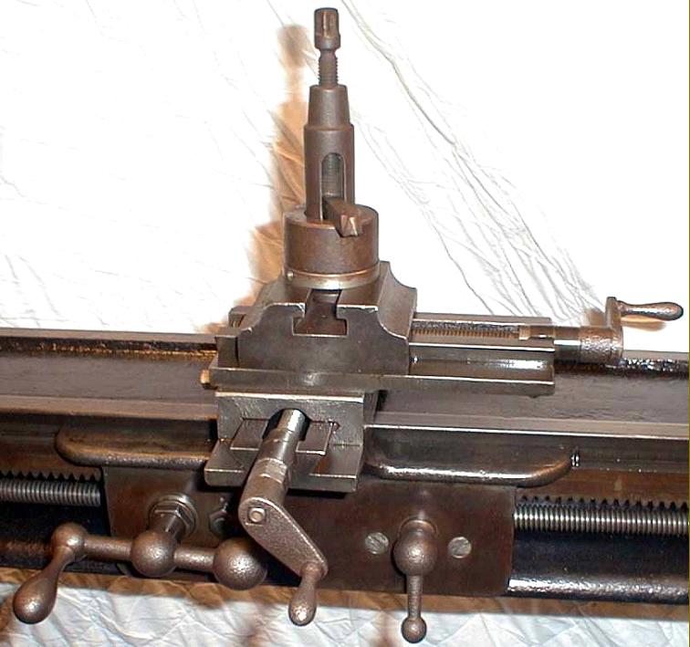
Carriage assembly: there were no graduations on the feed screws which were "wrong-handed" - turning the handles clockwise resulted in the slides moving backwards rather than forwards. |
||
|
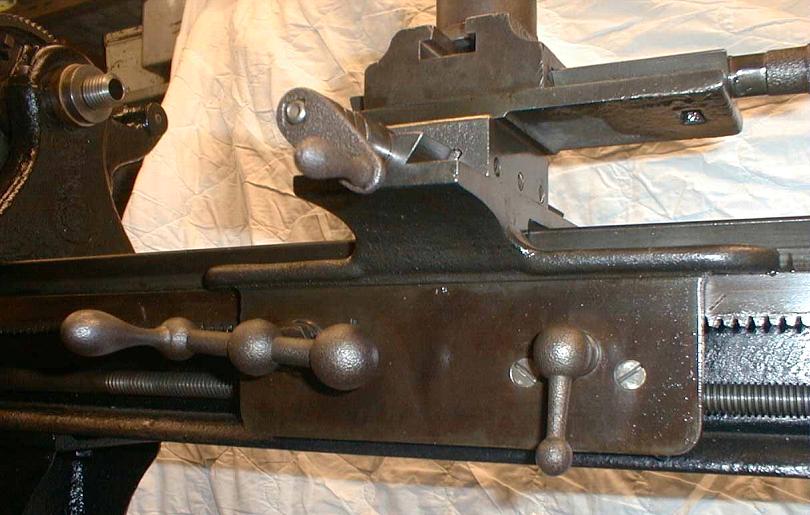
The saddle - cast in one piece with the apron - provides an interesting contrast with contemporary designs; the rear part, instead of being long enough to share with the front the job of providing a solid base from which the tool could do its work, was made very short, as through the designer considered the various forces would only resolve themselves on the front shear. However, having shifted his attention to the front he decided to let the saddle curve over the front top "way" of the bed and make it run on the lower part of the bed's outer Vee and the narrow top of a cast-in shelf immediately above the rack. The single bolt protruding from the face of the cross slide was used to release the top slide so that it could be swivelled. |
||
|
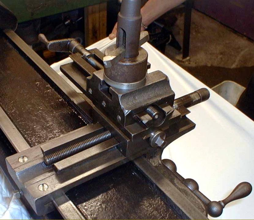
Saddle and Apron were cast as one piece. Note that the saddle is resting on top of a narrow shelf, immediately above the rack, and bearing against only the lower portion of the bed edge. |
||
|
Home Machine Tool Archive Machine-tools Sale & Wanted |