email: tony@lathes.co.uk
Home   Machine Tool Archive   Machine-tools Sale & Wanted
Machine Tool Manuals   Catalogues   Belts   Books  Accessories

Elliot Cardiff Major, Senior, Prefect, Crusader,
Omnispeed, Omnitool & Omniturn Lathes

Omnispeed, Omnitool & Omniturn Lathes

Elliott Milling Machines

Handbooks and Parts Lists
are available for most Elliott machine tools


From the 1940s to the late 1970s the Elliott Machine Tool Group made and marketed a number of different lathes - including late, angular-styled imported versions badged Omnispeed, Omnitool and Omniturn, these lathes also being braned as by Butler, then a compnay owned by the Elliott Group. Of the earlier models, the most popular seem to have been the 7", 7.5" and 8" centre height Major, 8.5" Senior, 9" Prefect and the 11" Crusader, all produced by an Elliott manufacturing subsidiary, the "Cardiff Lathe and Tool Works" with a factory in Taffs Well, a village six miles north west of Cardiff city centre. Constructed during WW2 as the "Patons Works" for the manufacture of ammunition, the building still stood in 2010 painted white but with the original green beginning to re-emerge. The chief designer during the 1950s was Charlie Robinson who, like many of his kind, had been trained at Herbert, in Birmingham. Until about 1954, the beds were unhardened, but after that the factory was equipped with flame-hardening equipment, though the process caused much trouble and proved a difficult process to master. Beds were hand scraped until the early 1960s when, at last, a full-length grinder was installed.
Most frequently encountered of these lathes is the 7.5-inch centre height
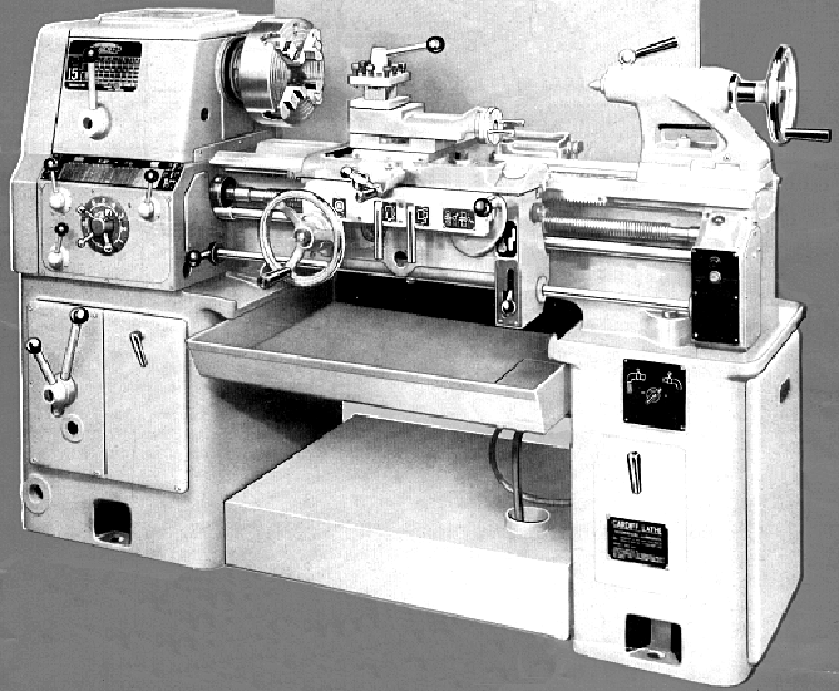
Major, a model that was also produced in a rare 8-inch and well as unpublicised 7-inch versions. All three types were available with between-centres capacities of 30", 40" and 60". The two longer versions could be ordered with a gap bed, with the 30-inch capacity, non-gap type called, by a piece of meaningless advertising hyperbole, the "Chip Flow". This had a straight section of bed in front of the chuck with the centre opened up to allow swarf to fall through more easily. The bed was enormously wide, one-and-a-half-times the centre height, a figure better than many toolroom lathes whose beds only equalled or slightly exceeded it. The drive system was interesting and reflected, again, a practice normally reserved for toolroom and better-quality lathes where, in order to prevent the transmission of vibration-induced "gear-tooth" marks to the turned surface, the main transmission gearbox was mounted in the cabinet base next to its (3 h.p.) electric motor. The 9-speed gearbox was a very heavy-duty affair, oil-pump lubricated and containing forged-alloy, hardened and ground gears; the speeds were changed by two concentrically-mounted levers on the front face of the heavily-built stand.
Made from a ground-finished, heat-treated alloy-steel forging, the headstock spindle ran in a pair of precision grade, opposed taper-roller bearing on its nose and, at the rear, in a parallel roller race. The nose fitting was a No. 5 Morse taper and the bore 1
17/32" (39 mm).
Drive to the headstock was by twin V-belts on the 7-inch model and triple on the others, the belts wrapping around the headstock spindle between its bearings. On the 7-inch, the inside of the headstock was "open", the backgears and bearings being lubricated by grease and oiling nipples provide for the other shafts. On the other models, the headstock was more robust and divided into two compartments, the front containing the slow-speed back gearing lubricated by splash with oil fed to the front spindle bearings; those on which the V-rope pulley ran in the rear section (which was otherwise dry). The rear bearing was grease lubricated, the makers suggesting the application, weekly, of a grease gun to the nipple provided beneath the changewheel door.
Tension of the V-belts could be altered by changing the position of the (patented-design) eccentrically-mounted output pulley on its gearbox shaft. Combined with the conventional backgear assembly (as previously described, situated immediately behind the front bearing) a  total of eighteen spindle speeds from 27 to 757 R.P.M were available, or, fitted with the optional high-speed pulley set, 35 to 1000 RPM. At first - on what appears to have been the just the 7-inch and 7.5-inch models - the spindle-end fitting was of a most unusual quick-release type with the spindle ending in a flange but with a narrow, knurled-edged "thrust plate" fitted immediacy behind it. The flange and plate were each drilled with four holes into which fitted threaded studs on chucks and faceplates; to remove a spindle fitting, the nuts were slackened and the thrust plate rotated slightly to line up the holes - whereupon the fitting could be slid off. A photograph below shows how the system worked. However, although found on may examples of these lathes, a more common fitting was an American long-key taper in a size L0 .
Double-walled, the apron had its gears lubricated from splash from a sump, with the selection of feeds by well-thought-out, patented snap-action controls; the electrical stop, start, forward and reverse of the headstock spindle could be controlled by two levers, one mounted immediately in front of the headstock the other on the right-hand side of the apron.
An oil pump forced oil around the screwcutting gearbox, a box that was able to generate either 45 English or 20 metric threads at the flick of a lever whilst additional gears of 30T, 66T and 21T were supplied as standard to extend the threading range to pitches below the 23/4 to 80 t.p.i (and 0.1875 mm to 5 mm) range offered as standard. A variety of Diametral and metric module pitches was also available and listed, together with their required changewheels, on a comprehensive chart above the gearbox. The shear-pin protected leadscrew was mounted in tension and could, claimed the makers, be reversed end for end to prolong its life. Unlike its Colchester equivalents, the Cardiff was mounted, not on a heavy, sheet-metal stand, but on large cast-iron boxes between which was a useful slide-out chip tray. If you have to install a heavy lathe in an awkward place, or several floors up in a building, the fact that a Cardiff can be broken down into smaller parts relatively easily makes it an ideal candidate for the job.
The set-over tailstock was held down by one central clamp, fastened by a single nut for which the maker's provided the usual self-hiding spanner. The barrel had a travel of 4.75" and carried a No. 3 Morse taper.
A strong, no-nonsense and easily-operated lathe, the Cardiff Major was capable of sustained hard work and popular with both self-employed engineers and larger jobbing shops.

Elliott Cardiff "Major" 7" and 7.5" and 8" x 30" lathe circa 1958

Elliott Cardiff 8.5-inch centre height "Senior" model.
The Prefect and Crusader looked identical

Continued:
Of almost identical appearance, the larger
Senior, Prefect and Crusader models were all, apart from the castings associated with their different centre heights and their headstock spindles, built largely from the same parts. They all used an almost exactly similar design of cabinet-base-mounted 9-speed gearbox and backgeared headstock drive system as the Major and the carriage was also built along very similar lines - including the built-in spindle controls on the apron. The headstocks however were much more massively built and the oil-pump fed screwcutting gearboxes arranged along completely different lines. All were available with a choice of three sturdy, cross-ribbed gap beds that allowed 30", 48" or 80" to be admitted between centres - with the two larger models having the option of a gap bed and the shorter the so-called "chip-flow" design.
The 8.5" centre height (17-inch swing) Senior Model had 18 speeds that could be ordered from the works with ranges of 12 to 500 rpm, 20 to 970 rpm or 25 to 1200 rpm. The 1.75" (45 mm) bore hardened and ground spindle ran in twin opposed precision taper roller bearings at the front and a parallel roller race at the rear; the hardened headstock gears ran in an oil bath from a pumped supply.
Both the 9-inch centre height "Prefect" and 11-inch centre height "Crusader" were massive machines that weighed from 6188 lbs for the short-bed Prefect to 8184 lbs for the 80-inch capacity Crusader - with all models having usefully-large 3.0625" bore headstock spindles.  The 18 spindle speeds ranged from 20 to 1000 rpm on the Prefect and 15 to 750 rpm on the Crusader, both were fitted with 10 h.p. motors of 1460 rpm on 50 cycles or 1750 rpm on 60 cycles.
With a generous range of feeds and threads on both models, the screwcutting gearbox provided a : 80 sliding feeds from 0.0023" to 0.232" per revolution of the spindle and 80 surfacing feeds from 0.0009" to 0.096";  56 English threads from 1/2 to 30 t.p.i, 24 metric from 0.5 to 30 mm pitch, 27 diametral pitches (using alternative changewheels) from 2 to 30 D.P. and 13 metric modules (again with a different changewheel set) from 15 to 1/2.
On all larger models the tailstocks were given two bed clamping bolts and had a No. 4-Morse tapers in the barrel..

Wide and deep. The two longer versions of both the Major and the three larger Cardiff lathes could be ordered with a gap bed whilst the 30-inch capacity versions of all models had what the makers called a "Chip Flow" design - with that section of the bed normally occupied by the detachable gap bridge replaced by a straight piece with the centre section opened up to allow swarf to fall through more easily. The bed was enormously wide, one-and-a-half-times the centre height, a figure better than many toolroom lathes whose bed widths only equalled or slightly exceeded it.

The drive system was interesting and reflected a practice normally reserved for toolroom and better-quality lathes where, in order to prevent the transmission of vibration-induced "gear-tooth" marks to the turned surface, the main transmission gearbox was mounted in the cabinet base next to its (3 hp) electric motor. The 9-speed gearbox was a very heavy-duty affair, oil-pump lubricated and containing forged-alloy, hardened and ground gears; the speeds were changed by two concentrically-mounted levers on the front face of the stand.

Drive to the headstock on the 7.5 and 8-inch models was by triple V belts that wrapped around the headstock pulley between its bearings and whose tension could be set by altering the setting of a (patented) eccentrically-mounted output pulley on the gearbox. The headstock itself contained a conventional backgear assembly, clustered immediately behind the front bearing, so producing a total of eighteen spindle speeds from 27 to 757 rpm or, fitted with the optional high-speed pulley set, 35 to 1000 RPM. An America L0 taper or, alternatively, the maker's thrust-plate arrangement, was fitted to the hardened and ground, 5 Morse taper spindle which was bored 117/32" (39 mm) and ran on twin opposed precision taper rollers at the front and a parallel roller race at the rear.

At first - on what appears to have been the just the 7-inch and 7.5-inch models - the spindle-end fitting was of a most unusual quick-release type with the spindle ending in a flange but with a narrow, knurled-edged "thrust plate" fitted immediacy behind it. The flange and plate were each drilled with four holes into which fitted threaded studs on chucks and faceplates; to remove a spindle fitting, the nuts were slackened and the thrust plate rotated slightly to line up the holes - whereupon the fitting could be slid off.

The pressure-lubricated screwcutting and feeds gearbox could generate either 45 English or 20 metric threads at the flick of a lever with additional gears of 30T, 66T and 21T supplied as part of the regular equipment to extend the threading range to pitches below the 23/4 to 80 t.p.i and 0.1875 to 5 mm range offered as standard. Ranges of Diametral and metric module pitches were also available and listed on the comprehensive chart above the gearbox.

Changewheel bracket with nuts on the front of the gear studs allowing quick changes of ratio when special threads had to be cut.

Hardened and ground, the gears in the oil-immersed apron were controlled by well-thought out, patented snap-action controls with levers, mounted on a shaft travelling the length of the bed, provided by both the headstock and on the apron, to control the electrical stop, start, forward and reverse of the headstock spindle. A dial thread indicator was built in to the right hand side of the saddle and the extra-large top-slide micrometer dial would have been appreciated by a busy operator.

Interior of the "Major" apron. The handwheel for carriage traverse was fitted with a micrometer dial.

The taper-turning unit was especially well thought out with the unit brought into operation by tightening just the two bolts holding the anchor bracket to the bed and once in use it was still possible to operate the cross slide normally. The scale was marked both in degrees and inches of taper per foot.

                    A poorly designed fixed steady with very limited capacity.                             Travelling steady

A 4-way toolpost was standard, but the slide to which it was fitted was not T-slotted making changes difficult than they should have been; however, an alternative toolpost, below, included a T-slotted casting.

                         Boring table to replace cross slide                              American-type toolholder that came complete with a T-slotted top

Omnispeed, Omnitool & Omniturn Lathes

Elliott Milling Machines

Handbooks and Parts Lists
are available for most Elliott machine tools

Elliot Cardiff Major, Senior, Prefect, Crusader,
Omnispeed, Omnitool & Omniturn Lathes

email: tony@lathes.co.uk
Home   Machine Tool Archive   Machine-tools Sale & Wanted
Machine Tool Manuals   Catalogues   Belts   Books  Accessories