email: tony@lathes.co.uk
Home   Machine Tool Archive   Machine-tools Sale & Wanted
Machine Tool Manuals   Catalogues   Belts   Books   Accessories

"Zenith" Milling Machine

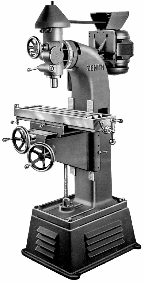
Advertised from the late 1930s until at least the late 1940s the "Zenith" vertical miller was by marketed by the G.Elliott Machine Tool Group and, if not a disguised import, might have been built in one of their many factories, probably that of the Victoria Machine Tool Co. Ltd. in Willesden, North London. Victoria were well known for their extensive range of well-made medium to heavy-duty horizontal, vertical and universal models usually badged as "Victoria" and a less-expensive range sold branded as the "Pallas" brand. However Elliott were well known (along with many other such dealers and distributors) in "re-branding" a wide range of machine tools for the UK market and it might be that the "Zenith" was actually made by, for example, Columbia Enterprises, Inc., of Grays Lake, Illinois, who made a range of rather similar machine during the same period.
Of simple and straightforward design and construction (and obviously intended to undercut even the Pallas Models), the Zenith was, at 1030 lbs, of relatively light construction with a main column so narrow that in order to achieve a reasonable degree of separation the knee ways were forced to overlap the outside edges of the column's front face. Despite the resulting skimpy appearance the machine has a very reasonable range of movements with the hand-feed 32" x 8" table travelling 18-inches  longitudinally, a generous 9-inches in traverse and 15-inches vertically. The maximum clearance between spindle nose and table was 15
1/2" and the distance between the spindle centre line and the inside face of the column 9-inches.
The table carried three 5/8" T slots spaced 1
5/8" apart was provided with a wide suds drain around its periphery (which somewhat reduced the clamping area).  Although bolted-in "gib blocks" (rather than loose "gib strips") were used to adjust the fit of table to knee, and knee to column, only a single locking screw was fitted to each axis, this unfortunate cost-cutting exercise would have provided every opportunity for an "interrupted cut" to vibrate the locked slide from its secured position.
Carried on the end of a round shaft that passed horizontally through the top of the column, the vertical head was driven by a motor secured to a plate at the other end. Developing 1 h.p. at 1400 r.p.m. the motor drove forwards by a V belt running over 5-step pulleys to give a speed range of: 525, 900, 1400, 2170 and 3730 rpm. Alternative speed ranges were also available: a 700 r.p.m. motor giving 260, 450, 700, 1085 and 1865 r.p.m. and a 900 r.p.m. motor 340, 580, 900, 1390 and 2400 r.p.m. It is not clear how (if at all) the belt tension could be relaxed to allow changes of speed. The head was clamped in place by three 5/8" bolts which, when slackened, allowed the head to swivel 120º in either direction. The spindle was hardened and ground, ran in two double-row radial thrust ball-bearings and was moved through its 4-inches of travel by a handwheel turning a robust worm-and-wheel mechanism. Locked by good-sized compression clamp, the spindle was bored through 1/2" to allow a draw bar to pull collets or other fittings into the No. 10 Browne & Sharpe taper - and unusual choice for an English machine and a possible confirmation of its American origins.
Supplied with each new machine was just an electric light and motor pulley, everything else being extra. Accessories included a table power-feed attachment, a choice of different motors and speed ranges (though no speed-reducing "backgear" assembly) and the usual range of rotary tables, dividing heads, swivelling machine vices, boring heads and angle plates..

Zenith Vertical Milling Machine circa 1939

The head was clamped in place by three 5/8" bolts which, when slackened, allowed the head to swivel 120º in either direction.

The spindle was hardened and ground, ran in two double-row radial thrust ball-bearings and was moved through its 4-inches of travel by a handwheel turning a robust worm-and-wheel mechanism. Locked by good-sized compression clamp the spindle was bored through 1/2" to allow a draw bar to pull collets or other fittings into the No. 10 Browne & Sharpe taper - an unusual choice for an English machine, even then.

The table carried 3 T-slots spaced 15/8" apart and was provided with a wide suds drain around its periphery (which somewhat reduced the working area).  Although bolted-in "gib blocks" (rather than loose "gib strips") were used to adjust the fit of table to knee, and knee to column, only a single locking screw was fitted to each axis and this unfortunate cost-cutting exercise might well have caused an interrupted cut to induce vibration in the locked slide.

email: tony@lathes.co.uk
Home   Machine Tool Archive   Machine-tools Sale & Wanted
Machine Tool Manuals   Catalogues   Belts   Books   Accessories

"Zenith" Milling Machine