|
Continued:
A reader writes:
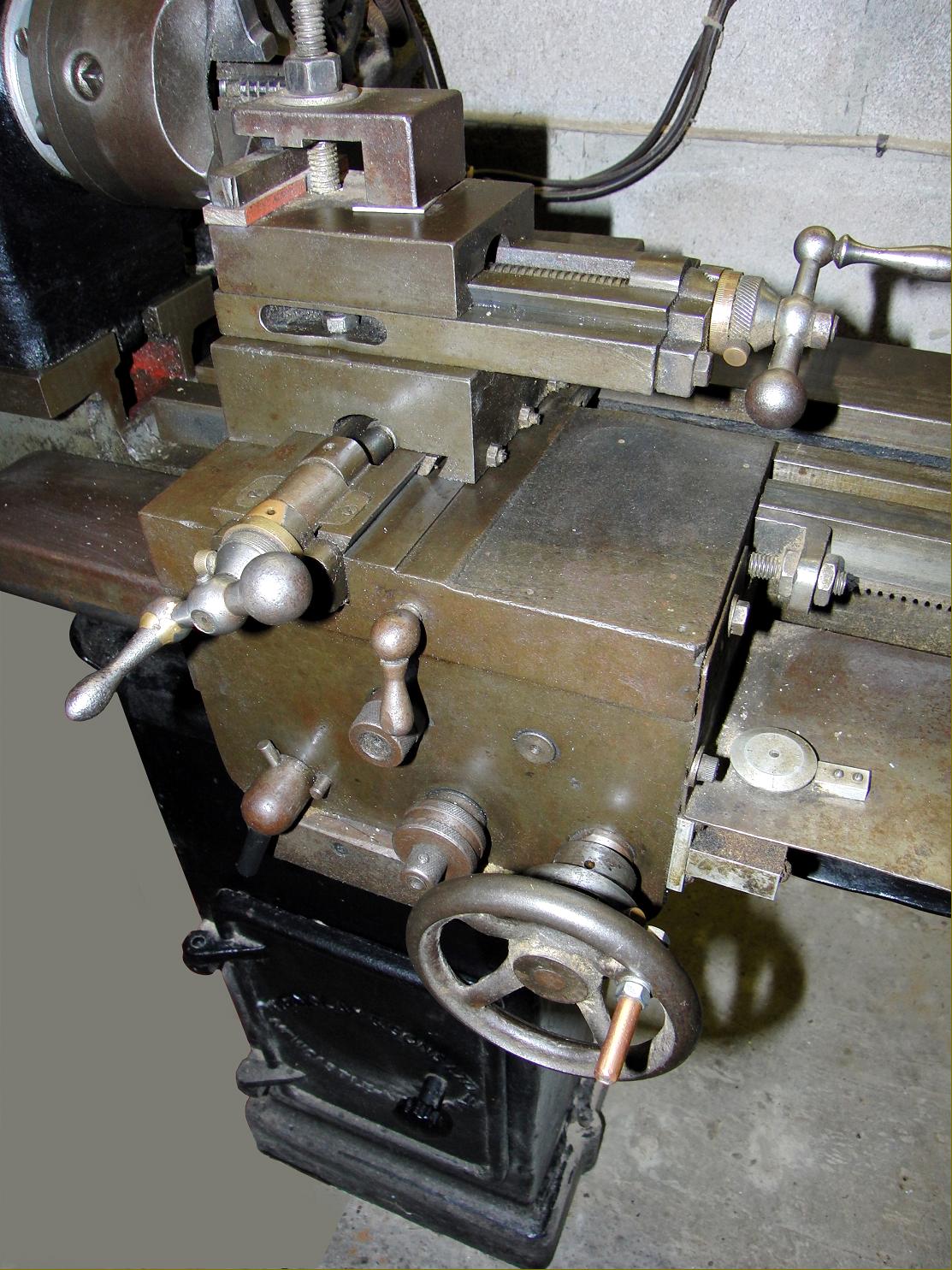
My Wilfin lathe, which I would date as 1940s/1950s, has certain resemblances to the 71/2" Fielding lathe featured in the 'Fielding' section of your website - notably the shape of the headstock, the arrangement of the short cross-slide (allowing swarf to get on the slides and feedscrew), the circular 'cut-out' in the topslide base for the fixing bolts (a real swine to get the spanner on), the diagonal webs in the bed casting and, in particular, the unusual slot in the top face of the front shear - this, in conjunction with a taper gib on the front of the shear, forming the carriage guide. For some strange reason, the front face of the shear is around 2 degrees off a true right-angle to the top face. At first I thought this was excessive wear, but it extends the whole length of the bed, so must have been intentional (or caused by poor machining when the bed was planed!). Possibly the designer had access to a Fielding at the time, or (and I have no evidence for this) Fielding actually made the Wilfin for Wm Findlay.
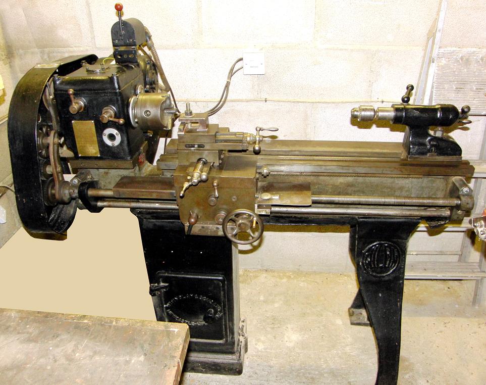
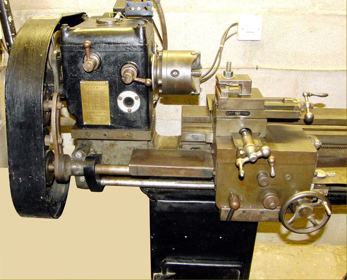
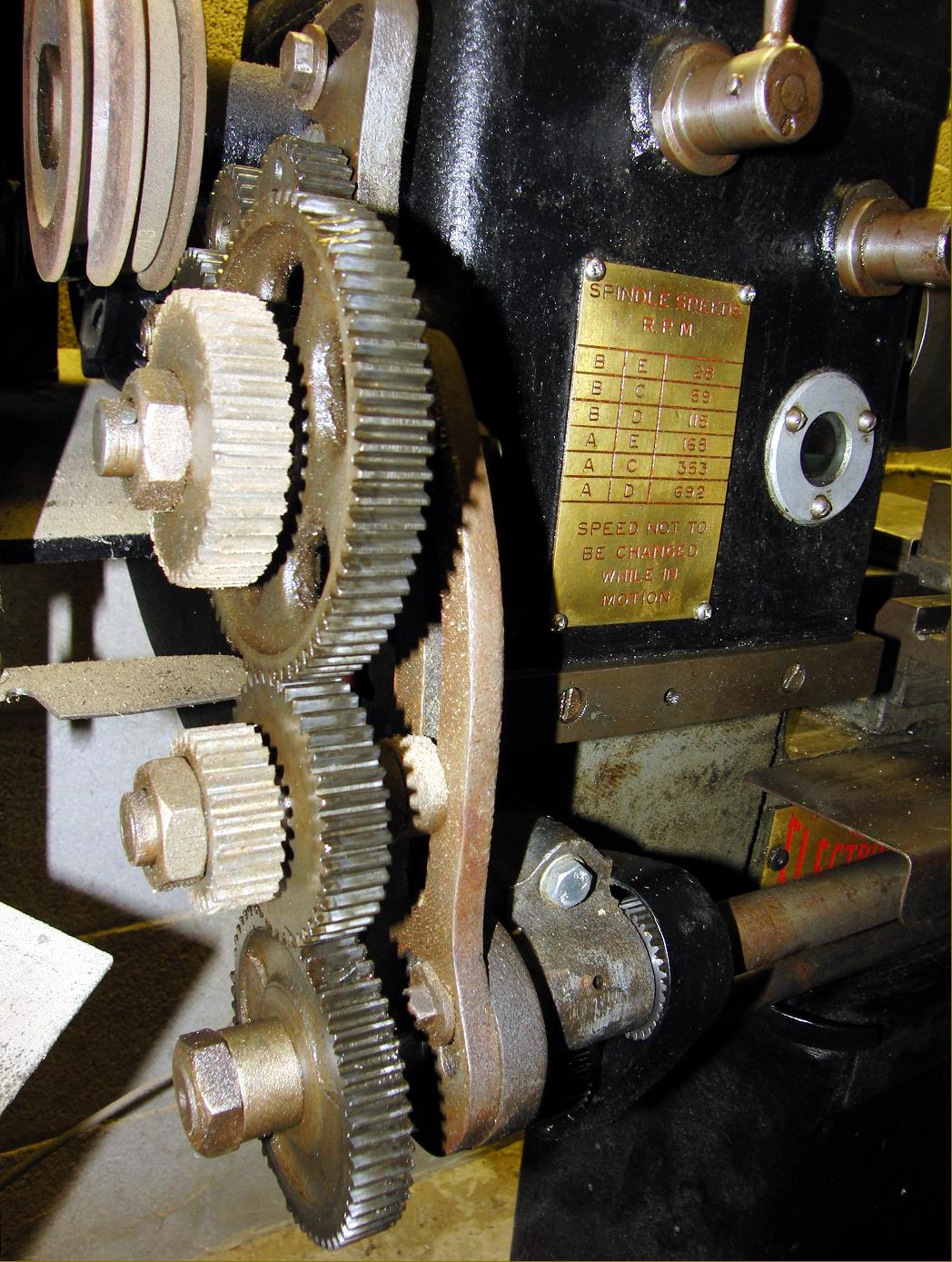
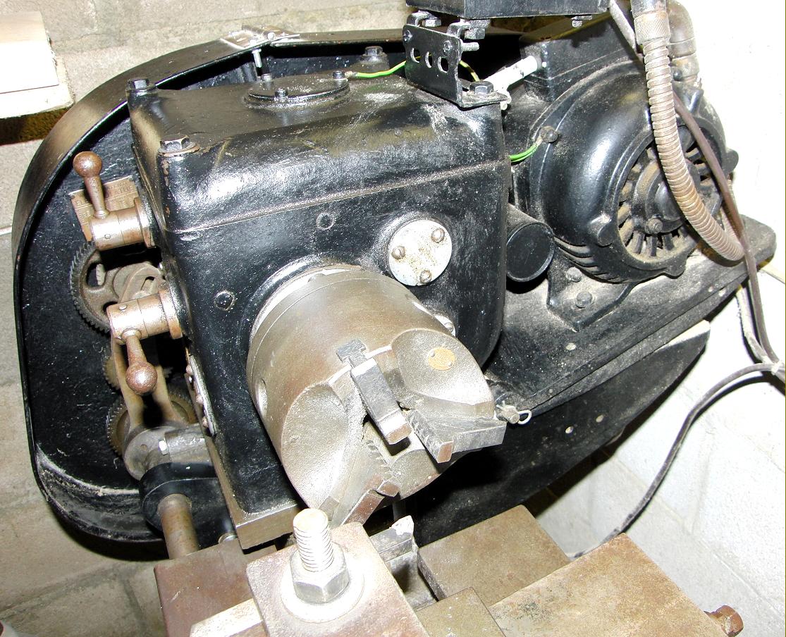
My lathe has a 6-inch centre height, accepts around 28" between centres and the tailstock end standard carries a brass plate crudely stamped 'MC Ref PCN 23474 A' and 'Makers Serial No. 713' which, as this is probably a fairly late machine, tends to support my view that not many 'Electrolathes', of any description, were made. It will swing approx 16" in the gap and has a 6 speed geared head (28, 59, 115, 168, 353 and 692 rpm), driven from a twin V-belt primary drive, with no clutch. It is on its maker's cast iron cabinet (headstock end) and an A-frame (tailstock end) plinth, with a pressed steel chip tray. When purchased it had an enormous cast-iron motor mounting on the back of the cabinet stand, big enough to take a 2 h.p. motor, though the 3/4hp single phase motor now fitted seems amply powerful. The leadscrew is driven via a conventional set of changewheels, the set acquired with the lathe being comprehensive and including a 127t transposing wheel for metric threads. It had a form of tumbler reverse for the screw cutting train, but, with only 2 gears, this meant that the gear train quadrant had to be adjusted each time 'forward,' 'neutral' or 'reverse' were selected. The quadrant arrangement appears identical to that on the belt drive lathe shown on the website.
The half nut arrangement for screw cutting is just that - a top half of the split nut only, with an adjustable support on the apron below the leadscrew (just like a Myford/Drummond M-Tyope, to prevent deflection of the leadscrew when the half nut is engaged. There is a separate drive shaft, permanently meshed to the leadscrew, for longitudinal and transverse feeds. These feeds are engaged by pulling or pushing a knob on the front of the apron, and, typically, are very hard to disengage under load as the mechanism "winds up" - though an adjustable cone clutch gives some measure of overload protection for the feed-drive mechanism if the operator fails to the drive. There is a machined facing on the front of the bed, below the headstock, (painted over in the photographs), which, presumably was for an optional screwcutting gearbox. The topslide and cross-slide feedscrews are both fitted with small diameter dials, typical of the period, graduated in thousandths of an inch. Both feedscrews are 'wrong handed', inward feed being made with an anti-clockwise turn. The tailstock barrel, and main carriage handwheel feed in the conventional direction, however, and the bed-locking clamp is of the 'loose-spanner' variety. End play adjustment of the leadscrew and feedscrews is made with nuts on fine-pitch screws, which were initially a puzzle, as they were of strange diameters. Eventually, I realised that they were standard electrical conduit threads!
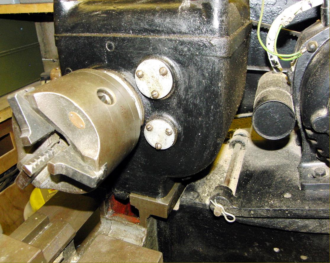
The worst feature of the lathe is the headstock spindle, which, while having a substantial 1½" threaded nose, is only bored 5/8", with 2 Morse taper socket. (The tailstock barrel is bored 3M/T). The spindle bore restriction is because the shaft diameter within the headstock is only 1" -definitely on the light size for a machine of this size. When purchased, the main gear cluster, which runs on the spindle in the headstock, was seized on the shaft, which is hardly surprising as it's a steel gear running on a steel shaft, with only splash lubrication. While the main spindle runs in taper roller bearings, the gearbox input shaft makes do with bronze bushes. There is no form of oil seal on any of the headstock bearings, so oil loss, particularly at higher speeds, can cause quite a mess. I use 20/50W motor oil in the headstock, not ideal, I know, but it's cheap, and being fairly thick tends to stay in better than the 10W I probably should use.
When I bought it, it was painted cream, but the original paint seems to have been a darkish blue, possibly hammer finish.
So, I have probably made the Electrolathe sound like a pile of junk that no-one in their right mind would own, but I've had mine for 15 years now, until recently as my only lathe, (I now have a small 'Chinese' lathe which runs up to 2500 rpm for the small stuff) and have done a lot of work with it, including making a Dore Westbury milling machine, and a Tasker 4" scale steam tractor, and I still have no thoughts of getting rid of it. It has about the same 'footprint' and weight as a Boxford, but an extra 1" in centre height - which is really useful. I have done a fair amount to it, and overcome a lot of the problems, as follows:-
· New topslide and cross slide nuts and feed screws that twiddle in the right direction.
· Bored out the main headstock cluster gear, and fitted a turned down 'oilite' bush, to stop the gear seizing on the spindle. (OK, I know you are not supposed to machine sintered bronze bushes, or fix them with 'Loctite', but I did both, and it has run for 15 years without any problems.)
· Made a tumbler reverse assembly that actually reverses, and doesn't need a spanner to do it.
· Lever/cam operated tailstock locking device.
· Graduated divisions on the tailstock barrel.
During the 1930s a Wilfin wood-turning lathe was also manufactured and patented, apparently, under No. GB414496 of 1934. However, this turns out to be just one of 5 patents granted to Robert Peden Findlay and concerns not a wood lathe but details of a very simple countershaft arrangement i.e : Motor driving arrangements. FINDLAY & SONS, Ltd., W., and FINDLAY, R. P., 69, Side, Newcastle-on-Tyne. June 13, 1933, No. 16689. [Class 35.] In a drive for a lathe, drilling-machine, or similar rotary machine tool, or for mill gearing, a motor a driving the lathe or other spindle f by a belt P running over cone pulleys R, S is mounted on a plate B hinged at C to a bracket E adjacent the headstock &c. The plate B may rest on stops G which are adjustable to vary the belt tension. A clamping bolt m may be provided for holding the plate against the stops and is formed with a cam projection H so that when the nut N is slacked off, the bolt may be swung about a pivot to raise the plate and slacken the belt.
If any reader has a Wilfin lathe, or any knowledge of the makers, the writer would be interested to hear from you.
|
|