|
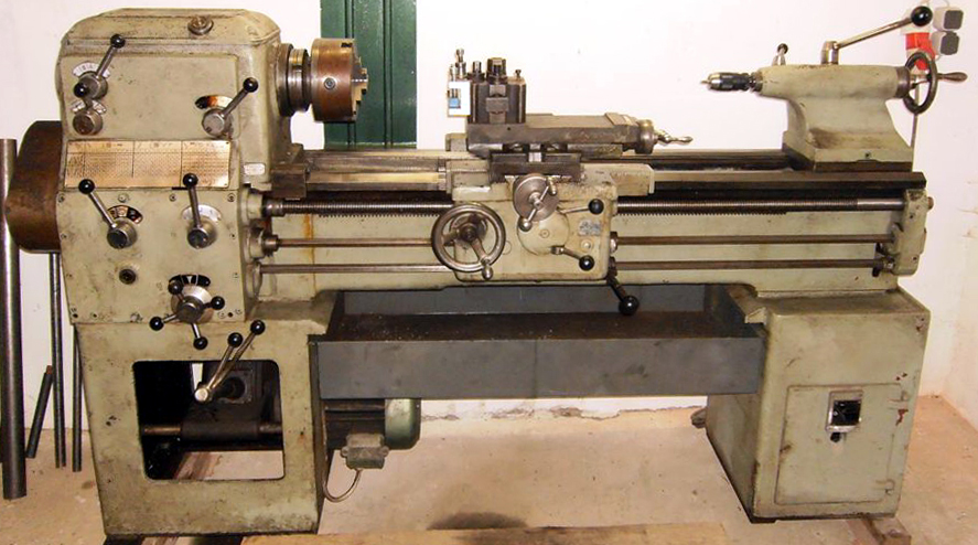
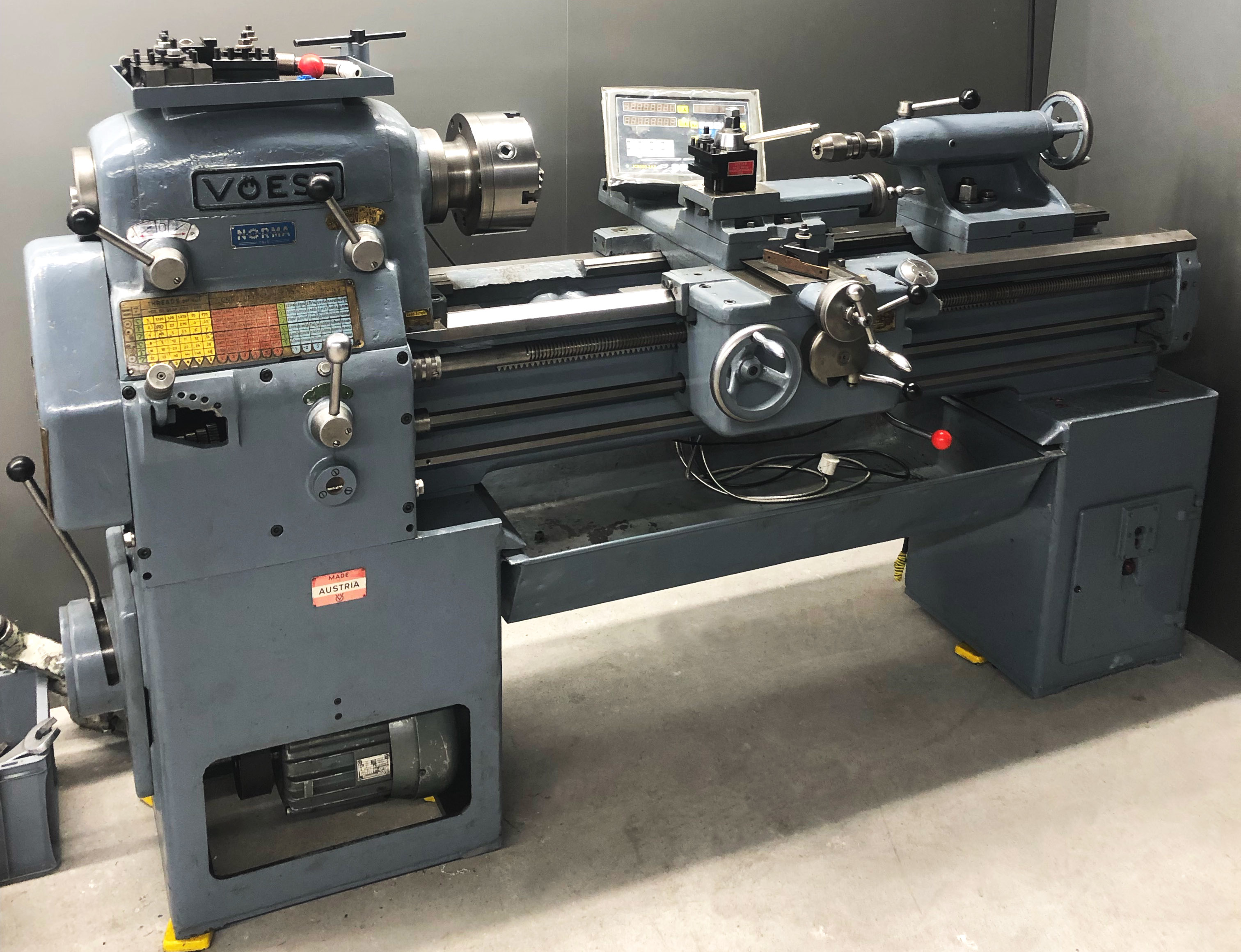
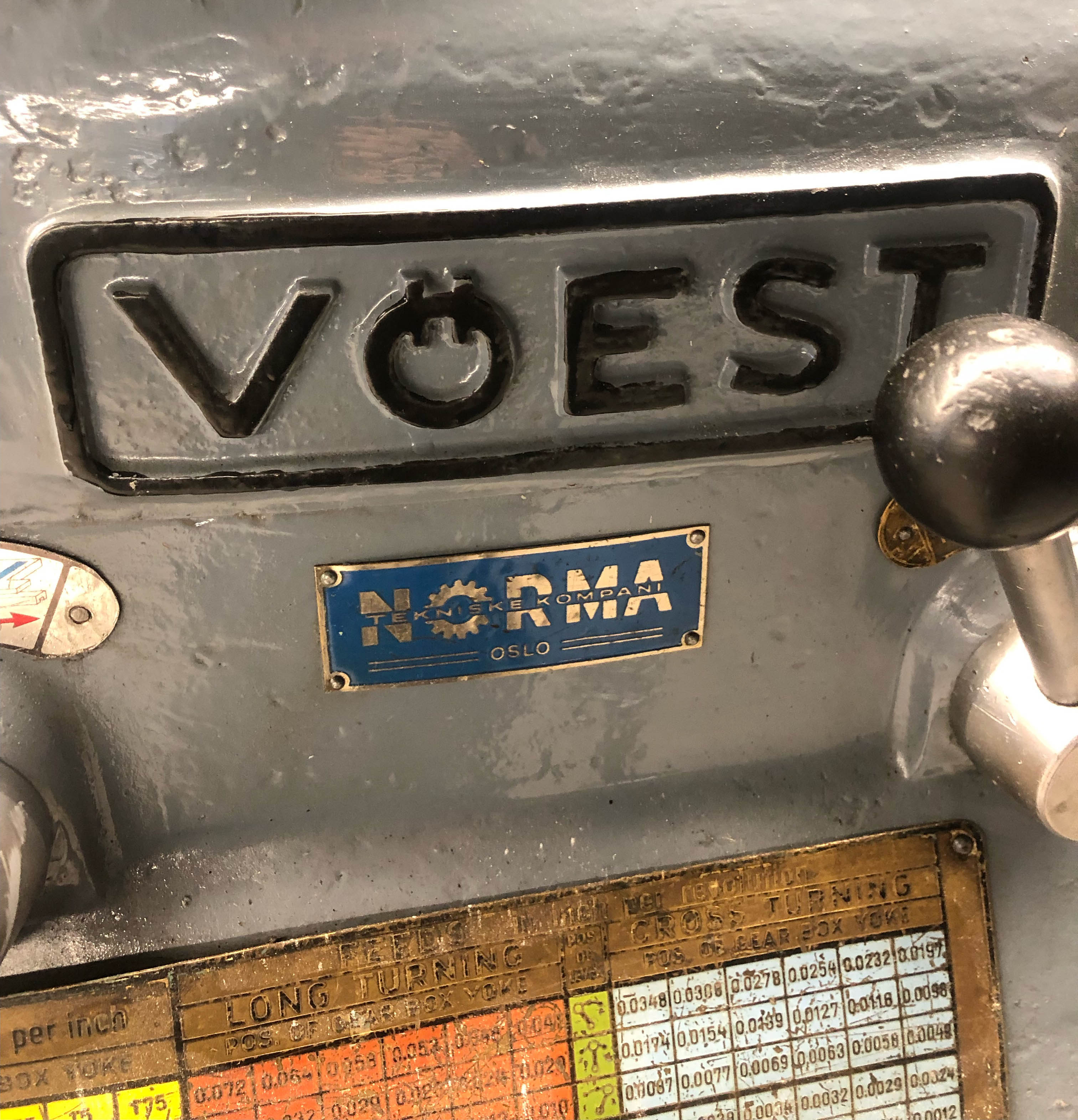
Manufactured in Linz-Donau, Austria by the Vöest Company (now part of the vast Vöest-Alpine Group) the DA Series of lathes were, apart from a re-badged Emco V13 sold as the DA160 (the original probably based on a French Vernier design), heavily-built machines made in 180 mm (7"), 210 mm (8.125") and 225 mm (8.6") centre heights. They were constructed to Din 8606 standards and designed to compete with established models, such as the Colchester Mascot, at the heavier end of the general-purpose workshop lathe market. Three between-centres capacities were available of 1000, 1500 and 2000 mm with the shortest bed model offered with the option of a detachable gap able to accommodate a piece of material 440 mm (17.25") in diameter and 235 mm (9.25") thick. The two longer-bed machines had gaps with the capacity enlarged to 570 mm ( 22.5") on diameter, but with no additional increase in the length that could be swung. The 13-inch wide bed was very deep, with massive diagonal ribbing, and the 1000 and 1500 mm between centres models could be supplied, at extra cost, with induction hardened ways to a minimum specification of 300 Brinell. Early and late versions of the model were made, those from the 1950s and 1960s being of typical rounded appearance and the later types with much more modern, angular styling. However, mechanically, the lathes were little changed - with all the control systems remaining exactly as before.
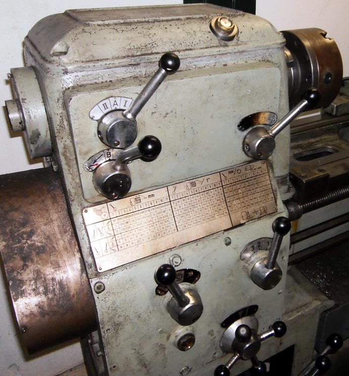
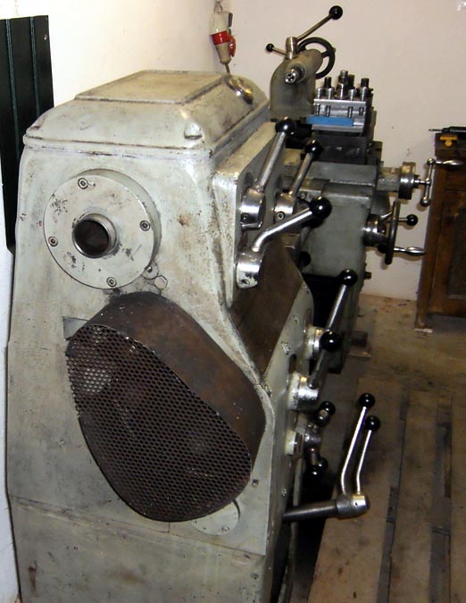
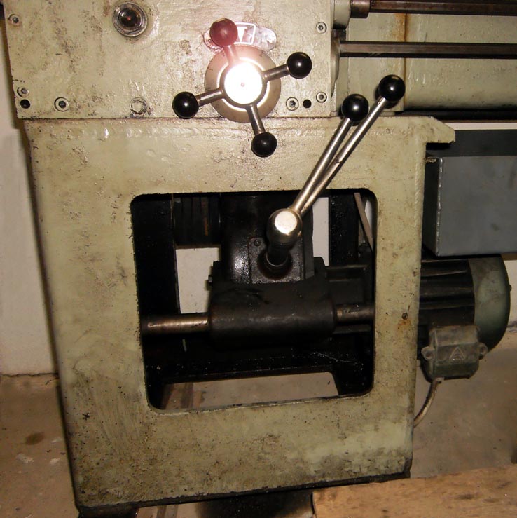
By using a system normally only found on better classes of toolroom lathe, with a speed-change gearbox in the cabinet stand and the drive to the headstock spindle by belts, the makers had taken unusual care, for a general-purpose lathe, to minimise headstock vibrations and gear-tooth chatter marks on workpieces. The oil-immersed 6-speed gearbox was driven by a flange-mounted 4 h.p. motor with control by two concentrically-mounted levers on the front face of the left-hand cabinet leg. The drive to the 46 mm (1.8") bore, L0 nose, taper-roller bearing headstock spindle was by five V belts whose pulley (to further isolate the spindle, and relieve it from the effects of belt pull) was independently mounted on ball races, held within two partitioning headstock walls, with the drive transmitted from pulley to shaft by a peg. The headstock incorporated an 8 : 1 backgear assembly, with hardened gears that, together with the base-mounted gearbox, gave a range of 12 speeds from 21 to 1500 rpm. A plunger pump supplied lubricant to the headstock gearing, with a separate piped supply fed directly into the spindle bearings; a flow-checking glass ensured the operator that all was well with the system - at low speeds the pump dripped its supply against the window, whilst at higher revolutions this should have changed to a spray.
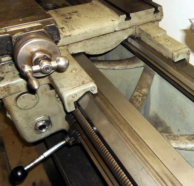
An all-lever and dial-change, oil-bath screwcutting and feeds gearbox was fitted - with no open slots to allow in swarf and dirt. The box was of the dual kind, able to generate, without changing any of the drive gears, a total of 66 English pitches (from 1 to 56 t.p.i) and 66 metric (from 0.5 to 28 mm). The 66 rates of power feed ranged from 0.07 to 4.00 mm/rev ( 0.0028 to 0.16 inch/rev) sliding and 0.036 to 2.00 mm/rev ( 0.0014 to 0.08 inch/rev) surfacing. By changing one gear it was possible to cut a range of Diametral and Module threads; the makers also gave instructions for simple rearrangements of the changewheels that produced a very fine feed rate (one-half of those normally used) and a coarse rate of twice the normal feed - though in the latter case they cautioned that only the slowest spindle speeds should be used. The shear-pin protected 4 t.p.i leadscrew was intended to be run only when screwcutting and could be disengaged from the power shaft by sliding its drive gear out of mesh. It was designed so that, when worn, it could be easily removed and reversed and the seldom-used section at the tailstock end brought into play.
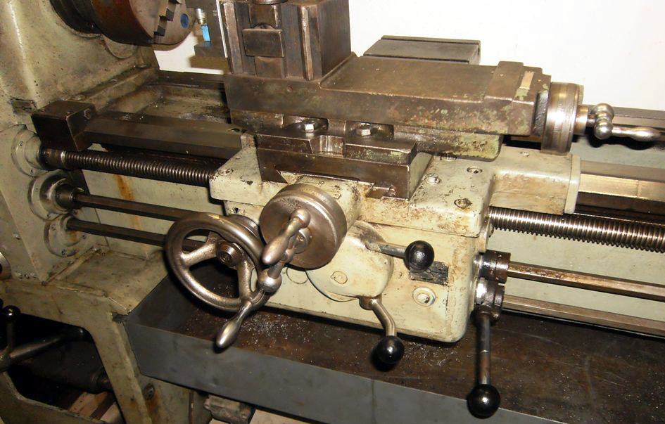
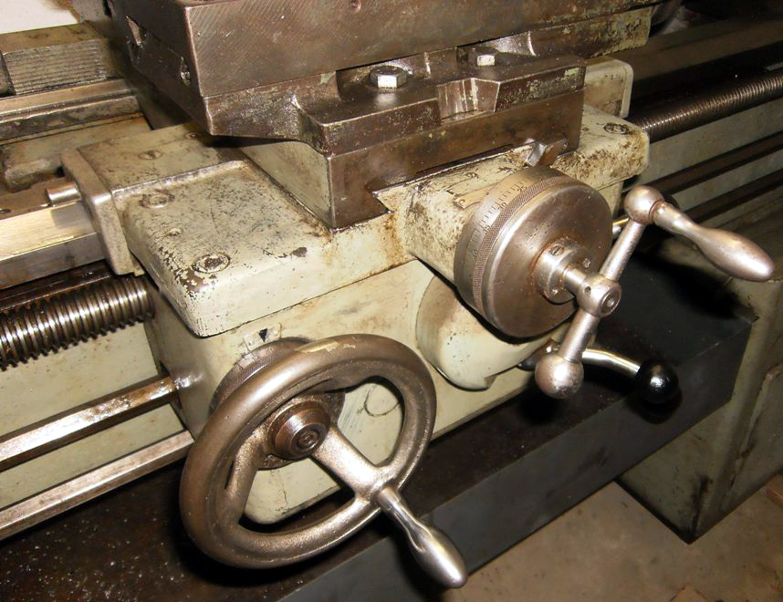
Double-walled, with a supply of oil held within its base from where it was distributed by splash to the various gears and shafts, the apron used power sliding and surfacing feeds driven by a separate shaft (protected by a shear pin). A neat, combined selector and engagement control was used with just one lever to operate and incorporating a clutch, adjustable from outside, that allowed either feed to be "inched in" carefully when approaching the end of a job. The carriage traverse handwheel was fitted with a micrometer collar, but could not be disengaged from the rack. The right-hand face of the apron carried a lever control, working through a "third shaft", parallel to and below the power shaft, that controlled the spindle electrical start, reverse and stop functions.
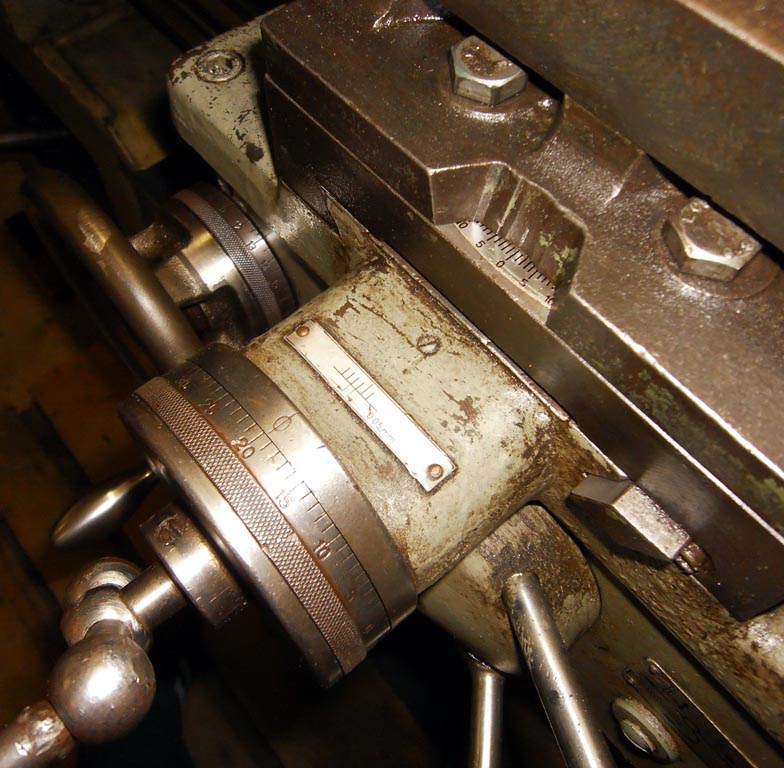
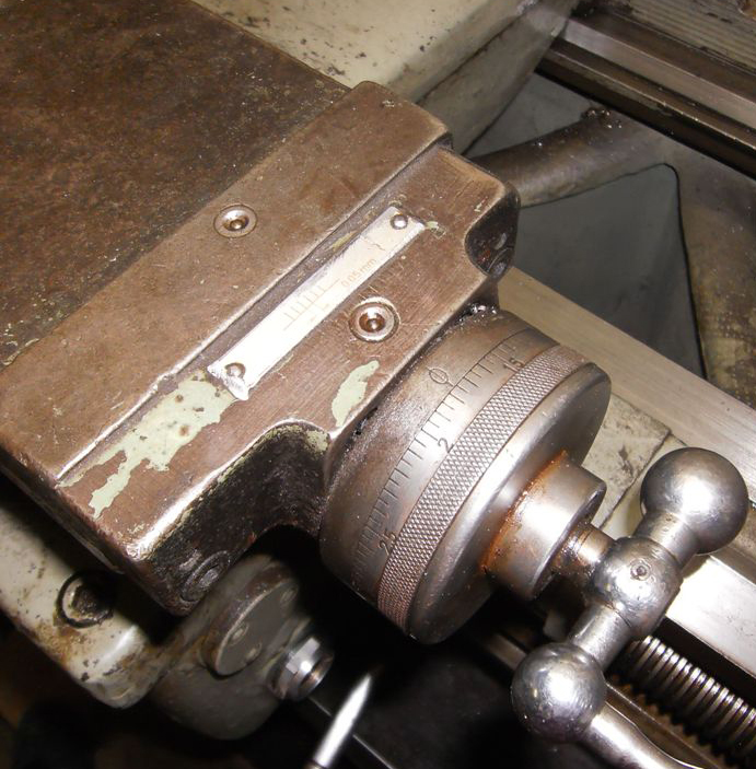
Fitted with a standard-fit 4-way toolpost, the top slide was clamped down by four bolts to a full-length cross slide that, unusually on this size of lathe, incorporated two T slots in its rear surface for the mounting of a cut-off or other type of toolholder.
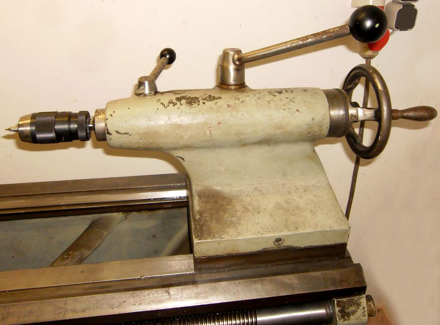
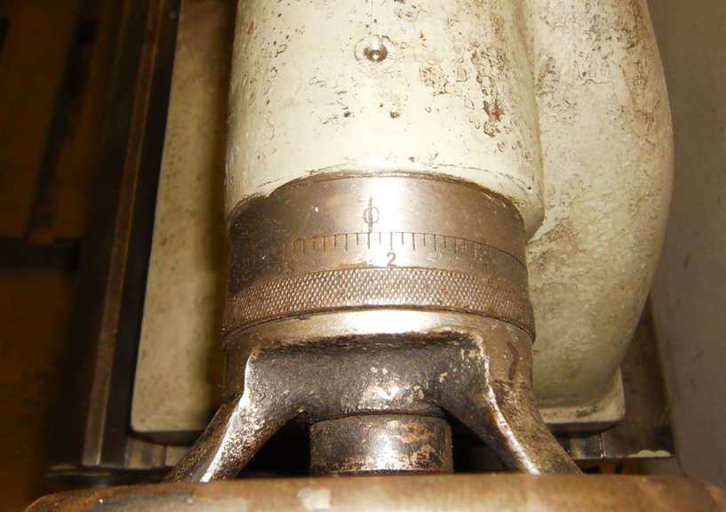
With a spindle diameter of 58 or 65 mm the tailstock used either a No. 3 or 4 Morse taper and had a top that could be off-set on the base for taper turning. As an added bonus, the handwheel was provided with a micrometer dial.
Two fabricated steel plinths were used, joined by a full-length slide-out chip tray, but unfortunately without any storage provision. Very little equipment was provided as standard, not even a 3-jaw chuck or faceplate; all that was included comprised: a driver plate, a hardened reduction Morse sleeve for the headstock spindle, 2 dead centres, oil gun, spanners and a service manual.
.A larger version of this lathe was also made which, although it looked very similar, was of 10 to 11-inch centre height and around 60 inches between centres. It has been found listed as both 20/24 x 60" and 21/28 x 60".
If you have a Vöest lathe, the writer would be interested to hear from you.
|
|