|
|
|
email: tony@lathes.co.uk
Home Machine Tool Archive Machine-tools Sale & Wanted
Machine Tool Manuals Catalogues Belts Books Accessories
Unknown Lathes - page 29
- continued here and here -
Do you recognise it ? If so, please email the author
Unknown Lathes Home page
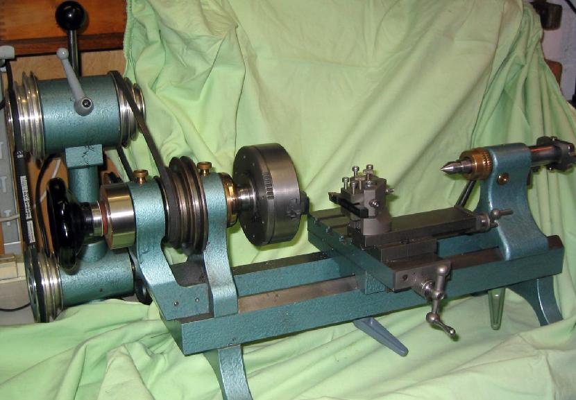
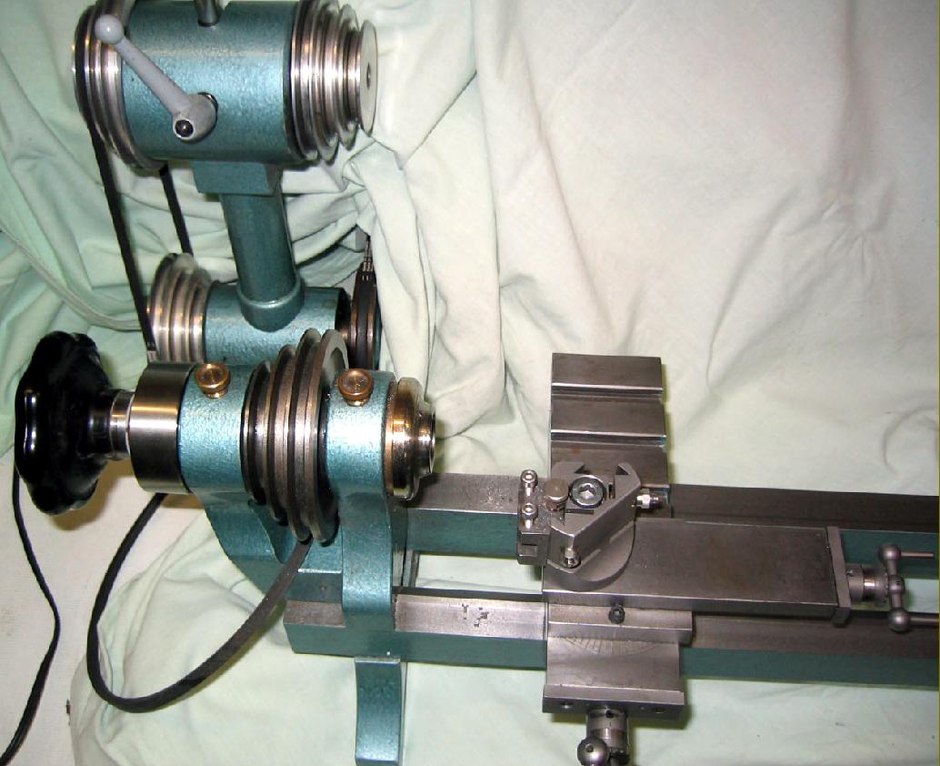
This 90 mm x 230 mm plain-turning lathe is possibly of East German origin and may well have been manufactured in the 1960s. Although evidently of the "bench precision type" for clock-making and toolroom use, some cost-cutting features and marginal engineering are clearly evident with, surprisingly, the axial adjustment and location of the headstock-shaft by clamping (or pressing and then by tightening) 2 Allen-type screws in the 3-step V-belt pulley - with not a trace of any proper axial adjustment thread and nuts. The end-float of the slide rest feed screws were also adjusted in a similar, rather peculiar manner using a single, tiny, M3 Allen-type screw. Unsurprisingly the owner reports that the collar on the top slide has as tendency to yield under pressure and is considering a modification to use two or more screws. However, both the 90 mm travel cross slide and the 60 mm travel top slide fully cover the dovetails and their feed-screws, so protecting them from the ingress of dirt and swarf - only when the cross slide is extended to its maximum extent is the sideway slightly exposed. The M3 screws to adjustment of the gib-strips do not protrude out of the slide, through it is not known if these are the same self-locking type as used by Myford for many years.
Continuing the theme of "original" engineering the tailstock has an unique way of adjustment for centering or off-setting the center. A rather short (3 cm long) hardened steel cylinder being inserted into the casting with a MT1 bore and a flange - the latter part being fixed with a bronze "swivel " nut - eccentricity being adjustable by about 1 mm in all vertical directions. Centering is done by putting a male M1 center in the headstock and a female in the tailstock then pressing or clamping and tightening of the bronze nut. One serious drawback of the tailstock was the very limited spindle travel--just 18 mm.
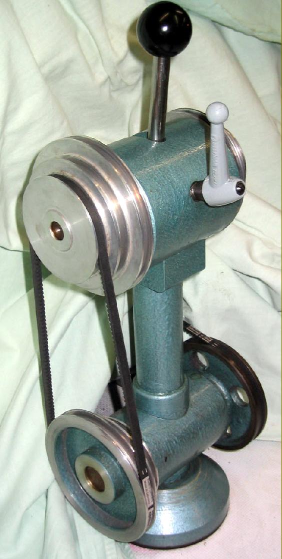
The separate countershaft is well - although its operation is difficult to visualize from the pictures. The upper part consists of a cylinder about 10 cm in diameter with an eccentric shaft and a handle to turn the cylinder through 90 degrees. If the handle points backwards the shaft is down (in clock terms; 6 o' clock) and the left as well as the right V-belts are relaxed to allow the movement of the belt from one groove to another. By pulling up the handle the shaft moves into the 9 o'clock position and both belts are tightened - a similar construction is being used by some Schaublin models.
Whilst the makers were reluctant to use more than a few Allen screws to locate vital components they still employed blocks of bronze under saddle and tailstock to accept the 8 mm clamping bolts. - continued here and here -
|
|
|
|