|
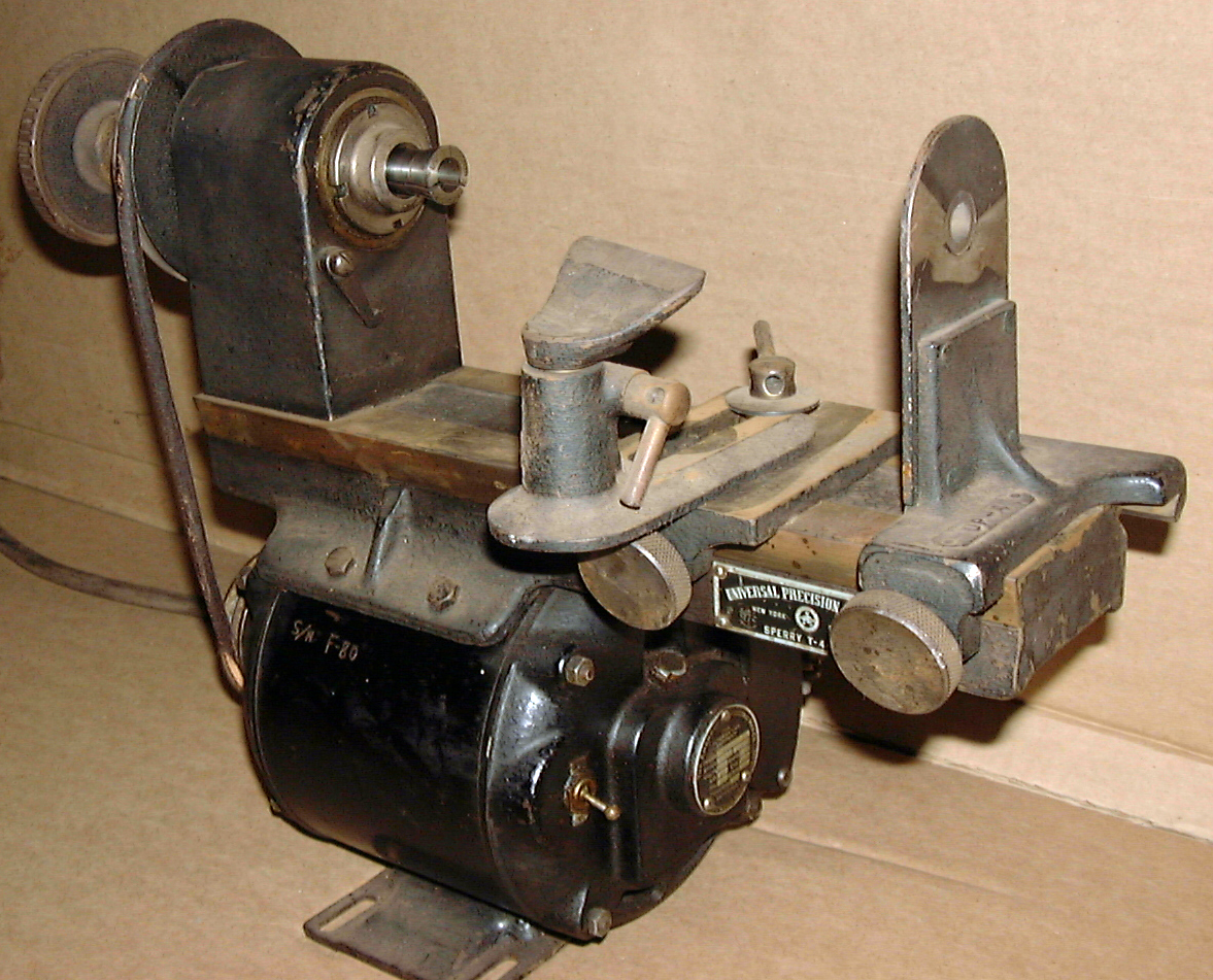
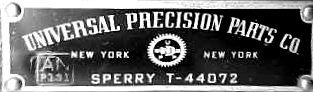
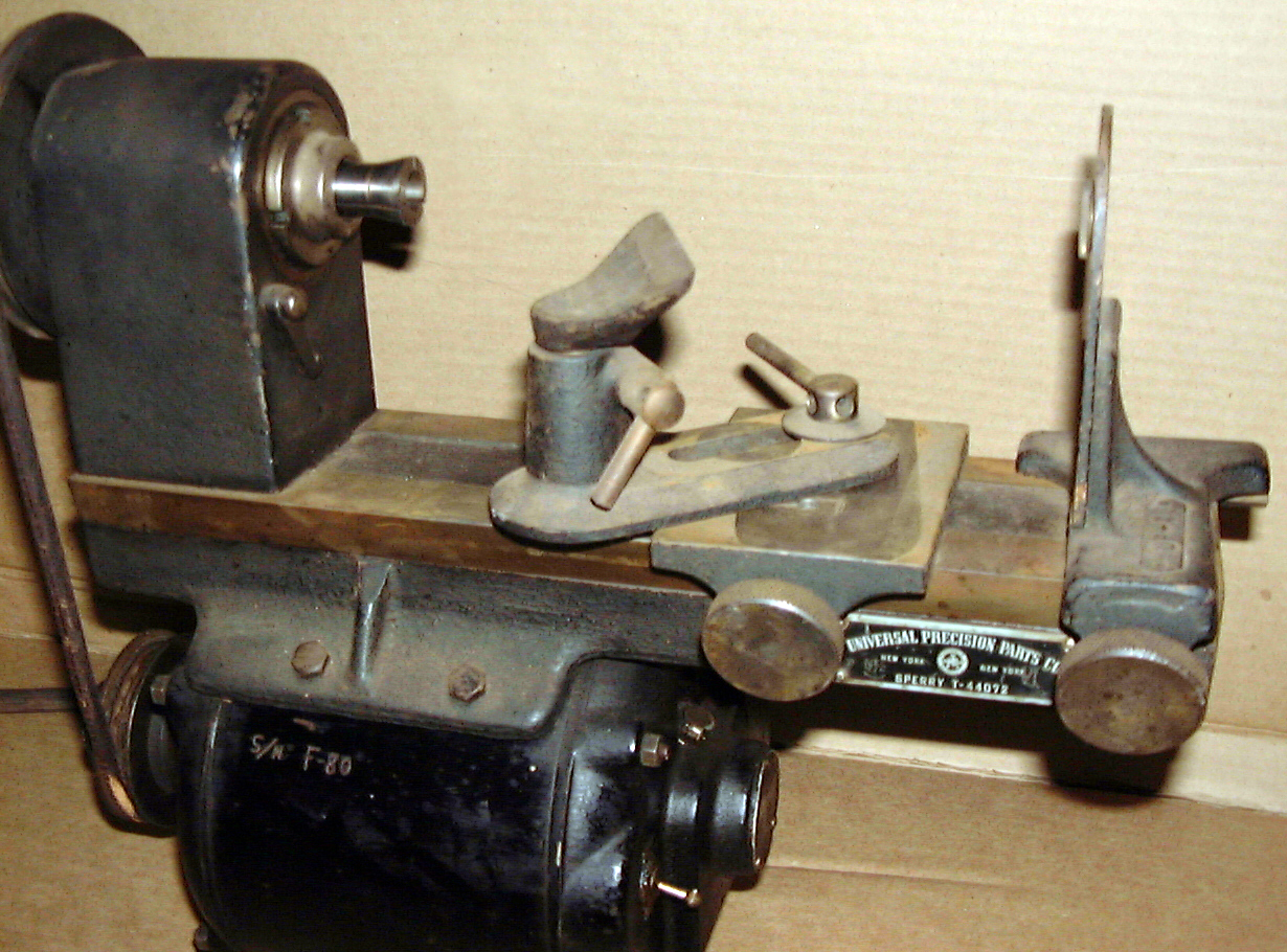
Very little is known about the background to this little 3.5-inch centre height lathe with a capacity between centres of 7.5 inches; it appears never to have been advertised for sale, but instead kept in-house for use by Sperry company's technicians. The only clue comes from labels attached to the machines, one stating "Sperry T44012" and the other Sperry T44072. Of very high-quality construction, while some have been found painted grey others have had a 'crackle-black' finished - the latter often used from the 1930s until the late 1950s to indicate a machine intended for work of a high-class or specialist nature.
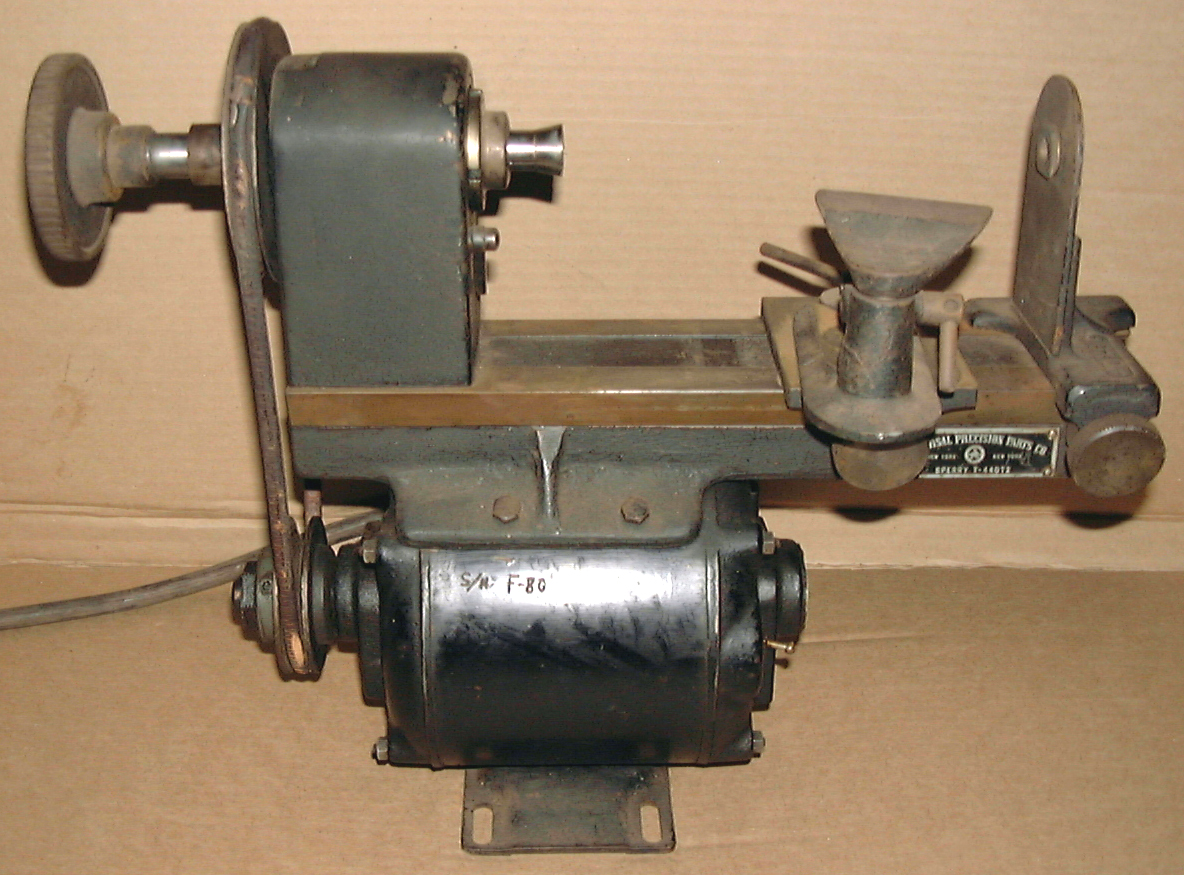
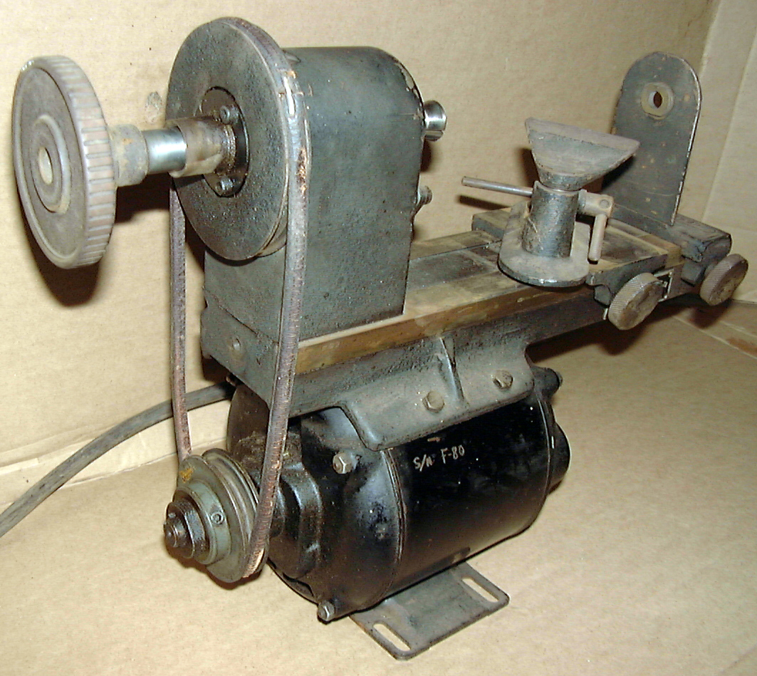
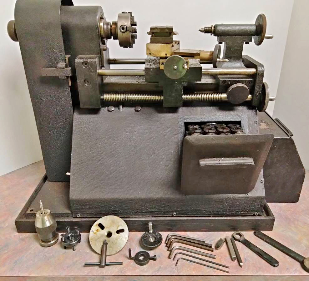
At least two versions of the lathe were made, the earlier being the T-44012 with a cast-iron bed with flat-topped ways, a simple (rather short) hand T-rest and a right-angle "tailstock/steady" that clamped to the bed's front and back surfaces, that at the front being flat and at the rear formed as a V. The drive motor, a conventional unit of about 1/2 h.p. with an attached switch, acted as the lathe's "foot" - the curved underside of the bed being bolted to its top surface. Although the T-44012 pictured below does not have a guard over its round leather drive belt, three is a tapped hole in the end of the bed that could have secured such a fitting. The headstock spindle lacked a threaded nose, instead, like many other precision lathes, it was machined to take draw-in collets, these being a "Size 3" with a maximum though bore of 0.5 inches. To lock the spindle while changing collets, a swing-up lever was positioned on the front face of the headstock that engaged into one of the four notches milled into the front bearing retaining ring. The later, rather different version of the Sperry was labelled T-44072 and appears to have used the same bed and headstock - though with the addition of a thread on the spindle nose and two steel bars mounted above the top of the bed and, along its front face, a hand-driven leadscrew. The bed bars and leadscrew were supported at the headstock end by the simple means of brackets bolted to its front and back faces and, at the other end, by a plate attached to the bed's end face. By these simple modifications, the lathe was made much more versatile and able to carry a screw-feed compound slide rest assembly, mount 3-jaw chucks, faceplates and other fittings on the spindle nose and accept a conventional tailstock - the spindle of which, in addition to a Morse taper socket, had an external thread to accept a precision keyless chuck. In addition, the lathe was also bolted to a cast-iron base plate and given sheet-metal covers over the drive belt and front and right-hand sides of the. A small drawer for collets was provided on the front face and, on the right, what appears to have been a built-on box to hold accessories and tools.
Despite these improvements, the lathe still had only one spindle speed, this being driven directly from the motor to a pulley overhung on the spindle's left-hand. With this severe limitation on its capabilities, the lathe must have been intended for a single, specialist task - though why a 3-step pulley was not used instead is a mystery.
Established by Dr Elmer Sperry in 1910, the Sperry Company became famous for the gyroscopes and other devices connected with ship and aircraft navigation. All the company's test and calibration equipment was labelled with a part number comprising a prefix "T" followed by a number, their "lathe" being coded "T 44012" and T44072". Honeywell bought Sperry many years ago and a recent search by a Honeywell employee through the Company's older microfilm and test-fixture database, together with conversations with other employees, drew a blank on details of the lathe; however, the machine can certainly be dated, by its appearance and the relatively short serial number, to be of pre-1950 origin, and probably much earlier. The purpose of its original function is another matter but, during World War 2, Sperry produced bomb sites, autopilots, gyrocompasses, etc., at its works in Long Island, New York. These instruments would have contained a steel or copper rotor suspended in die-cast magnesium gimbals - much the same construction continues today in gyros fitted to light aircraft. The right-angle "tailstock/steady" at the end of the lathe bed closely resembles the attachments still used to hold the ball races on the end of gimbal spindles, rather in the way that bench centres can be used to hold a balancing rig, and it's possible that this bracket was used to hold a bearing on which the end of an item to be machined (or tested) could spin. Should any reader be able to enlighten the writer further about the Sperry lathe, he would be very interested to hear from you.
Another example of the Sperry lathe can be seen here - modified, restored and in productive use..
|
|