|
Continued:
Saddle and saddle drive
A conventional lathe saddle requires a drive connection from the lathe mandrel. Usually a gear train from the headstock transmits power to a horizontal leadscrew running from the headstock to the tailstock end of the lathe bed. The leadscrew is carefully located so that it drives the saddle with the minimum twisting moment to the saddle (racking). Consider such a lathe using the leadscrew to drive the saddle to take a cut on a 1" bar in the chuck. The leadscrew, or saddle drive via the rack, pushes or pulls the saddle to overcome the force at the cutting tool. The resisting force at the cutting tool produces a twisting moment to the saddle. The saddle sliding along the lathe bed absorbs the twisting moment. If the fit between the saddle and lathe bed is very good the saddle will slide smoothly along the bed producing a good finish on the turned bar. If there is any slack between the saddle and bed, the saddle will be twisted until the slack is taken up. This action can result in the saddle twisting and releasing as it slides (walks) along the bed, the resultant finish on the bar mirrors this action. A long unsupported leadscrew is also prone to flexure due to the thrust. These conditions prevail whether the cut is towards or away from the headstock. In an ideal world the cutting tool would be pushed and guided in line with the cut reducing any twisting moment to zero. The fact that the headstock can be raised or lowered relative to the bed and leadscrew adds further complications, which are neatly avoided by using an electronic interface between the mandrel and saddle drive.
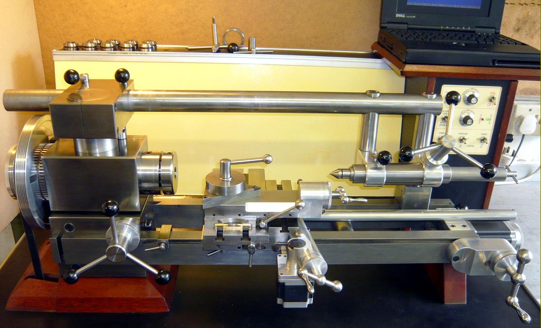
The Stepperhead saddle drive and control is located at the tailstock end of the bed and eliminates the need for an apron attached to the saddle. IMO an apron is only necessary to provide a convenient place to locate the saddle's mechanical controls especially on bigger lathes. An apron is also a dead weight added to the saddle, which offers no advantage to the machine operation; in fact its weight is detrimental adding higher bearing loads to the bed and adds a cantilevered load to the saddle. There is no need for the leadscrew to mechanically interconnect with the mandrel because this is done electronically. This avoids a lead screw having to run the full length of the bed and a gear train to connect to the lathe mandrel. Placing the leadscrew high and central minimises the racking effect on the saddle and is possible because the tailstock clears the bed. I think that if you tried to push the saddle along the bed with you finger this would be the best spot to push. To maximise the stiffness of the leadscrew it is fixed rigidly to the saddle and is as short as possible. The saddle drive thrust provision is also provided at the tailstock end of the bed. This avoids thrust provision at the saddle, which would be required for a rotating leadscrew.
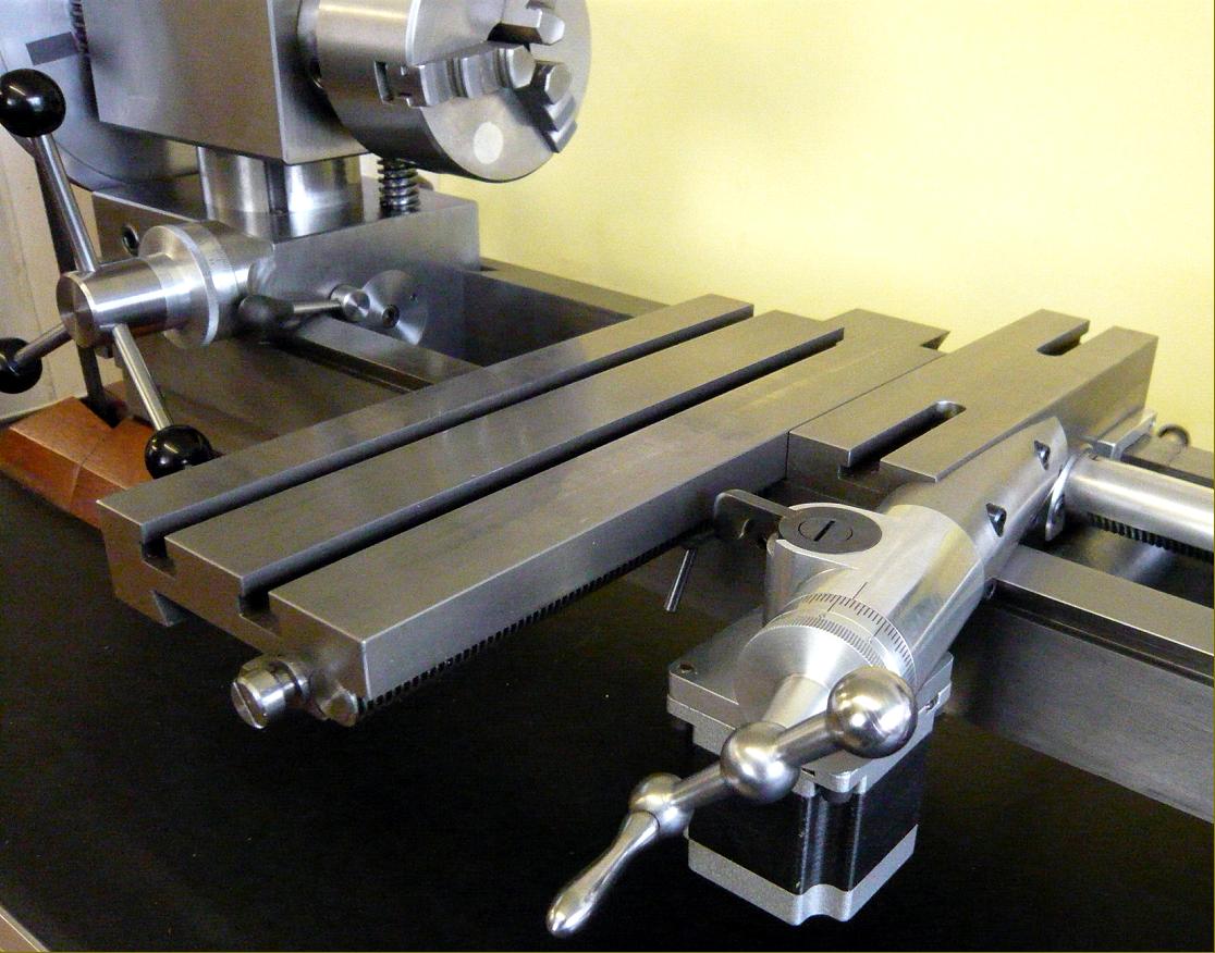
The saddle is narrow guided by the front bed way. The rear bed way only contacts the saddle on the rear dovetail and, of course, the top. The saddle can be moved by the geared down handwheel. A 1:8 ratio provides 0.500" movement for one complete rotation of the handwheel. The saddle stepper motor can be engaged or disengaged for automatic or manual operations. When the stepper motor is engaged the saddle can be manually fine fed via the incremented feed dial on the stepper motor when the motor is switched off, this is useful for setting up Z axis operations. The three gearwheels that give a 1 to 8 ratio at the handwheel will generate a small amount of backlash at the handwheel, but the mesh between the stepper motor worm and the wormwheel and the leadscrew to the wormwheel can be adjusted to minimise backlash in the stepper drive. The leadscrew guide bearing block can be shimmed to adjust the mesh and the fixing arrangement at the saddle allows the leadscrew to be centralised by this bearing. Two opposed, angular contact ball bearings at the stepper motor worm shaft absorb the axial thrust. Hopefully this design reduces inertia and start up forces of the saddle assembly, which assists the stepper motor drive.
There are alternatives to this design of course. The most likely could be a handwheel rotating about an axis parallel to the leadscrew driving a rotating a nut on the leadscrew by a toothed belt drive, which also is driven by the stepper motor. This nut would require the axial thrust to be dealt with. Or perhaps a ball screw could be used, choices?
My contention is that for manual operation it is good to be able to disengage the stepper motor for a more sensitive feel rather than have the additional drag of the motor magnets all the time. I know that it is perfectly possible to have manually operated handwheels generating pulses to drive the stepper motors but this requires the computer to be operational at all times and somewhat defeats the manual, power drive or full CNC alternatives of Stepperhead.
Cross slide
A conventional lathe cross slide is usually operated via a feed-screw moving the nut attached to the cross slide. The extent of travel is limited by the necessary location of the handwheel. The method used by Stepperhead is unconventional but offers some advantages. The free space under the tailstock allows a full width saddle, rather than the conventional wings each side of the tailstock and permits this design.
A non-rotating feeds-crew fixed to the side of the cross slide meshes with a centrally positioned worm wheel. The operating handwheel rotates a worm, which meshes on the opposite side of this wormwheel. Handwheel rotation rotates the worm which rotates the wormwheel to move the cross slide. The handwheel shaft and worm are located 10-degrees from directly opposite the cross slide feed-screw, so that the axes of the feed-screw and worm converge.
The wormwheel pivot position is adjustable between these converging axes to position the wormwheel for minimum backlash with the worm and feed-screw. The wormwheel pivot shaft is clamped to the saddle by two socket head screws accessible from underneath the saddle. When these screws are slackened the wormwheel is free to move between the handwheel worm and the feed-screw on the cross slide. Rotating the handwheel in a clockwise direction will cause the wormwheel to move away from the narrowing axes convergence, increasing the backlash. Whilst rotating the handwheel in an anti-clockwise direction causes the wormwheel to wedge between the narrowing axes, reducing the backlash. By manipulation the wormwheel in this manner the backlash can be set to a desirable minimum, then the pivot screws are then locked. However, the main advantage with this arrangement is that it allows unrestricted travel for the cross slide and positions the handwheel away from the cross slide movement. The 250 mm long cross slide can travel the full 250 mm. In fact the longer the cross slide the longer the travel. This is very useful for milling operations etc. A full length tapered gib is used to adjust the slide. It is slightly similar to the rack feed saddle drive on conventional lathes but has the advantage of being adjustable for backlash.
It is enclosed and well lubricated and the feed screw component sizes are maximised to reduce wear. The area of contact moving the cross slide is less than is available with a conventional nut and screw and this may prove to be a disadvantage with heavy use causing premature wear. These are early days and time will tell. It is dependant on the type of use that the machine is subject to. A conventional design using a fixed nut attached to the cross slide could also be used if desired but it will have a restricted travel.
Cross-slide stepper motor
The stepper motor drives a 20-tooth wormwheel mounted on the cross-slide operating shaft. The drive worm is fitted directly to the stepper motor so that one turn of the stepper motor will move the cross-slide 0.005". The stepper motor drive can be engaged or disengaged via the actuating lever, which rotates an eccentric sleeve. Using the stepper motor to directly drive the worm axially loads the motor bearings with the drive thrust. At present the motor bearings seems to cope very well with the small thrust they have to deal with and show no sign of complaint whatsoever. If pushed too much the motor armature could move axially overcoming a thrust spring retaining the motor bearings, but this has yet to happen. If in time it is shown that the thrust is too much for these bearings then separate thrust provision could be included but I doubt that it will be necessary.
This arrangement conveniently positions the stepper motor out of the operator's way and allows an unobstructed surface for the cross slide. A large metal sheet can be mounted on the cross slide because the stepper motor drive components are lower than the top surface of the cross slide. The motor power cable is contained in a tube under the bed, which moves radially as the saddle is moved along the lathe bed (a pivoting joint is located at the stepper motor) This keeps the cable protected and high under the bed for easy cleaning access.
Tailstock
Building the tailstock into the overarm has advantages in weight saving and rigidity by eliminating the need to slide and clamp the tailstock along the overarm. The tailstock can be moved along the bed when the clamps at the headstock and bed are released.
A clamp arrangement at the headstock would have still been necessary even if the tailstock slid along the overarm. The tailstock sleeve is made in cast iron. To reduce weight the cross members are made in aluminium and the vertical tubes in mild steel. The space below the tailstock body is clear and this enables the saddle to move under the tailstock, making more use of the bed length. The secondary vertical column can also be located in forward tube of the tailstock, to extend the maximum centre distance or maximise rigidity for milling operations.
The long tailstock barrel is a sliding fit in the mandrel bore, this feature is utilised to assemble and Loctite the tailstock components in position and in alignment. With the mandrel and overarm set parallel to the bed the tailstock components are Loctited together with the tailstock barrel inserted fully into the headstock bore. This ensures that the tailstock barrel is in line with the mandrel centreline. This requires that most of the machine is operational before the tailstock can be completed and sets out to some extent the construction schedule. This should not be a problem; it just sets the pattern of events. I still cannot think of a better way to ensure that the tailstock barrel accurately lines up with the lathe bed, overarm and mandrel without extensive machining facilities.
David Urwick's method was to machine the tailstock bore by boring the tailstock barrel using a boring cutter mounted in the headstock and pushing the tailstock by hand on to the cutter, and finally reaming the bore. I think that this would be difficult to control and give a good accurate finish to the tailstock bore. To be fair Loctite did not exist when he suggested his method so he probably did not have any other choice. The rack feed is sensitive for small drilling operations and equally powerful enough for large drills and allows quick easy retraction for clearing drill swarf. The rack feed easily deals with the long travel, which would become laborious with a screw feed. Another advantage of this design is that the tailstock barrel is always fully supported in its sleeve unlike screw advance methods whereby the tailstock barrel is only partially supported when fully extended. Morse tapers are easily ejected with the screw ejector at the rear of the barrel.
Main Motor
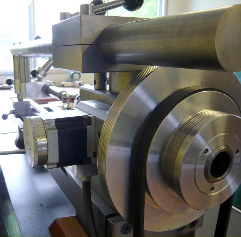
A 430 Watt 1400 rpm three-phase motor operates from 240v AC via a vectorless inverter. Modern aluminium body motors are light and powerful. This motor is dedicated to driving the lathe mandrel only. It does not have to drive gear trains, back gears, leadscrews, feedshafts and apron gearing for crossfeeds, which all absorb power, which is then not available at the mandrel. I chose this motor because it is the largest power size in frame 71. This keeps the motor weight and size down to acceptable limits, allowing it to be added on to the lifted weight with the advantage of keeping the belt tension unchanged when varying the centre height. The power output seems quite adequate. On/Off, Speed and Direction are all selected at the control panel.
Headstock stepper motor
Using a stepper motor to index the mandrel in conjunction with a separate milling head enables gear cutting, radial drilling, and spiral milling operations. The belt drive to the main motor can be left in place but it is probably better to remove it for these operations.
Removing the belt also disconnects this motor from accidentally being switched on and driving the mandrel when using the headstock stepper motor, which could damage the drive.
The stepper motor can be driven from the control panel or by the computer on its own as axis A or in conjunction with axes Z and X. The stepper motor worm drives a 30-tooth worm wheel, which drives a 20-tooth gear wheel meshing with the 60-tooth gear wheel mounted on the lathe mandrel. Ideally the worm would mesh directly with the mandrel gear but this arrangement permits housing the optical mandrel pulse sensor circuit board that enable screw cutting and inch/rev feeds as well. The gear mesh can be adjusted to minimise backlash. One turn of the stepper motor rotates the mandrel 4-degrees. The motor is set to 400 pulses/revolution; so each degree can be divided by 100. This seems quite fine enough but the stepper driver can easily be set for more pulses/rev if desired. An index wheel is provided on the stepper motor for manual setting, when the motor is switched off. The stepper motor assembly is moved up or down to engage or disengage the drive. The drive worm is fitted directly on to the stepper motor shaft so the same comments about thrust provision that are made about the cross slide stepper motor apply here. Except that the end of the motor worm can be set to just contact the surface of the headstock and this easily provides a thrust bearing in the forward rotation of the mandrel. If the thrust compensation becomes a problem it can be dealt with but at the minute everything is fine. I have machined a 38-inch long spiral slot (Spiral was one turn in 30 inches) in 3mm wall thickness 0.875" dia. mild steel tube and the mandrel drive stepper motor performed very well without any noticeable movement due to end thrust.
The motor belt can be positioned over the largest pulley only so that it does not drive the main motor and an eccentric cam located on the over arm can be used to lock the mandrel. This also biases any backlash in one direction. The eccentric cam can be locked in either direction and this feature can be utilised when doing repetitive dividing operations. Say in machining a 30-tooth gear wheel manually.
The computer is set to index the mandrel at 12-degree intervals each time the computer return button is pressed. The direction of rotation is set by a plus or minus sign at the 12-degree notation. The eccentric cam should be set so that it will automatically release when the next rotation is required. The rotation direction will then release the cam as it rotates; it is then pushed down to lock the mandrel for the subsequent operation. After which the return button is again pressed to release the eccentric and rotate 12 more degrees; relock the eccentric and so on until the job is completed. If the eccentric is locked in the opposite direction it is further locked by the rotation direction, which should be avoided because it will jam the mandrel and probably cause the stepper motor to loose steps and lose its position, which is totally undesirable. This sounds a complicated issue but it is really very simple and once observed quickly becomes obvious.
A single cable contains both the stepper motor control and screened pulse signal cables for the mandrel sensor. I had problems finding a suitable cable without buying a bulk reel. In the end I used a multi-core screened TV SCART (Peritel) cable that did both jobs admirably. I expected to have big problems with interference but it all works very well. This may be due to the fact that they do not both operate at the same time. I read on the Internet and elsewhere of CNC machines suffering horrendous, intractable problems due to interference from other motors and earth loops creating mysterious and unfathomable effects with computer control making stepper motors miss steps and was very wary about screened cables and earth loops etc. If the experts could not solve these problems how was I going to? I could not begin to know what to look for. All I could say is it won't go properly, knowing that I will get very little help because I am not blonde or the right sex, and too old. I must have been extremely lucky because I suffered none of these problems apart from having to grasp the mechanical/electrical/ computer interface and the jargon, which, are far from easy or obvious and you don't know what ask when the problems are new. However bit by bit it falls into place and even begins to seem logical. I think that you can only learn these things with practice, seeing what actually happens in response to the command you have issued to the computer. Confidence only comes when you know what will happen next.
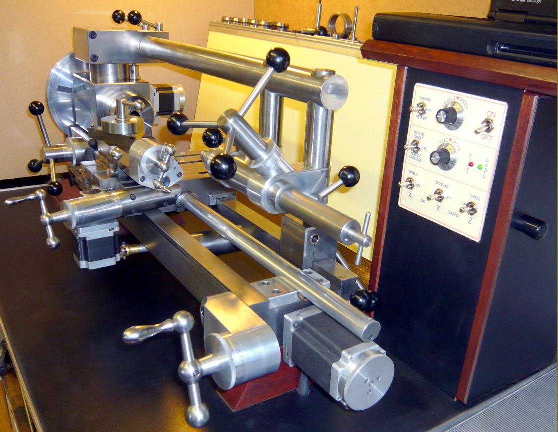
Control panel and computer mounting
The control panel and computer support box contains a Motion Control power supply and three stepper motor drivers in the lower section. Air circulation holes for cooling are provided in the back panel. It does not seem to get too hot even when run for long periods. The power supply seems to be able to deal with all three motors running with apparent ease. There is only space enough for three stepper motor drivers in the box. This is ok but it may be nice to add one more for say adding a stepper motor to the milling spindle in the vertical milling mode which, would be good for three axis CNC vertical milling, engraving etc. An extra stepper driver means a bigger box or it could be added outside at the back in some tidy manner. I have wired each stepper motor directly from the stepper motor to the driver avoiding plugs and sockets because I thought that they could be a potential source of trouble. However if a plug and socket is incorporated into the A drive only, it would be possible to unplug the A drive and plug it in to the Z drive motor on the vertical milling head when required. This would avoid adding a fourth stepper driver. The computer would have to be reprogrammed to suit but this in reality may only mean changing over the floppy disc and restarting the computer. This is how it could be done in Turbo CNC, with probably similar methods for other systems.
In the upper section is a pulse generation circuit board, which can supply a variable pulse stream for manual control of the stepper motors. For the circuit info for this board I am indebted to a very good article in Model Engineers Workshop No 118 by David Haythornewaite. I took his basic design and remodelled it to suit my requirements. The front panel switches connect either to this pulse stream or to the CNC pulse stream for each axis with an off option in the centre position. A break out board interconnects the input/output signals to a 25-pin printer port socket at the rear of the box. This enables the computer to be connected via a printer cable. Any computer with a printer port can be connected via this port. This should be noted because many modern computers only use a USB connection for printers.
Other switches on the front panel select the stepper motor forward or reverse direction for manual control with an off position in the centre. The pulse rate, which sets the stepper motor speed and therefore the feed rate, is controlled by a rotary potentiometer on the front panel. When the switches are set for computer only control of the stepper motor or motors the manual pulse circuit board is of course isolated. Well it is not completely isolated, the direction switch must be set to FWD otherwise this will override the signal stream from the computer. Failure to set the direction switch to the centre (forward) position when using the computer signal stream will override the direction control signal with disastrous consequences because the direction signal is rendered inoperative, meaning that the stepper motor will only drive in one direction it cannot change direction, so be warned. It is important to ensure that pulse and direction instructions can only come from one source at a time. It is imperative that the computer is switched off when doing manual control of the stepper motors and vice versa.
The main motor is also controlled at this panel via an inverter. I have not shown or located this inverter. I can be conveniently placed somewhere under the base board giving access to it's front panel. The motor can be switched on/off with one switch, forward or reverse on the other and a rotary potentiometer controls the motor speed. Placing the control panel and computer at the tailstock end seems quite convenient and positions the operator and computer away from the cutting operations. You may notice that the main pulley does not have a guard. If it is considered necessary from a safety aspect then by all means fit one. I have not suggested a design and there could be many permutations that are suitable. I did consider making one but it is very convenient to be able to handle the pulley for many small tasks and I think in my case the guard would be more often open than closed.
Computer
I have used a fairly old laptop computer that came my way, which runs on Windows 95. I do not think it would work with Windows XP so this somewhat limits the choice of CNC control systems available. I am using TurboCNC Version 4.01, which should only be run in DOS. TurboCNC say that the computer pulse signals are unreliable when operating through the additional load of a Windows operating system and this will result in missed steps etc. I had a struggle to get it working directly in DOS, it boots up through a floppy disc where it is reliable and does not miss steps. I am on a learning curve for CNC and up to now it fulfils all that I need. There are other CNC computer systems available some of which have a graphical interface showing the outline of the tool path and the shape being made. Mach 3 is one of these. I am no expert on this but there are web pages devoted to these systems and the system suppliers offer much help and advice on the requirements of computers etc.
Stepper Motors
There are two hybrid Nema size 23 motors 56 mm long (Holding torque 1.24 NM, 175 Oz-in) used for the head and cross slide and a size 23 which is 76 mm long (Holding torque 3 Nm, 425 Oz-in) motor for the saddle. These motors seem to supply adequate power. Motor sizing was a lucky guess based on information gleaned from similar applications. I do not think that larger motors are necessary. The stepper motor drivers have a row of small (dip) switches that can be adjusted for numerous pulse and current permutations to suit the application and I have set them so that each motor is just powerful enough for its axis. This provides a measure of safety because the motor will stall if overloaded. The stepper drivers can be easily adjusted to give more motor power and pulses/rev. The dip switches that set the amperage and pulses/rev are easily accessible for this and can be set as required. As mentioned earlier, I had difficulty finding screened 4 core cable in the small quantities needed so I used TV SCART cable. The separate screened cables were grouped into sets of 4 cables each (leaving some spare) for the connections between the drivers to the stepper motors. The connections for the mandrel sensor were also included in the cable to the headstock drive.
Splashback
This has been constructed from 6 mm thick MDF in a triangular shape which enables cables and low voltage transformers to be housed. The computer power supply can also be housed here. The cross slide cable is also routed into here via its protecting tube.
A plug and socket can be added for the "A" drive cable if desired. This will enable a stepper motor to be added to the milling head top-slide for three axes CNC. The "A" drive cable to the motor can be disconnected and the milling head stepper motor can be re-connected to the "A" drive stepper driver. The top shelf provides space to accommodate collets and chuck keys etc. A step or slide groove is also useful for a clipboard and to mount the milling head DC motor controller when it is used. A four-way power socket is mounted on the rear face out of the way of swarf, etc.
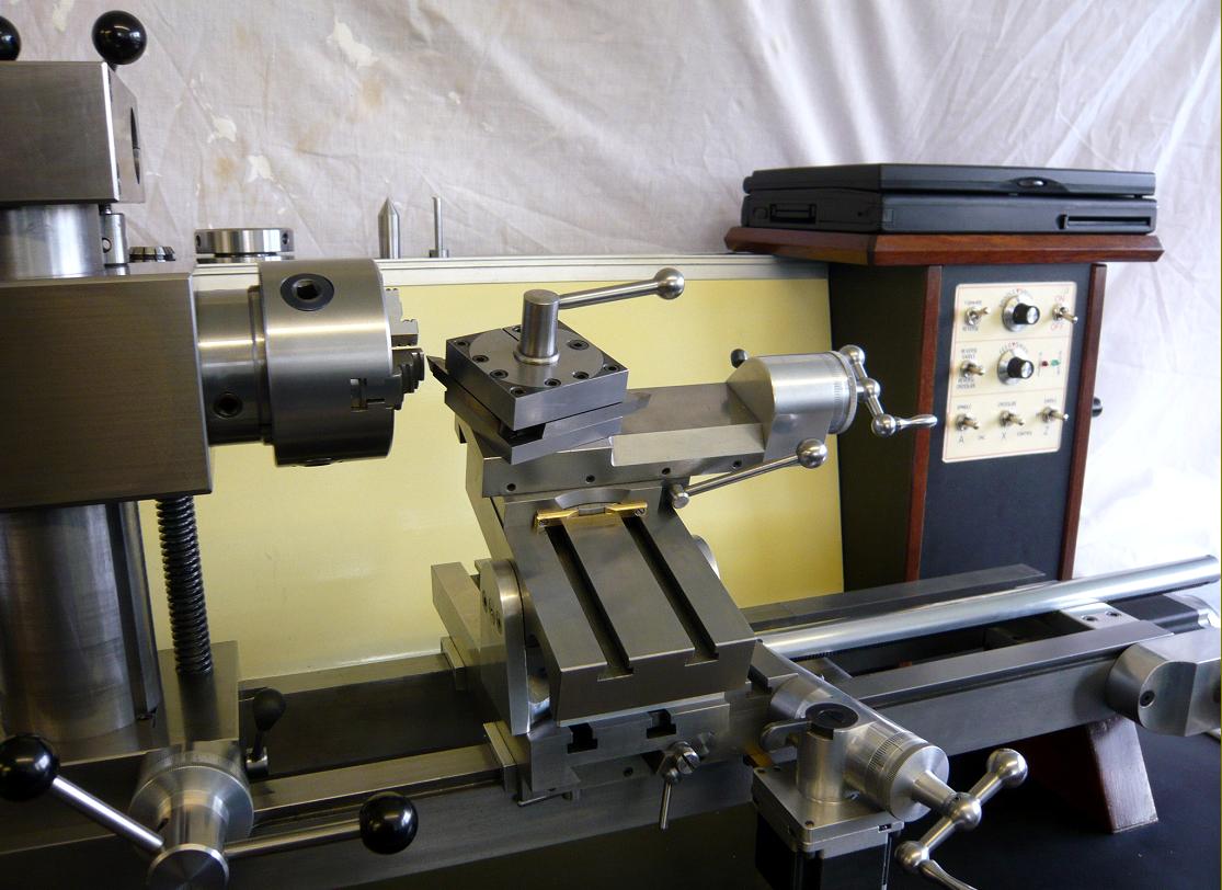
Top slide
The top slide features a lever locking arrangement enabling it to be positioned and rigidly locked at any angle anywhere on the cross slide. A screwcutting retract and toothed belt drive handwheel are also provided allowing a large micrometer dial with friction reset. The feed-screw nut can also be adjusted to minimised backlash. The slide has a total travel of 60 mm. The top-slide can be unlocked and moved anywhere at any angle on the cross slide. This has many uses, which are described later. It can also be quickly removed or replaced. An advantage of the tailstock design is that it has a clear space below the tailstock barrel and allows the top slide to fit closely up to the tailstock centre. The top-slide retract lever is also profiled to clear the tailstock.
Toolholders
I have made two different toolholders but any other design can be fitted as desired. Because the lathe centreline can be raised or lowered there is no need for height adjustment at the cutting tool. This permits simple rigid designs for toolholders with no cantilevered overhang so that the cutting tool is directly supported through the top slide and cross slide then directly down to the lathe bed. Consider a Dickson style toolholder, a carbide tip is mounted on a square toolbar which is in turn mounted in a dovetail tool mounting block and this is clamped to the toolpost body mounted on the topslide. This uses many clamped interfaces each of which can make problems and also results in a cantilevered overhang of the cutting tool. Carbide tips are directly mounted on the triangular toolholder for maximum rigidity. It is also possible to invert the toolholder using the circular spacer, which has a preset thickness to mount the inverted cutting tool at centre height. The advantages of a rear parting tool are well established so inverting the cutting tool can use these advantages for normal turning. I think this is especially important on small light lathes. The cutting tool can be positioned as a rear toolholder (the top slide will allow this). Or the lathe can be run in reverse with the topslide in the conventional location. This is useful for heavy cuts and for preventing or reducing swarf being sprayed everywhere. I also believe you get a better finish this way.
The square toolpost is designed for two 8 mm or 5/16" square HSS cutting tools, a parting tool and a boring tool. The various cutting tools are retained by large recessed grub screws, which also permit this toolholder to be mounted normally or inverted. So it also can be used as a front or rear toolpost as desired. I have found that a D bit mounted in the chuck is useful for cutting tool centre height setting.
Milling Head
The milling spindle is mounted on two large ball bearings and has a built-in drawbar, which also acts as an extractor for a No 2 Morse taper. The modified 24-volt 250-watt DC motor (Model MY1018 similar ones are used on motorised invalid chairs) can be mounted on either side of the milling head body. A polyvee belt drives the spindle via low or high speed pulleys. The DC power controller can vary the speed and the power cable can be fitted either way allowing forward or reverse rotation. Four M6 through bolts mount the head assembly using tee bars directly to the cross slide or mounting table. The square body enables easy setup alignment. The milling head assembly can also be mounted directly on the milling head top slide. For very fine work, engraving etc a Dremel style tool can also be used if a suitable mounting bracket is made.
Milling head Top slide
This slide is a modified and was a very battered early Myford ML7 top slide. The slotted radial bolt lugs were removed and, a lever locking arrangement fitted. The Vee-slides were cleaned up and the nut made adjustable to minimise backlash. A toothed belt drive at the handwheel, with ball thrust bearings added at the feed screw to ease the load on the belt drive. A dowelled cast iron profiled gib strip and a slide lock screw have also been added, replacing the original mild steel rectangular strip. The machined top slide mounting point is tapped for four M6 bolts to suit the milling head. Having an additional top slide just for the milling head could be considered somewhat of a luxury. It is perfectly possible to use the main top slide for both purposes by adding additional tapped holes for the milling head and removing the central bolt for the toolholder. However if it is planned to add a stepper motor to the milling head top slide then a devoted top slide may well be preferred.
Mounting Table
Normally a vertical slide is used to expand the operations possible on a lathe. A fixed mounting table is all that is needed on the Stepperhead. It can be set at any angle and is more rigid than a vertical slide because it avoids the adjustable dovetail slide; the elevating headstock provides the vertical adjustment. The table can be mounted in many locations i.e. on the overarm or on the cross slide via the vertical or horizontal columns. It can also be mounted on the lathe spindle as a faceplate by using the Camlock studded plate bolted to the rear face. The mounting plate is proportioned so that the faceplate assembly is balanced when assembled on the mandrel. The top slide, milling head top slide, milling head assembly and vice components can all be fitted as required.
Vertical and Horizontal Table mounts
These components enable the table to be mounted on to the cross slide as well as on the horizontal overarm. The table can be rigidly mounted at any desired single or compound angle relative to the mandrel axis. The variety of set ups possible with are very extensive.
Vice
While other vice and clamping arrangements can be used, this simple vice can provide a large to small capacity and be mounted at an angle to the tee slots on either the cross slide or mounting table. A small step in the clamp jaws allows items to be mounted off the table face. Its clamping force is limited by the grip in the tee slots but it is adequate for many operations.
Keyway Cutter
Being able to secure the operating lever pivot on the mounting table fixed to the overarm enables a direct connection to the headstock. This avoids the problem of the cutting force moving the cross slide backwards when the pivot is attached to the cross slide. It is also possible to mount the slide at almost any angle to the lathe axis. The Mandrel can also be indexed using the headstock stepper motor to create splines etc.
The example shows a 10-degree tapered spline fitting into a matched bore.
Collet Chuck
ER32 collets can be directly fitted in the lathe mandrel with minimum overhang using the Camlock chuck fitting. The tapered bore for the collets is machined in situ to guarantee concentricity. The collet-closing nut has 5/16" blind holes enabling a Tommy bar to close or open the collets. Conventional proprietary collet closing nuts have an eccentric portion inside the nut, which is clicked into the extraction recess on the collet to withdraw the collet to release the part being held. I have replaced this with two hardened steel washers fitted inside the closing nut enable the collet to be withdrawn, as the nut is undone. This is much easier to make and provides a hardened surface bearing on the collet extraction groove which has a somewhat rough surface due to the machined slots in the collet.
Baseboard
I mounted the whole machine on a baseboard of 1000 mm long x 600 m wide x 20 mm thick plastic faced chipboard. This was mounted on a bench made from a 40 mm square tube welded fabrication. I added two 40 mm steel angle strips running the full length underneath the baseboard to give added support directly under the lathe supports.
This bench and baseboard are very adequate but if I was to make it again I think I would choose a thicker baseboard just to avoid any resonance or vibration. Not that the existing arrangement is lacking very much but just because you can. Kitchen worktops provide just the right surface, are about 40 mm thick and can be easily found in most DIY shops. This would provide a non-resonant baseboard with good surface and not need additional support beneath the board.
Stepperhead Operation
I am still in the learning mode with Stepperhead but I can say that it works much better than I ever expected. I will go so far as to say it is fun to drive. It is surprisingly rigid compared to similar size lathes. I think headstock and mandrel add much to this.
I expected that the headstock being attached to the bed via the vertical column would be detrimental to the overall rigidity but I have not noticed it. Conversely one could argue that when the vertical column clamps are tightened it provides as rigid a mounting for the headstock as any conventional bolted arrangement. I have easily parted off 1" mild steel bar without any hint of distress or chatter and have purposely turned parts extended further from the chuck than is sensible with no hint of chatter. The saddle drive works very well, I can make a deep cut on manual or power feed and wind the tool slowly back without a fine additional cut being added due to spring (or saddle racking).
I am going to claim that this is due to the saddle drive leadscrew position moving the saddle without importing too much twisting moment although this is difficult to prove.
It is after all a test bed incorporating many untried and unconventional features and my first experience with CNC, stepper motors and electronic control. I have got used to the presence of the over arm, it does not seem to restrict or hinder operation. The gains in rigidity provided by the overarm being locked to the bed and headstock are quite palpable. The top slide can be moved anywhere on the cross slide. Full use of this is realised when say turning a steep taper. The top slide can be positioned so that the cutting tool is past the centre of the component being made and the lathe run in reverse. This enables easy access to the top slide handwheel whereas normally the top slide will be positioned awkwardly close to the chuck. One is spoilt for choice here because this same operation can also be done with CNC control by setting the X and Y axes to move in unison to generate the same taper at a controlled feed rate if required. Being able to control the mandrel speed and cutting feed during operation is also very convenient. Deep cuts and fine feeds can be set to achieve a good finish.
The elevating mechanism seems to be able to do it's lifting without too much effort. Subsequent dismantling showed that the rubbing surfaces of the worm and wheel were quite ok. The Z and X axes operate smoothly and give a good finish in manual mode and even better finish in manual controlled stepper drive. There is not much need to change the belt position, the middle pulley size covers the speed range from 100 to 2200 rpm, which is suitable for most operations, but screw cutting is best done on the biggest pulley at about 120 rpm because the additional torque keeps the speed more constant. The more constant the speed in screwcutting means that less acceleration/deceleration is demanded by the system to keep the thread pitch constant.
In some operations it seems advantageous to use a combination of CNC and manual inputs. For instance screw cutting using the computer to control the thread pitch and length and set the cut depth and withdraw manually. This is not full CNC, which can also be done, but perhaps, a model maker's one off pragmatic version avoiding extensive programming and set up. This does not restrict full CNC in any way; it is just that it is an easy, useful option, which is only available due to the ability to mix manual and CNC operations.
CNC operates in either, 'Absolute positioning' which always starts from a preset zero position or 'Incremental positioning' which moves a set distance from the existing position with no reference to any home or zero position. Certain operations require either ABS or INC mode. For most of my operations INC seem preferable. It is very necessary to be sure that you are in the correct mode; failure to do so can give undesired and unexpected movements to the axes which can be quite disconcerting.
I have set up for imperial units but metric can also be chosen.
In Turbo CNC there are two operating modes. The first is preset program control whereby the control instructions (G codes) are prewritten programs that can be recalled and used or copied and modified to suit the desired operation. The second mode is called MDI (Manual Data Input) whereby a single line of control code is keyed in and the instruction is then applied. This all soon becomes quite obvious but it must be carefully carried out. The machine will only do what you instruct it to do. Tell it to do wrong, it will.
As an illustration here is a simple example of incremental MDI mode. Tan 5 degrees = 0.0875. Type in G01 Z-1.000 X0.0875 F0.001 then press enter and it will move the saddle 1" towards the headstock and simultaneously move the cross slide 0.0875" away from the lathe centreline at a feed rate of 0,001"/rev. Which will machine a taper of 10-degrees. When the cut has finished change the input to G01 Z1.000 X-0.0875 F0.001 (Positives and negatives reversed) press return and the tool will move away from the chuck following the taper. These figures can be varied at will to produce an infinite range of tapers (Morse 1, 2 etc) and feeds without having to carefully set the top slide at the angle required. I am certainly not an expert on CNC control. So I will avoid trying to teach a subject I am just beginning to grasp. I just wanted to convey the advantages available to the home workshop.
I have found that using MDI mode with a manual override suits many of my requirements. What this means is, to machine the pre-described taper and be able to manually set the cut depth by using the top slide set at 90-degrees to the lathe axis permits a degree of manual control over pure CNC operation. The computer generates the taper and the amount to be removed is controlled by the operator.
Screwcutting is another operation, which becomes easier with computer interaction.
I use the word interaction purposely, because full CNC control requires careful and extensive set up to achieve the final result from a piece of bar stock to the finished item and if you are only going to produce one item it will consume a vast amount of precious time. Well it does for me. MDI mode will allow any screw pitch for a chosen length to be cut. By using the top slide set at say 27.5-degrees (for Whitworth thread angles) the thread depth cut can be set for each pass using the top slide. I set the speed at about 120 rpm (the screen gives a readout of the mandrel speed).
The tool will then cut the screw thread to the length chosen and stop, finishing the thread with a cut depth undercut; because the tool stops moving but the mandrel continues rotating. The tool is then manually withdrawn using the withdrawal lever on the top slide. This avoids the instant disengagement of the half nuts, before the tool hits a shoulder, which is necessary on a normal lathe and a genuine source of panic and fear. To rewind the saddle for another cut the MDI input is modified by changing the Z-axis from minus to plus on the computer, hit return on the computer and the tool will return to the start position for a new pass. Reset the MDI Z axis back to minus, return the top slide withdrawal lever and set the new cut depth for the next pass then hit return again. Do this as many times as required until the thread is finished. This may sound like an involved process but I am sure once observed it will seem a lot less complicated than the procedure on a manual lathe.
Left-hand threads can be cut in the normal manner by starting the tool close to the headstock and moving away from the headstock with normal anti-clock rotation or by using clockwise rotation with the cutting tool on the far side of the lathe mandrel and moving the tool towards the headstock. The advantage of this is that it is not necessary to make an undercut to the thread depth to start the cut from. Also CNC threading requires a small distance at the start of each cut to get synchronised with the lathe mandrel so an extra length needs to be added for this. Any backlash in the drive is pre-compensated for in the computer set-up.
What I have described above has been my approach and findings so far and should not restrict or limit the use of the many other options possible, which are available with CNC control. The lathe mandrel was set at 5-degrees to the bed axis. I choose 13.5 TPI because you can. There is virtually no limit or restriction in the pitch selection. No need to select complex gear ratios between the mandrel and leadscrew it is all easily dealt with by the computer. Just type in the desired pitch and thread length. This would be an awkward set up on a conventional lathe but simple with CNC and Stepperhead.
In full CNC mode the Z and X axes can be programmed to make simple to complex shapes repeatedly. Positive and negative curves etc I am still in the learning mode here. Once a program has been made for a particular component it can be saved and reused again. It can also be copied and modified to make a new similar program. So a library of programmes can be built up for future use.
Milling
Horizontal or vertical milling cutters can be mounted in the lathe mandrel and the part to be machined mounted directly on the cross slide or on the mounting table via vertical or horizontal columns. The lathe mandrel is more rigid than the milling head and should be the first choice for heavier operations. Horizontal milling cutters can also have additional support from the tailstock. There is 120 mm vertical travel from the elevating headstock, 250 mm travel on the cross slide and an excess of 300 mm travel along the bed.
Using the milling head mounted on the cross slide either directly or via the mounting table enables the lathe mandrel to be used for dividing; driven by its stepper motor.
The milling head can also be attached to the table mounted on the over arm forming a vertical milling machine. One advantage of this mounting arrangement is that there is no restriction in the X direction travel. The spindle to vertical column distance (Throat) limits the X travel in normal milling machines. Vertical adjustment is provided by either, the elevating headstock or milling head vertical slide. At present only manual vertical adjustment is possible but by providing a stepper motor to drive the milling head vertical slide would enable CNC three-axis control for vertical milling.
Grinding
Using a diamond wheel in the milling head turns the machine into a cutter grinder.
End mill ends etc. can be sharpened using the stepper driven mandrel to index the endmill. The saddle moves up to a preset bed stop. Horizontal milling cutters can be sharpened in a similar manner. It is also possible to sharpen end mill flutes by combining the Z and A drives to follow the flutes. X is programmed to move the wheel away from the endmill at the finish of the flute and returned at the start of the next flute. The slides should be protected from grit with newspaper when doing this.
Conclusion
At the 2008 Model Engineer Exhibition Stepperhead was awarded a Gold Medal and the Bowyer-Lowe Trophy I am proud to say and perhaps this also indicates that such a machine could fill many requirements for model makers etc.
So now a period of operating is needed to test and explore its capabilities.
As stated earlier I have a Colchester Chipmaster lathe and a Senior milling machine both of which are in good order and modified to suit my needs. So where does the Stepperhead fit in? It cannot compete fairly with these much more massive machines.
It weighs approx 130 kg against a total of 1000 kg for the other two. But it can in a reduced capacity do nearly all that both of them can do in one machine. It can also do many tasks that neither can do. To be able to machine a component at one chuck setting avoids errors in transferring from one machine to the next and saves secondary setting up. The computer replaces the gear train and gearbox that normally drives the saddle and cross slide. The choice of feeds, screw threads, tapers etc. is infinite and instant. The stepper motor driven headstock makes dividing easy and error free.
The requirement for countershafts, clutches, back gears, lead/feedscrew gear trains, screwcutting/feed gearboxes, tumbler reverses and jockey pulleys are eliminated.
This allows the main drive motor to drive the mandrel only; smoothly, quietly, without power loss and unwanted inputs from ancillary drives, which can and do affect surface finish. The Taper-roller headstock is grease-lubricated avoiding constant attention.
Both the Senior and Chipmaster are sturdy manual machines that can perform a range of tasks especially with a few purpose built attachments but this in my opinion does not negate Stepperheads contribution. I have already found many tasks that can be done on the other machines but are more easily and quickly carried out on Stepperhead. It is a very useful addition to my and I hope to your workshop.
There are of course alternative permutations of this design; for example, it would be quite feasible to fit the horizontal overarm and integral tailstock to a conventional fixed-head lathe. This would provide a horizontal arm to mount a milling head allowing the cross slide full movement, avoid the saddle being notched to clear the tailstock and enable more use of the lathe bed. The Stepperhead leadscrew, saddle and cross slide configurations could also then be used with advantage. The fixed-height overarm/tailstock assembly would also add stiffness to the headstock and bed - all good things for lathes.
There is an accepted convention in naming the particular axes in CNC nomenclature and I do not think I have followed this to the letter. I believe the mandrel drive should strictly be termed axis C in the lathe format. As a vertical mill the X & Z axes should change to X & Y. This will only matter if standard programs are used or transferred to other machines etc
Test samples
I have made these to show off my limited CNC prowess so far.
The wooden candlestick shape has a 2.4" sphere, tapered spiral column and a decorated base all made via CNC. The base underside has an inverted, 15-degree tapered spiral scroll.
The 10-degree tapered thread and nut is 13.5 t.p.i. Whitworth
The four-hole, white-plastic sheet was bored using the Manumatic boring head in conjunction with a Z drive at 0.002"/rev and 0.004"/rev. The X drive was also operating on three holes to offset the taper.
I have added some video files on Youtube; however, as I am a terrible camera operator so I ask you to forgive me for this.
Taper Turning http://www.youtube.com/watch?v=Yiug1F8XCME&feature=user
End mill Flutes http://www.youtube.com/watch?v=yMxv1jU-R_A&feature=user
End mill End http://www.youtube.com/watch?v=FDNTeuojC78
Gear cutting http://www.youtube.com/watch?v=wNxgWhizX54
Spiral milling http://www.youtube.com/watch?v=DMmDCHkff0c&feature=user
Happy Birthday http://uk.youtube.com/watch?v=sCsZN8Spbq8
Specifications
Centre height: Min. 80 mm Max. 205 mm (over bed)
Radial swing over cross slide: 45 Min. 170 Max
Max. diameter swing over bed: 410 mm (Over arm removed)
Distance between centres: 450 mm Max.
Spindle bore: 25.4 mm
Tailstock bore: No. 2 MT
Tailstock travel: 125 mm
Cross slide travel: 250 mm
Top slide travel: 60 mm
Motor: 430W 3-phase 1400 rpm nominal
Belt Length/Size: PJ belt 1245 mm, about 14 mm wide.
Spindle speeds: 15 to 3200 rpm forward and reverse
Weight: 130 kg approx.
Size: 1000 mm long x 600 mm wide x 500 mm high above bench
300 mm below bench for motor
Milling head motor: 24V DC. 250W Model MY1018
Speed range: 1000 to 4000 rpm approx.
Belt Length/Size: PJ 280 mm long, 4 ribs (3 grooves) 10 mm approximate width
Milling head spindle: No 2 Morse taper.
|
|