|
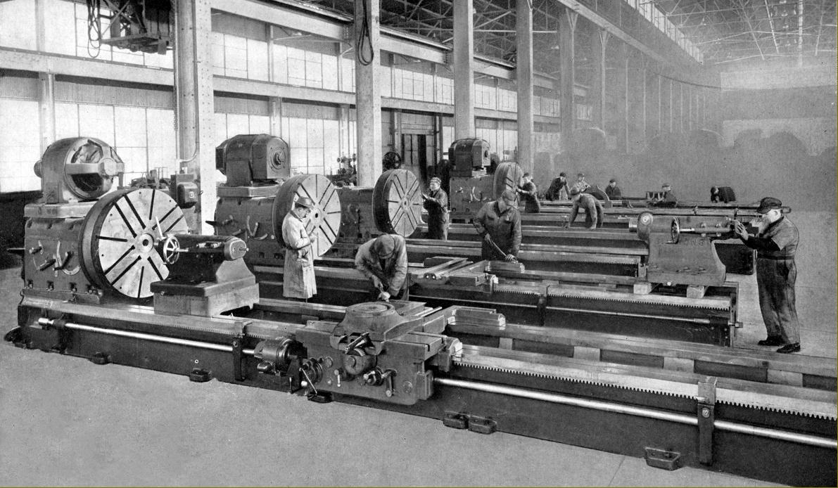
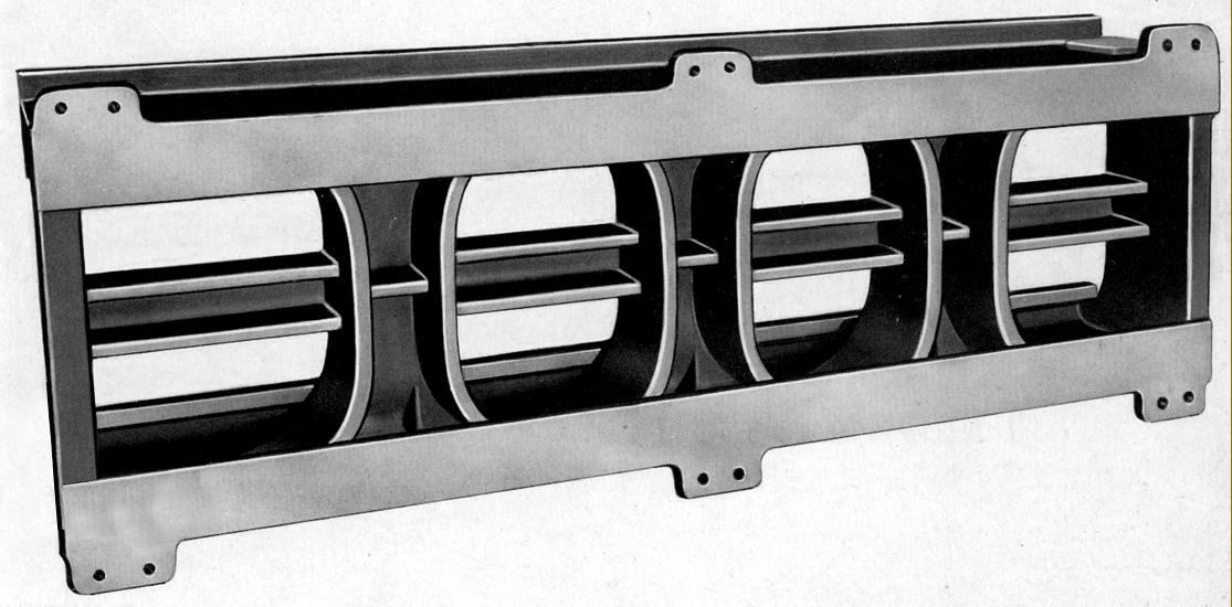
Now part of the Niles-Simmons- Hegenscheidt Gmb Group, the Simmons Machine Tool Corporation (http://smtgroup.com/) of Albany, New York, have long been established as makers of large, specialised machine tools - especially those for the railway industry. Established in 1910 as rebuilders of large lathes, today they make state-of-the-art CNC machines to do the very traditional jobs of railway wheel-set maintenance and production - machining that would originally have been done on either large conventional lathes or ones specially built for the purpose (examples of the latter by the German firm Deutschland Dortmund can be seen here). Manufactured during the 1940s, Simmons 48 and 54-inch swing lathes were the result of several decades experience dismantling, analysing features and rebuilding lathes from other makers. Advertised as being intended for use by: railroads, shipyards, ordnance plants and other large industries which perform extra heavy metal-working operations, customers were free to specify a bed of any length that they desired - this being cast from iron having a high percentage of scrap, nickel-content steel that produced a fine-grained surface to a hardness of Brinell 240. Of massive proportions and 42-inch wide, the bed carried flat ways and was built with front and back walls 24 inches deep, a minimum of 1.5 inches thick and braced by double-walled webs of an oval section, the whole assembly being a wide and very rigid structure. Cast as part of the bed was a central rack that allowed a pawl, fitted to the tailstock, to provide a solid lock when particularly arduous work was being undertaken. When equipped with a bed 20 feet long the all-up weight was, depending upon the headstock fitted, between 40,000 and 42,000 lbs (over 16 tons).
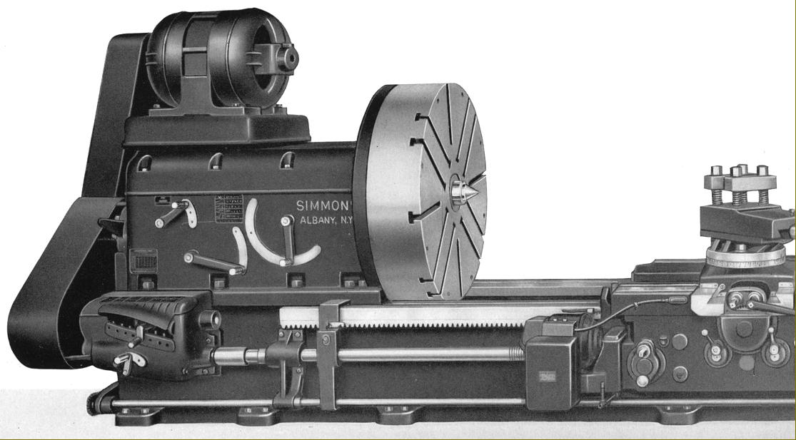
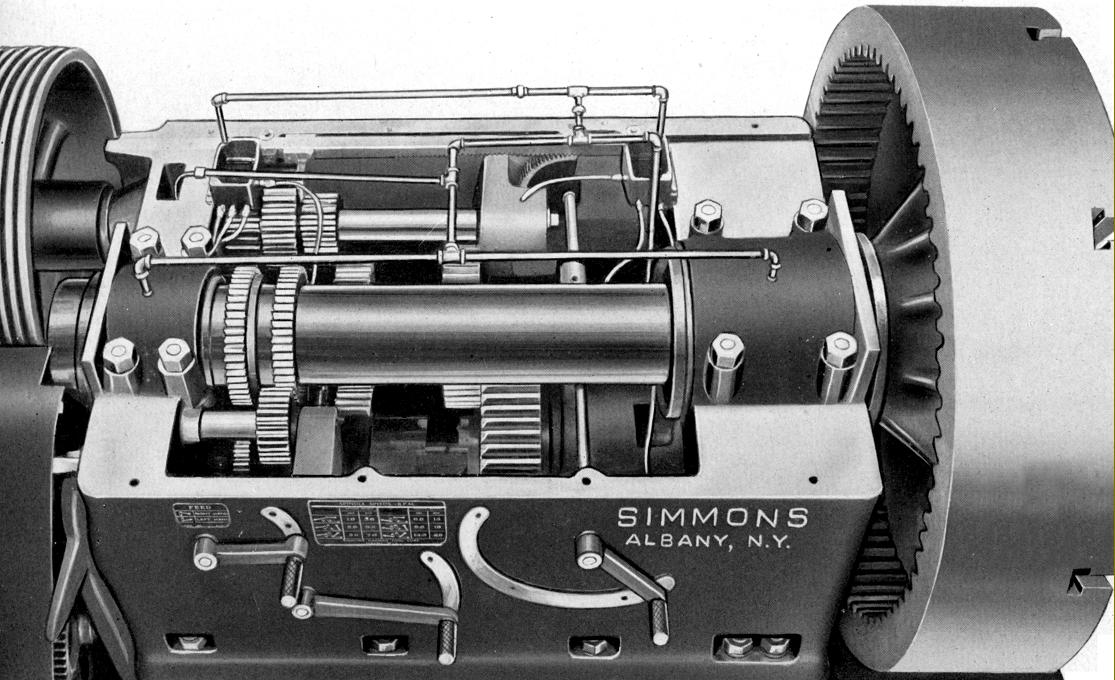
Of a straightforward but rugged design, the 56-inch long headstock was bolted to the bed and held a main spindle bored through 2.75", with a No. 7 Morse taper socket and made from a hammered steel forging that had been heat treated and ground to final size. Plain bearings were used, that at the front 9" in diameter and 15" long, that at the rear 5.5" in diameter and 9.625" long. Others shafts and gears within the headstock were in a heat-treated, SAE 4640 alloy steel and lubrication by a pressure pump feeding oil through a filter and strategically placed pipes.
A choice of either a 4 or 6-speed headstock was offered, both dimensionally identical but with the 4-speed driven by either a 400 to 600 r.p.m. (variable-speed) DC motor that gave final speeds of 1.6 to 50 r.p.m. or a 500 to 1500 r.p.m. DC motor that produced a range from 2 to 48 r.p.m. The 6-speed headstock was offered with a choice of four motors: a single-speed 900 r.p.m. A.C. that gave speeds from 3.6 to 29 r.p.m.; a single-speed 600 r.p.m. A.C. that gave 2.4 to 19 r.p.m.; a 2-speed 1200/1600 r.p.m. A.C. that gave 2.4 to 38 r.p.m. and a 2-speed, 900/450 r.p.m. A.C. that produced a final range from 1.8 to 29 r.p.m. Motor power was recommended to be between 30 to 50 h.p. depending upon the lathe's intended application. From a catalogue picture showing gearing cut into the inside rim of a chuck it appears that the lathes might also have been offered with a "triple-backgear" to provide even slower speeds - an example of this mechanism can be seen here on a Fay & Scott lathe.
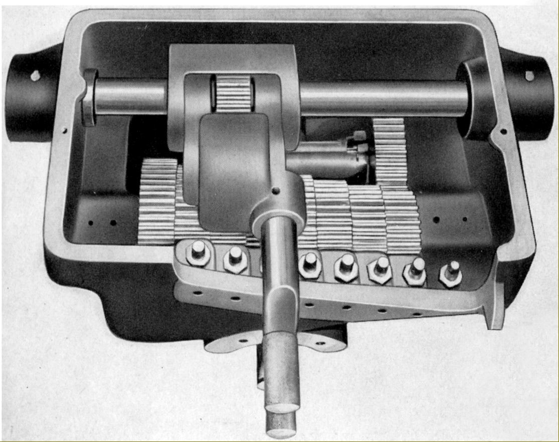
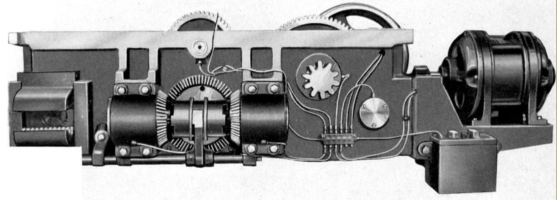
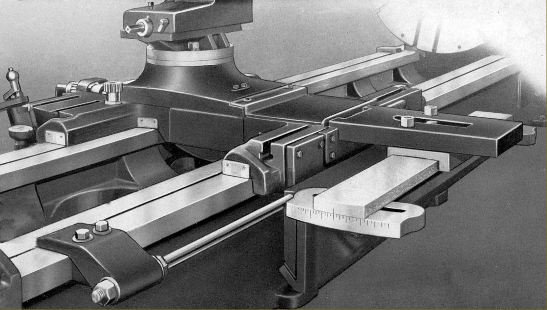
Sitting on its flat ways, the 60-inch long saddle (or saddles, as more than one could be provided) was gibbed to the bed at front and rear and carried the cross slide on its centre line, so giving maximum support to the cutting tool. A screwcutting and feeds' gearbox was provided as part of the standard specification that gave not only sliding and surfacing feeds to the carriage but also power feed to the top slide. "Rapids" was also available, driven from a separate motor flange mounted to the right-hand face of the apron.
Driven by a 1 15/16" diameter, 2 t.p.i. Acme thread leadscrew, the 32 screwcutting pitches ranged 1 to 14 t.p.i. with 32 sliding feed rates from 0.006" to 0.505" per revolution of the spindle and power cross feed at half that rate.
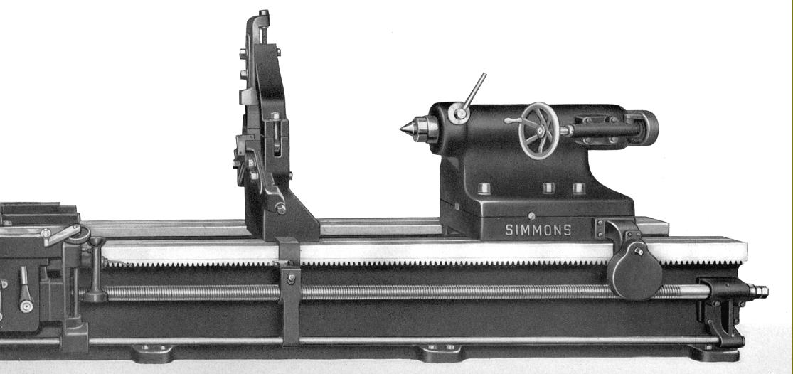
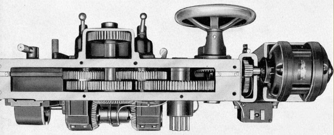
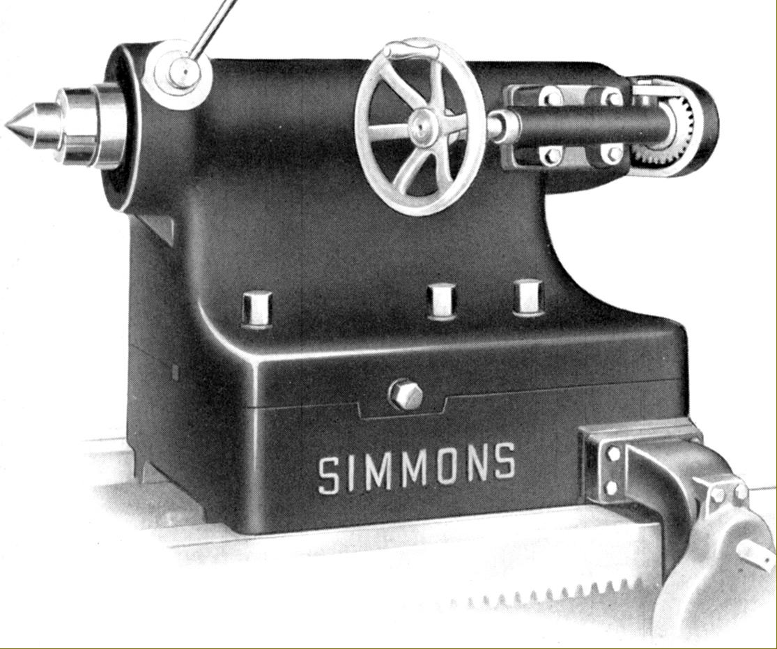
Heavily built, as might be expected, the tailstock was equipped with a 6-inch diameter, 20-inch travel spindle made from a ground-finished, high-carbon steel forging. It ran in precision honed bore and was clamped by an arrangement that promised no misalignment as it was tightened. Travel was by hand, the operating wheel being set at the front for the operator's convenience with the drive passing by gears across the end face to a large diameter screw that ran through a bronze nut. The tailstock body was clamped to the bed by four bolts, and further restrained by the previously-mentioned pawl that engaged against the bed's central, cast-in rack Able to be set over for the turning of slight tapers it was, because of its weight, moved along the bed by reduction gears that turned a pinion engaged with the rack also used to move the carriage by hand.
Lathes came equipped with a 4-stud, heavy-duty toolpost, headstock and tailstock centres, a "No. 1" steady rest to accommodate work from 6 to 18 inches in diameter, the motor base unit (but not the motor), drive pulleys, the necessary V-belts and guards and the operating crank handles and wrenches.
Amongst the extras available were steady rests of various capacities, second carriages, a motor-driven rapid traverse attachment, mechanical and electrical controls built into the apron (handy for the very long-bed models), taper turning, jaws to convert the faceplate into a slim-line 4-jaw chuck, front and rear toolposts and coolant pumps and piping..
|
|