|
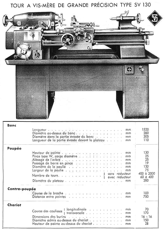
Home Machine Tool Achive Machine-tools Sale & Wanted Schaublin SV-130 & SV150 Built in the usual, no-compromise Schaublin fashion, the backgeared and screwcutting SV-130 and SV150 models were in production from the early 1930s - though by 1938 the SV-150 had disappeared from the catalogues as had, by 1946, the SV-130. It appears that the lathe was built in fout versions, the Mk.1, Mk.2, Mk.3 and, finally, With a centre height of 130 mm (SV-130) and 150 mm (SV-150) and admitting 750 mm between centres, the lathes were, despite their centre heights, mechanically identical. However, although the SV-150 remained unchanged though its relatively short production run, the SV-130 was to built in four versions. The first, the Mk. 1 (like the SV-150), was intended for drive by either a line-shaft system or from a built-on electric motor. In the former case the flat-belt-driven, speed-change gearbox was mounted low down on the outside face of the headstock end cast-iron leg while in the latter the belt pulley was replaced by an electric motor making the lathe self-contained. The next version, the Mk. 2, was fitted with a distinctly different headstock with a long, gradually tapering top and spindle drive by three V-belts. The lathe was carried on two substantial cast-iron plinths with that at the headstock end carrying an electric motor flange mounted against the outside face with the drive passing across to a speed-change gearbox fitted against the inside face - the box having an improved, 3-lever-operated control system. The tailstock-end plinth was arranged for storage, with a hinged cast-iron door. The penultimate model, the Mk. 3 (probably introduced during 1939), looked almost identical to its forerunner except for yet another redesigned headstock - the previous rather ungainly-looking, humped-backed type being replaced by one with a long, almost torpedo-like appearance. A very rare machine, the Mk.4 was carried on a more modern-looking sheet-steel cabinet stand, had a modified screwcutting gear box topped by two rotary controls and was fitted with infinitely variable speed drive. |
|
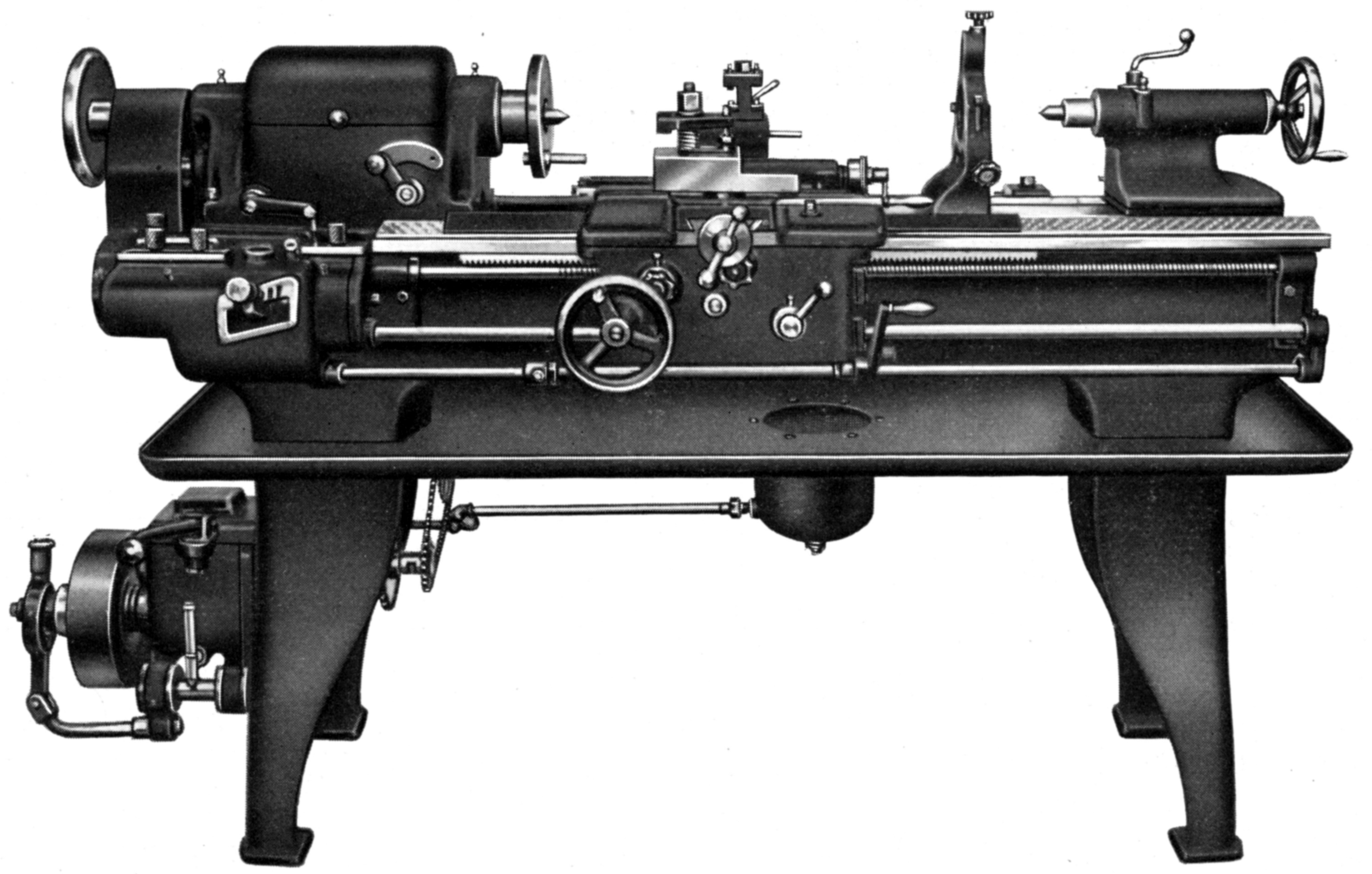
Schaublin SV-130 Mk. 1 as sold during 1933 and fitted with flat-belt pulley on the input shaft of the speed-change gearbox - the drive coming from a separate line-shaft system. The option was also offered on a built-on electric motor to make the lathe self-contained.. Note the open tumbler slot in the screwcutting gearbox |
|
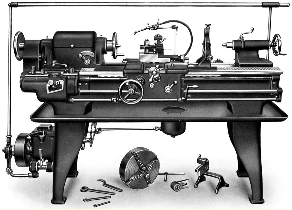
Schaublin SV-150 Mk. 1 as offered during the early 1930s. This version has a clutch bar travelling the length of the bed - a fitting that found some favour with other makers during that era |
|
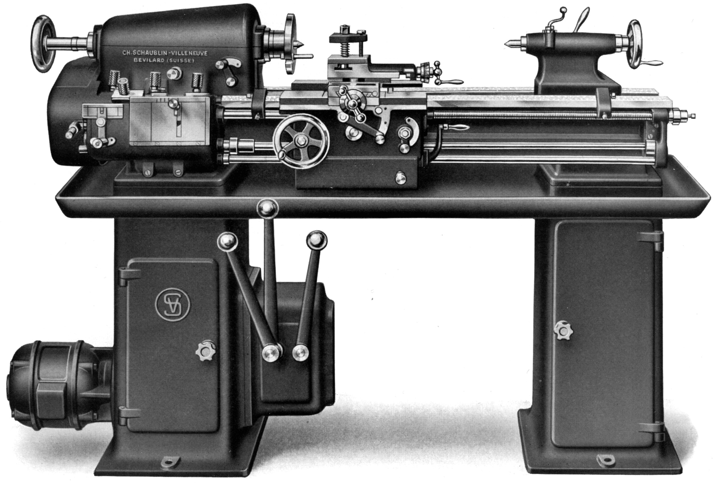
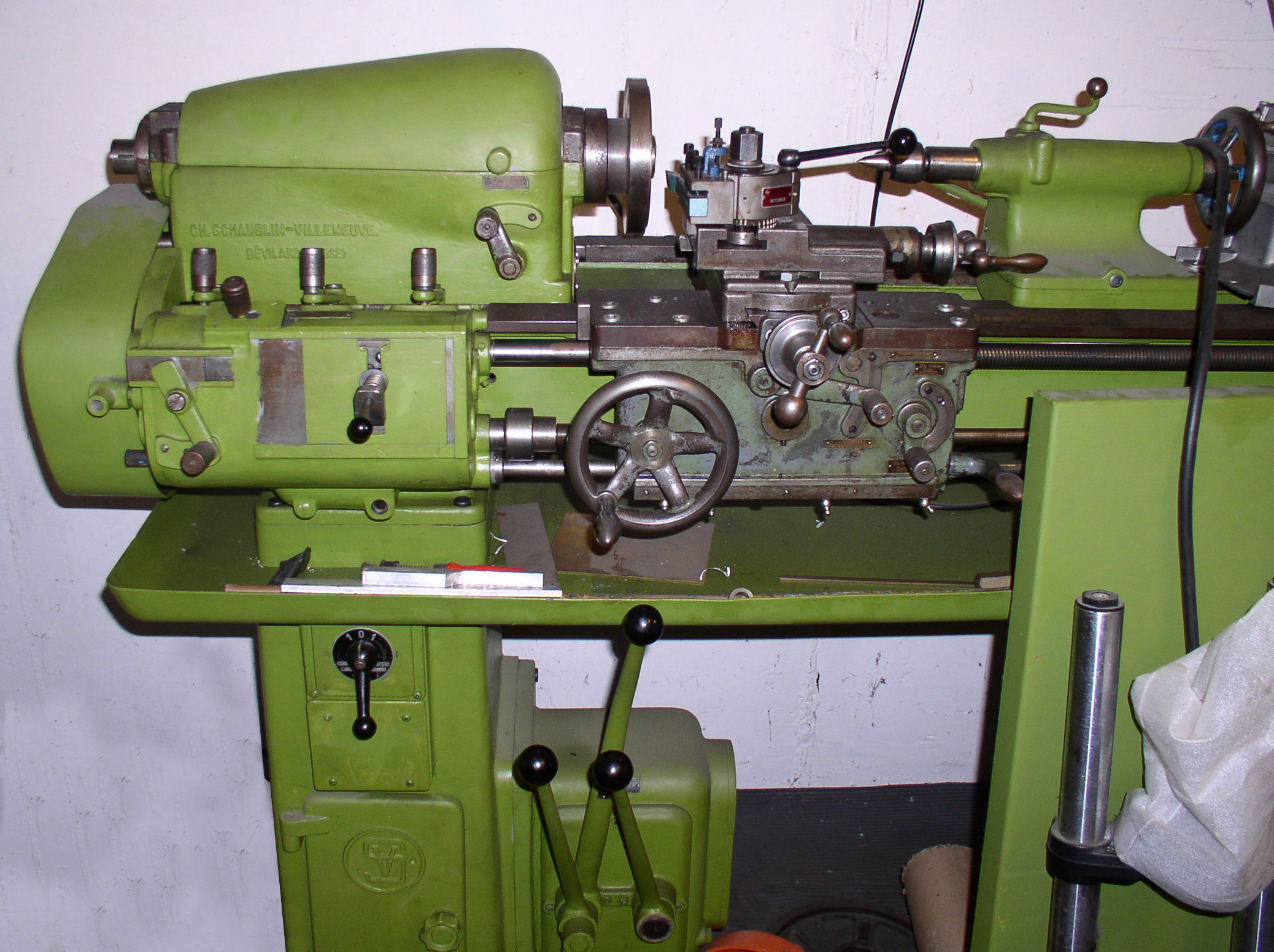
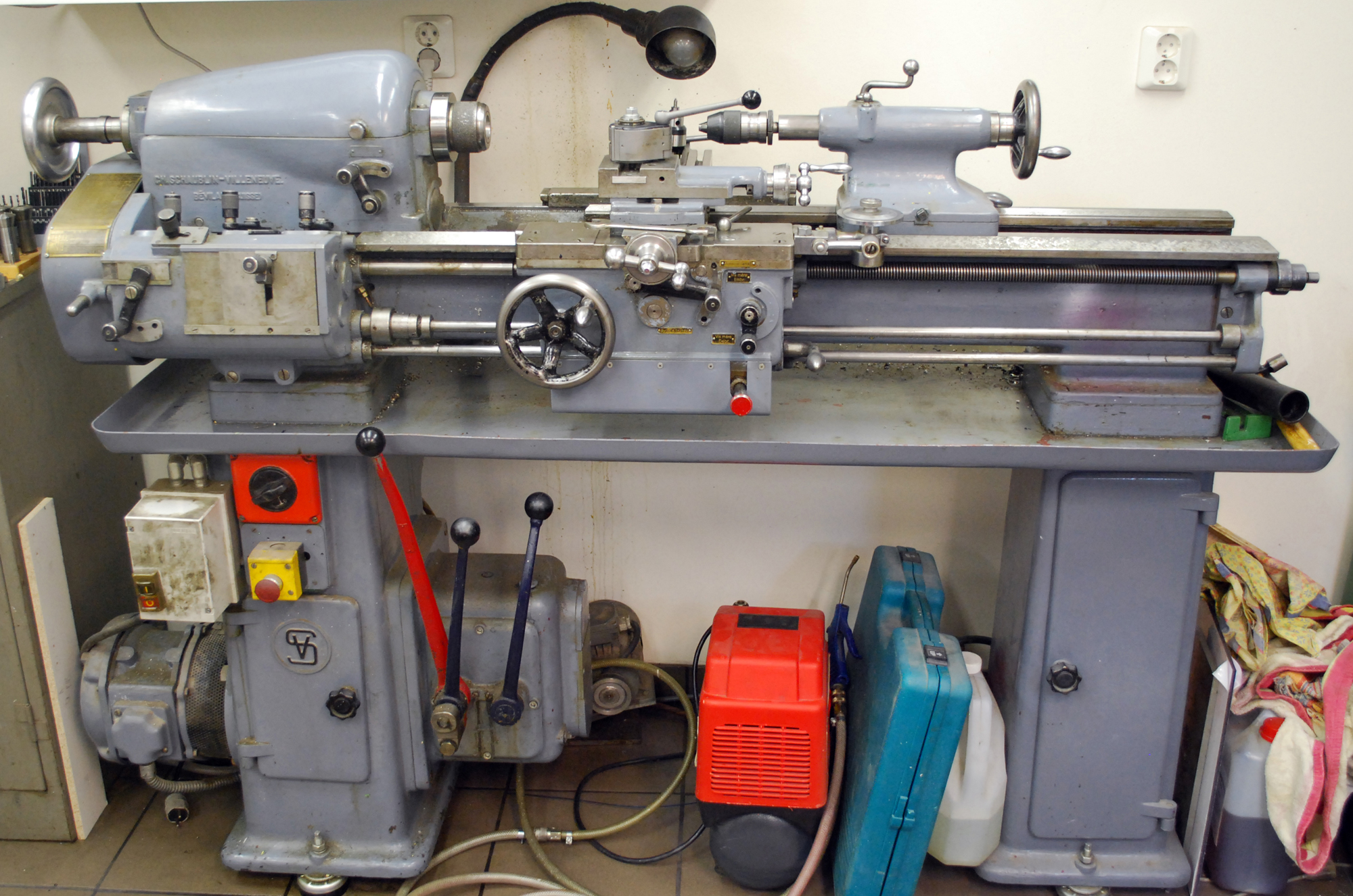
Schaublin SV-130 Mk. 2 as advertised during 1938 with a 130 mm centre height and 750 mm between centres. Note the now semi-sealed screwcutting gearbox and flange-mounted motor driving across to a 3-lever speed-change gearbox |
|
|
|
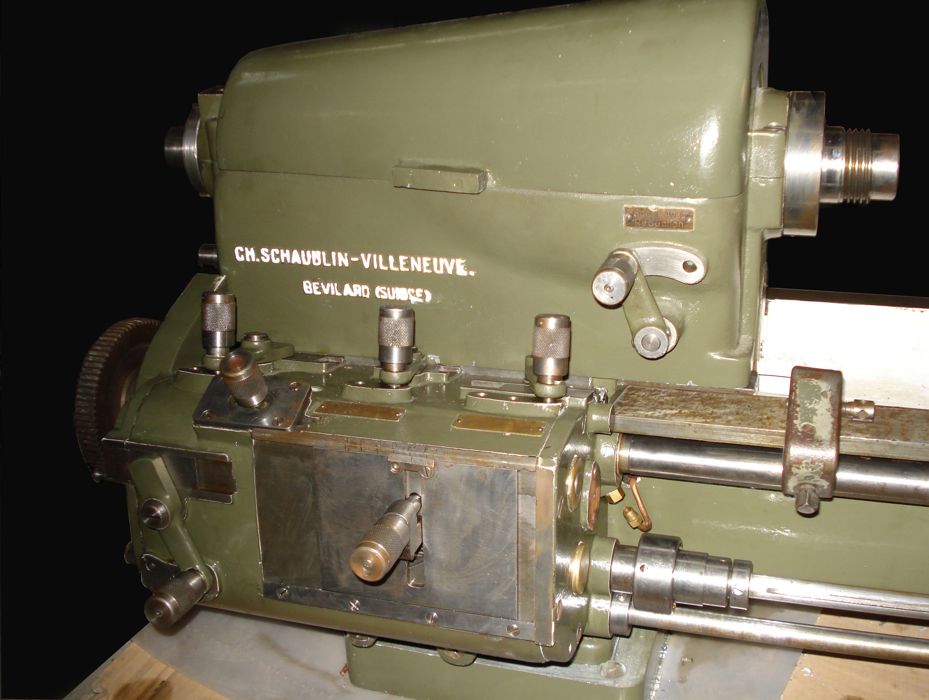
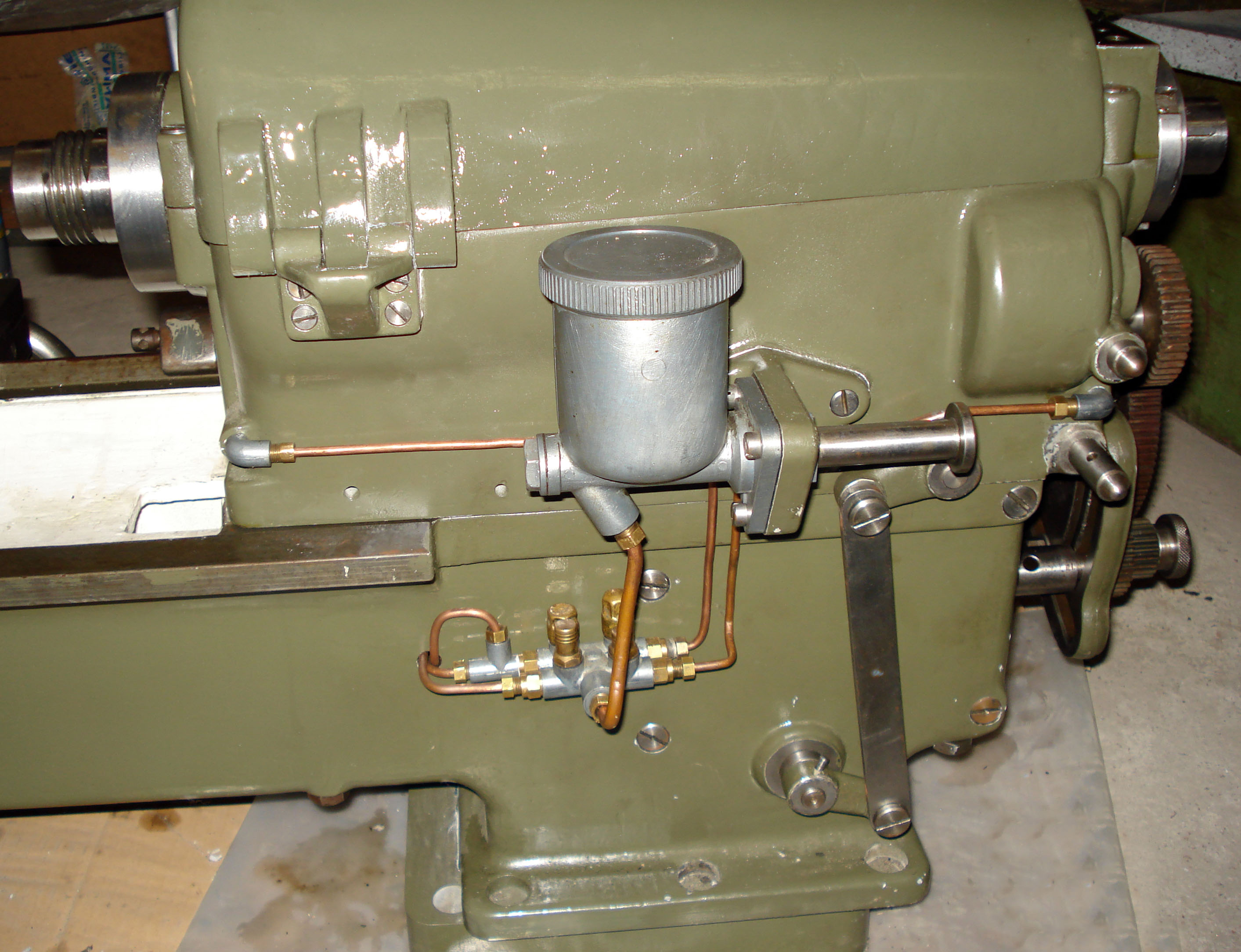
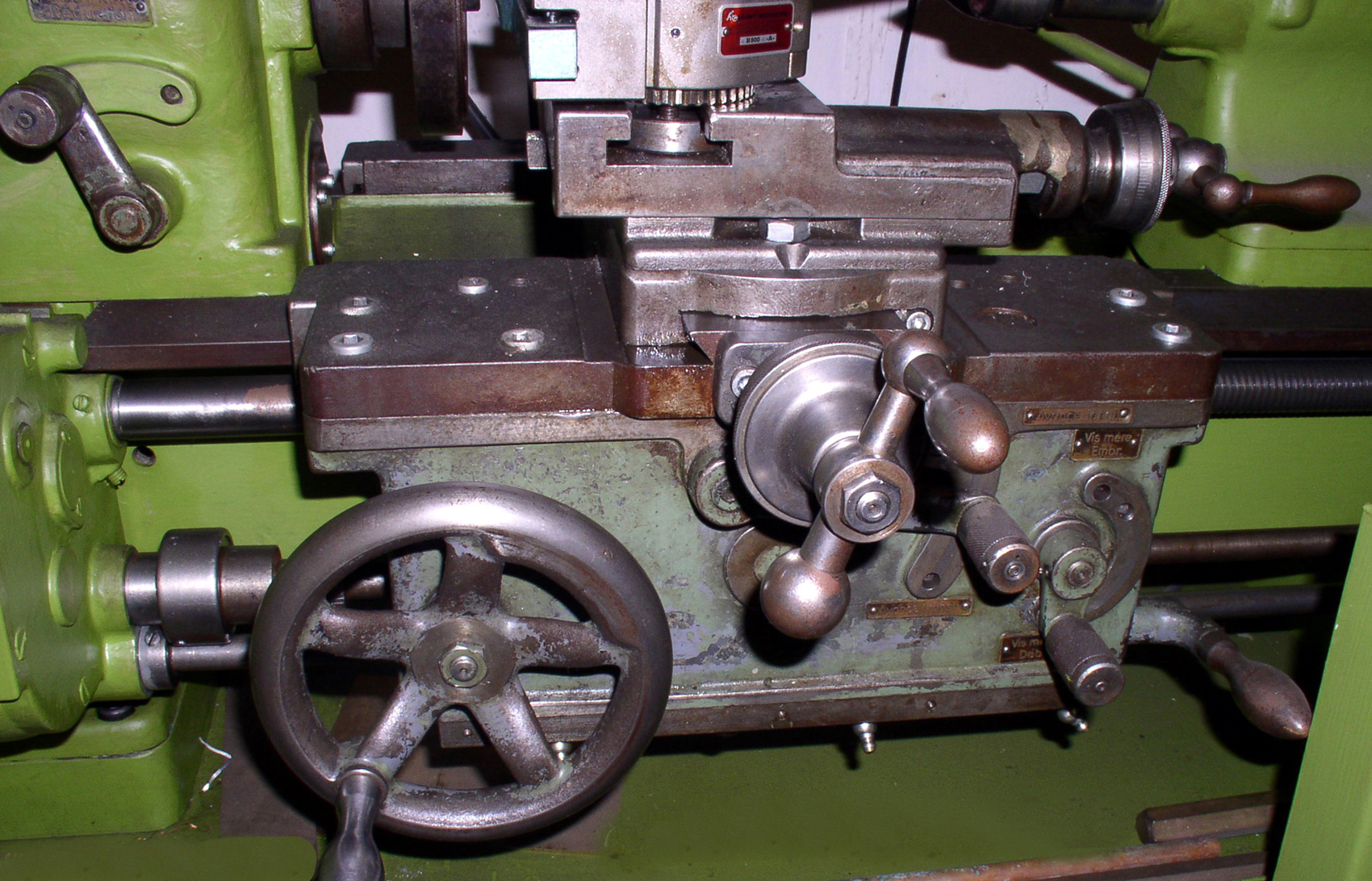
SV-130 Mk. 2: Screwcutting was by a complex, semi-sealed gearbox where, instead of the usual open slot across the front (and a row of exposed indentation holes) a steel plate was provided, running in guides top and bottom, that moved laterally with the lever. The quadrant lever to the left was also similarly fitted, a plate sealing the normally open hole where a stud connected to an internal selector. |
||
|
|
|
|
||
|
|
||
|
Home Machine Tool Archive Machine-tools Sale & Wanted |
||