 |
|
|
|
|
|
|
|
|
|
|
|
|
|
|
|
|
|
|
|
|
|
|
|
|
|
|
|
|
|
|
|
|
|
|
|
|
|
|
|
|
|
|
|
|
|
|
|
|
|
|
|
|
|
|
|
|
|
|
|
|
|
|
|
|
|
|
|
|
|
|
|
|
|
|
|
|
|
|
|
|
|
|
|
|
|
|
|
|
|
|
|
|
|
|
|
|
|
|
|
|
|
|
|
|
|
|
|
|
|
|
|
|
|
|
|
|
|
|
|
|
|
|
|
|
|
|
|
|
|
|
|
|
|
|
|
|
|
|
|
|
|
|
|
|
|
|
|
|
|
|
|
|
|
|
|
|
|
|
|
|
|
|
|
|
|
|
|
|
|
|
|
|
|
|
|
|
|
|
|
|
|
|
|
|
|
|
|
|
|
|
|
|
|
|
|
|
|
|
|
|
|
|
|
|
|
|
|
|
|
|
|
|
|
|
|
|
|
|
|
|
|
|
|
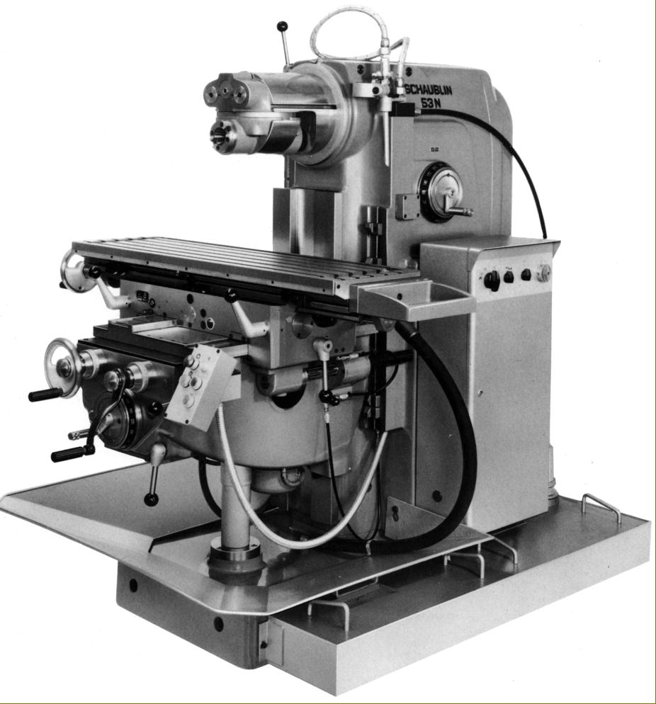
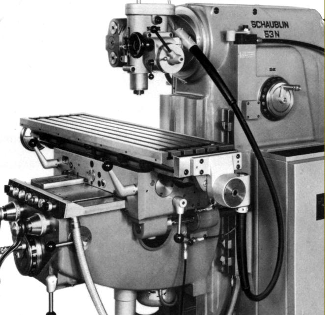
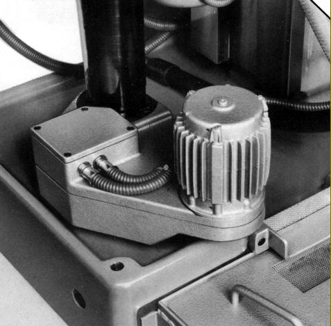
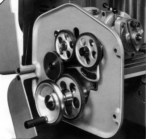
Last and best of the Schaublin Series 50 millers, the Type 53N was a development of the Type 53, a model produced for over 20 years. Advertised during the 1970s, the 53N preserved an identical layout to the previous versions but included a number of minor specification and one major design alteration - instead of being driven from an extension to the main spindle motor, table feeds were powered from a separate motor, the new system allowing an extra 0.6 kW of power to be retained for use by the milling spindle. Other alterations included redesigned main castings that weighed over 300 kg more to give improved stiffness, and a table increased in width by 50 mm (2") - so allowing the inclusion of a fifth T-slot and a corresponding increase in load bearing capacity. Vertical travel of the knee was increased by 60 mm, an alteration that also improved the maximum depth of a workpiece that could be held on the table. Now running in high precision preloaded angular-contact bearings, the spindle was better supported, retained its accuracy across a wider range of temperature range and had its brake controlled by a push button. Transmission gears, in a special grade of chrome-nickel steel with ground teeth, ran more quietly and the spiral-tooth bevel gears were made using the Klingeinberg system and then hardened and ground using a special process. All the gears and their associated hardware were made in the Schaublin factory at Orvin, a branch of the Company that specialised in that type of work. Electrical equipment was centralised in a separate cabinet that could be fastened to either side of the machine, or mounted remotely and the machine's push-button and switches centralised on a panel to the right of the knee. The milling head bearings were greased for life and lubrication of the knee, saddle and table assembly centralised and the use made, where possible of oil baths. Instead of the coolant equipment being built into the foot of the main column, the pump was driven by a 0.15 kW motor held in a 56 litre tank that bolted to the base, an arrangement that eased routine maintenance.
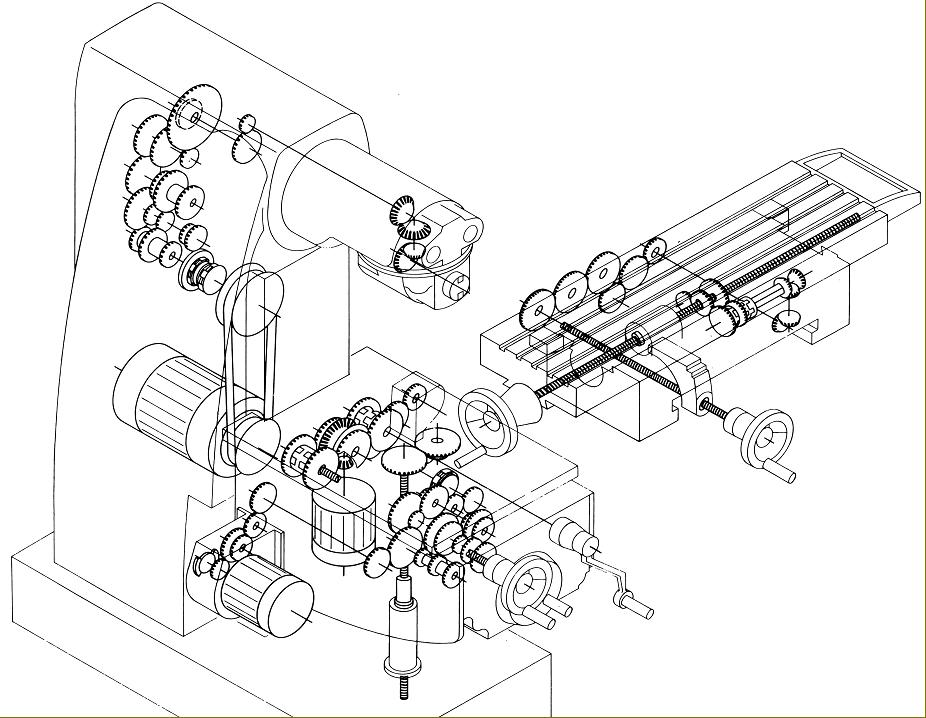
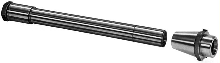
Heavily built - it weighed 2100 kg with standard equipment - the Type 53N was based on a patented design and used a massive (ventilated) main column and foot in cast iron to house the 3 kW 1500 r.p.m. spindle-drive motor and gearbox, the latter driven through an electromagnetic clutch and toothed transmission belt. While the column, drive system, knee and table were conventional enough, the head arrangement was, possibly, unique and gave the machine an ability to switch quickly between vertical and horizontal modes. Driven by bevel gears, the various heads were carried on the end of a sliding horizontal cylinder 240 mm in diameter that could be rotated through 360°, locked at 15° intervals and with an in-and-out travel of 300 mm. The spindle nose was an ISO 40 (the steep taper of which allowed the easy release of tooling) to specifications VSM 33931, size 44, or DIN 2079, size 40 with a positive, 2-key drive. The fitting was large enough to take a variety of useful adaptors down to 1, 2, 3 or 4 Morse and also carry (in suitable holders) Schaublin Type W20, W25 or E25 collets.
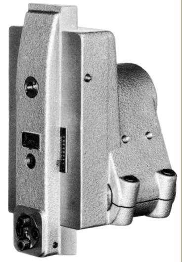
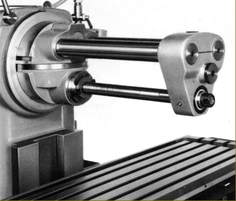
In order to set up for horizontal milling, instead of having to lift and mount a heavy overarm and drop bracket the operator simply pulled a pair of 50 mm diameter ram supports out from the face of the head with the cutter arbor (supplied in a number of lengths and diameters) being socketed into the horizontal spindle nose. While not as rigid as a more conventional system for most purposes it was, according to experienced users, perfectly adequate - especially if the optional bracing bar between bars and saddle were fitted together with an intermediate arbor support bracket.
Both standard and high-speed vertical heads were available, each driven from the main spindle. The former, with its fixed quill, had eighteen speeds of 38, 48, 60, 72, 92, 115, 140, 172, 212, 270, 340, 422, 515, 650, 800, 970, 1220 and 1510 r.p.m. and could be rotated on the end of the horizontal housing with an eccentric lock that gave precise clamping every 30 and 50° while also allowing any intermediate position to be set.
Continued below:
|
|
|
|
|
|
|
|
 |
|
|
|
|
|
|
Schaublin Type 53N as manufactured in the early 1970s
|
|
|
|
|
|
|
|
|
Continued:
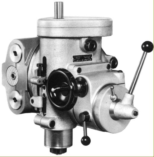
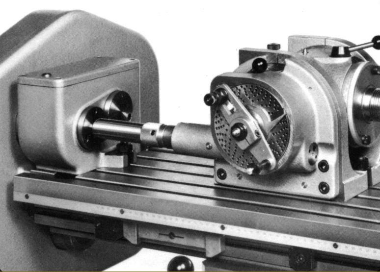
Designed to take Schaublin E25 collets, the 33 kg high-speed head had the same number of speeds as the standard version but spanning 150 to a usefully high 6000 r.p.m. An extra fitment on the high-speed head was a handwheel driven fine-feed and, as an option, an automatic power feed to the quill driven by a flexible cable from a worm-and-wheel gearbox clamped to the right-hand end of the table's feed screw.
Speeds, provided by a gearbox that had both oil-bath and spray lubrication (the latter provided by an immersed piston pump) were selected by a Cincinnati-type rotary control on the right-hand face of the column with every half-turn of the crank, in either direction, giving the next higher or lower rate with the dial automatically showing that selected. Lubrication of the horizontal cylinder and head was by pressure-fed mist, the benefits claimed including a cooling effect and an improved and more uniform distribution of the oil.
Fitted, rather inconveniently, with a (disengaging) handwheel at its left-hand side only, the 1100 x 305 mm (43.25" x 12") table had five T-slots on 50 mm (2") spacing and 700 mm of longitudinal travel, 250 mm across and 490 mm vertically - the figures remaining unaltered when used under power. A gearbox, driven by a separate motor housed within the knee, provided the eighteen rates of feed that ranged from
10 to 1050 mm (0.47" to 41.3")/min longitudinally and in traverse and from 6 to 525 mm (0.23" to 20.6")/min vertically. The feeds were protected by an overload clutch that was non-adjustable and alerted the operator to its engagement by rattling noise. Rapids (on all axes) were powered by a separate 1.2 h.p. 3,000 r.p.m. motor and, rather usefully, the spring-loaded push button on the knee that engaged them (it had to be held down of course to keep the drive engaged) could also be used as an inching control. Rapid rates were set at 3500 mm (138")/min in both horizontal planes and at a more sensible and safe 1750 mm (69")/min vertically. Rates of power feed were selected by a single dial on the front of the knee, its action duplicating that of the spindle-speed control with each half-turn in either direction producing the next higher or lower rate. Levers were used to engage the feeds, each causing the drive to travel in the direction of their movement and with those for the horizontal movement duplicated at each end of the saddle and linked together.
Working on both the ordinary and rapid feeds, fixed over-run and adjustable auto-disengage stops were fitted to each feed axis and, in addition to (reasonably large) micrometer dials fitted with zeroing verniers, each feed was also equipped with a finely inscribed ruler with, on the vertical motion, a magnifying glass to help achieve an accurate setting. The nut though which the longitudinal feed screw ran could be adjusted to remove play, though this involved some dismantling, but in the case of the cross-feed any slackness between nut and screw could only be corrected by machining both a cover plate and a sleeve assembly - not something that the average user would be inclined to attempt.
Arrangements for lubrication were comprehensive with the feed gearbox in the knee oiled by a submerged piston-type oil pump, the saddle parts and longitudinal feed screw by an oil bath and the table and saddle slides and cross-feed feed screw by a hand-operated piston pump that drew oil from a reservoir. Oil for the highly stressed knee-lift screw was by a constantly circulating supply of oil drawn from a tank formed as an integral part of the casting that surrounded it, a similar system being employed for many years on Cincinnati millers.
In addition to the expected cutter holders, centre and cutter adapters, boring heads, swivelling and static-base machine vices and rotary tables and dividing heads, a number of useful accessories were available including an automatic cycle system programmed by dogs held in T-slots on the front of the table; a powered device for the automatic disengagement of the table's vertical position (for use only with the automatic cycle equipment); a slotting head with its stroke adjustable from 0 to 7 mm (0 to 3.75") and stroke from 17 to 500 per minute; a rotary table power-feed attachment driven from the end of the table feed screw; a copy-milling attachment (used in conjunction with the powered rotary table); a centring microscope with built-in lighting; precision length-bar holders for each axis that also accepted dial-test indicators and other contemporary precision measuring systems including optical readers..
|
|
|
|
|
|
|
 |
|
|
|
|
|
|
|
|
|
 |
|
|
 |
|
|
|
|
|
|
|
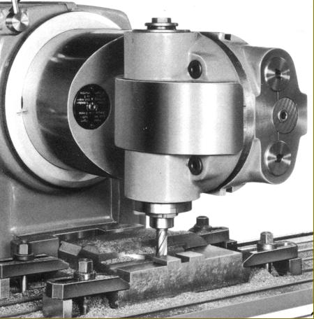
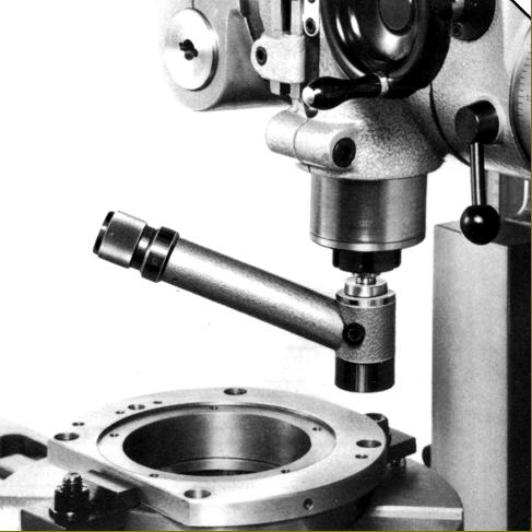
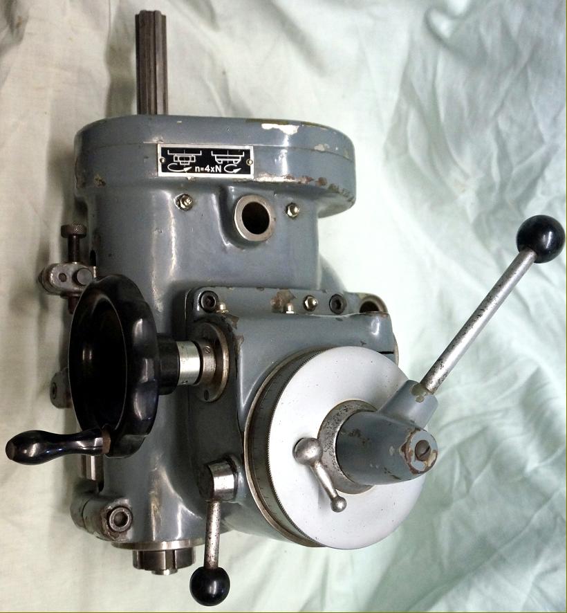
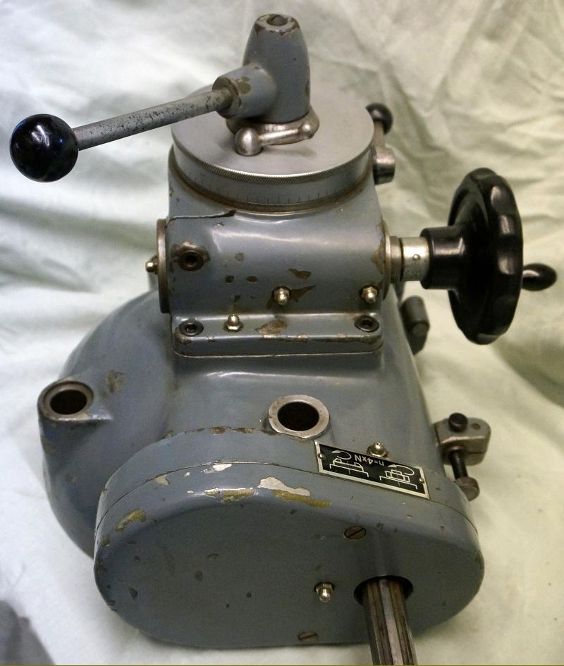
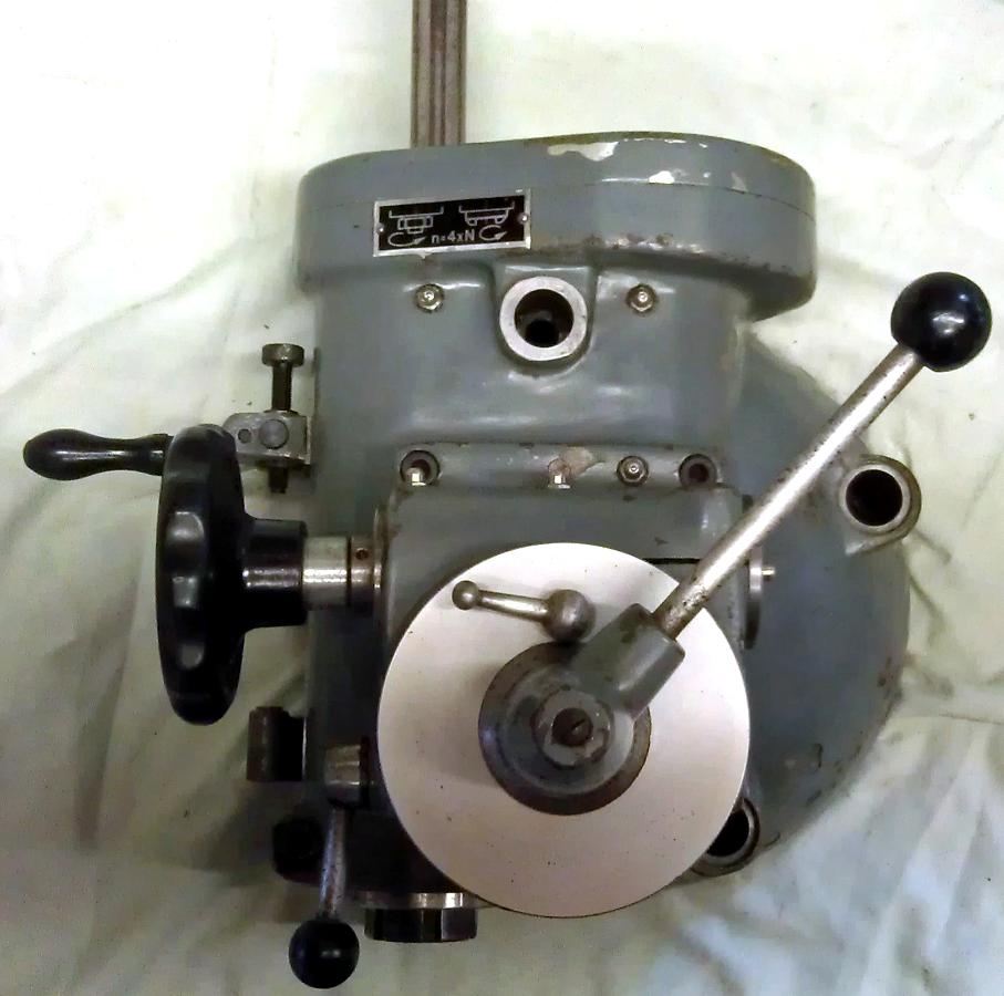
53-11.100 Universal high-speed drilling, milling and boring head with both fine and quick-action drilling feeds - this unit provided speed 4 times faster than the standard head making it ideal for drilling and the use of small-diameter milling cutters. An additional part, Accessory 53-11.30,0 provided a drive, via a flexible cable, from the end of the table feed screw
|
|
|
|
|
|
|
|
|
|
Slotting Attachment: stroke 0 to 70 mm with rates variable from 17 to 500/minute
|
|
|
|
|
|
|
|
|
|
|
 |
|
|
|
|
|
|
Accessory 53-11.300 provided a drive, via a flexible cable, from the end of the table feed screw to the Universal high-speed head
|
|
|
|
|
|
|
|
 |
|
|
 |
|
|
|
|
|
|
|
|
|
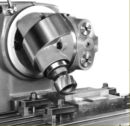
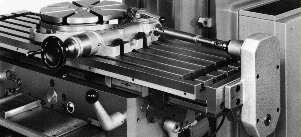
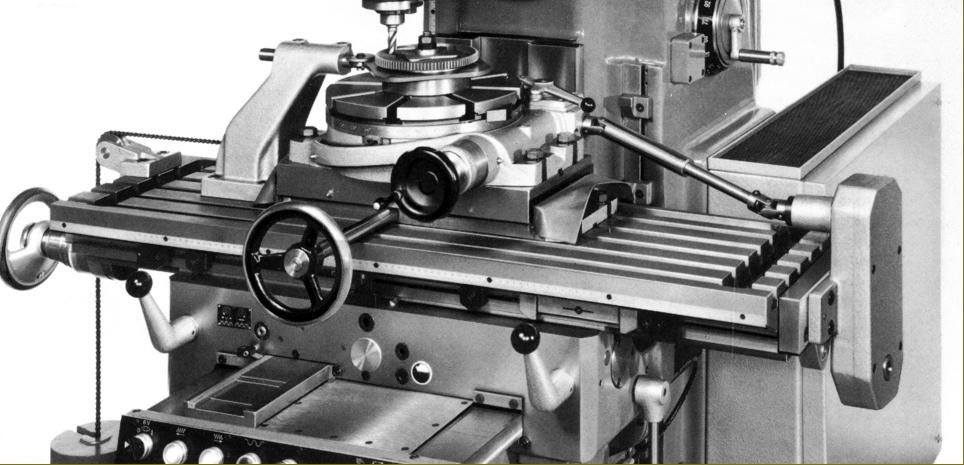
Horizontal milling attachment - part of the standard equipment
|
|
|
|
|
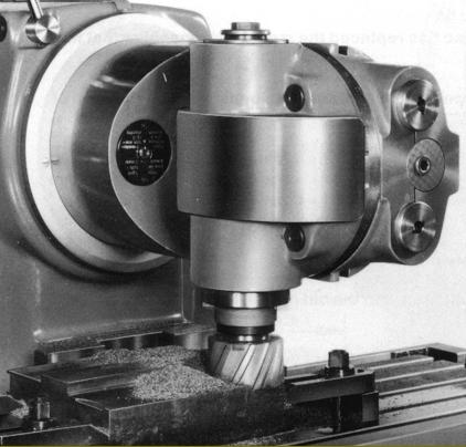
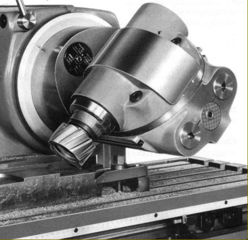
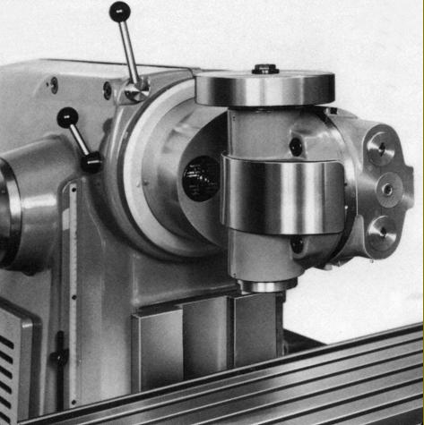
Universal vertical head. Especially rigid the unit could be swivelled on two axes and indexed precisely at pre-set intervals
|
|
|
|
|
|
|
|
|
|
|
 |
|
|
 |
|
|
|
|
|
 |
|
 |
|
|
|
|
 |
|
|
|
 |
|
|
|
|
|
|
 |
|
 |
|
|
|
|
|
|
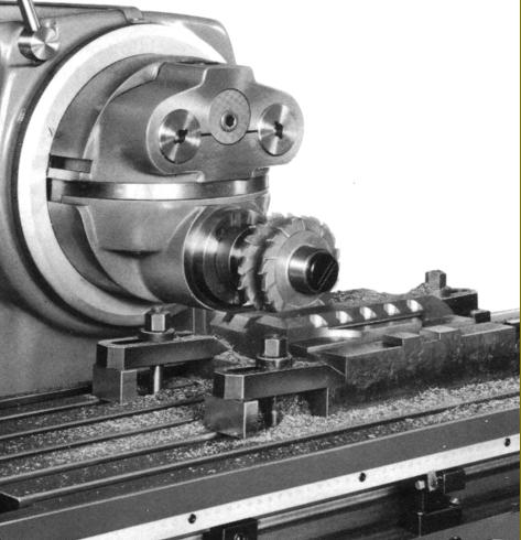
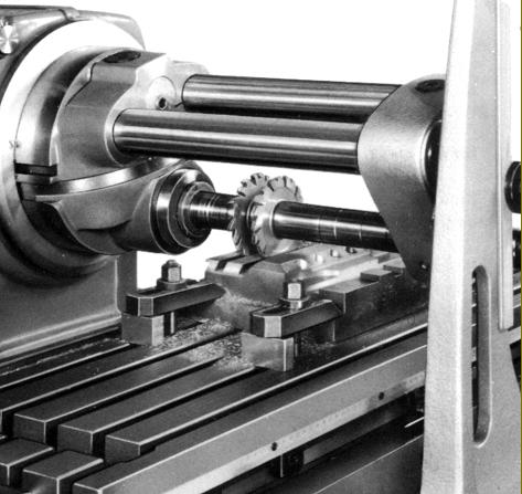
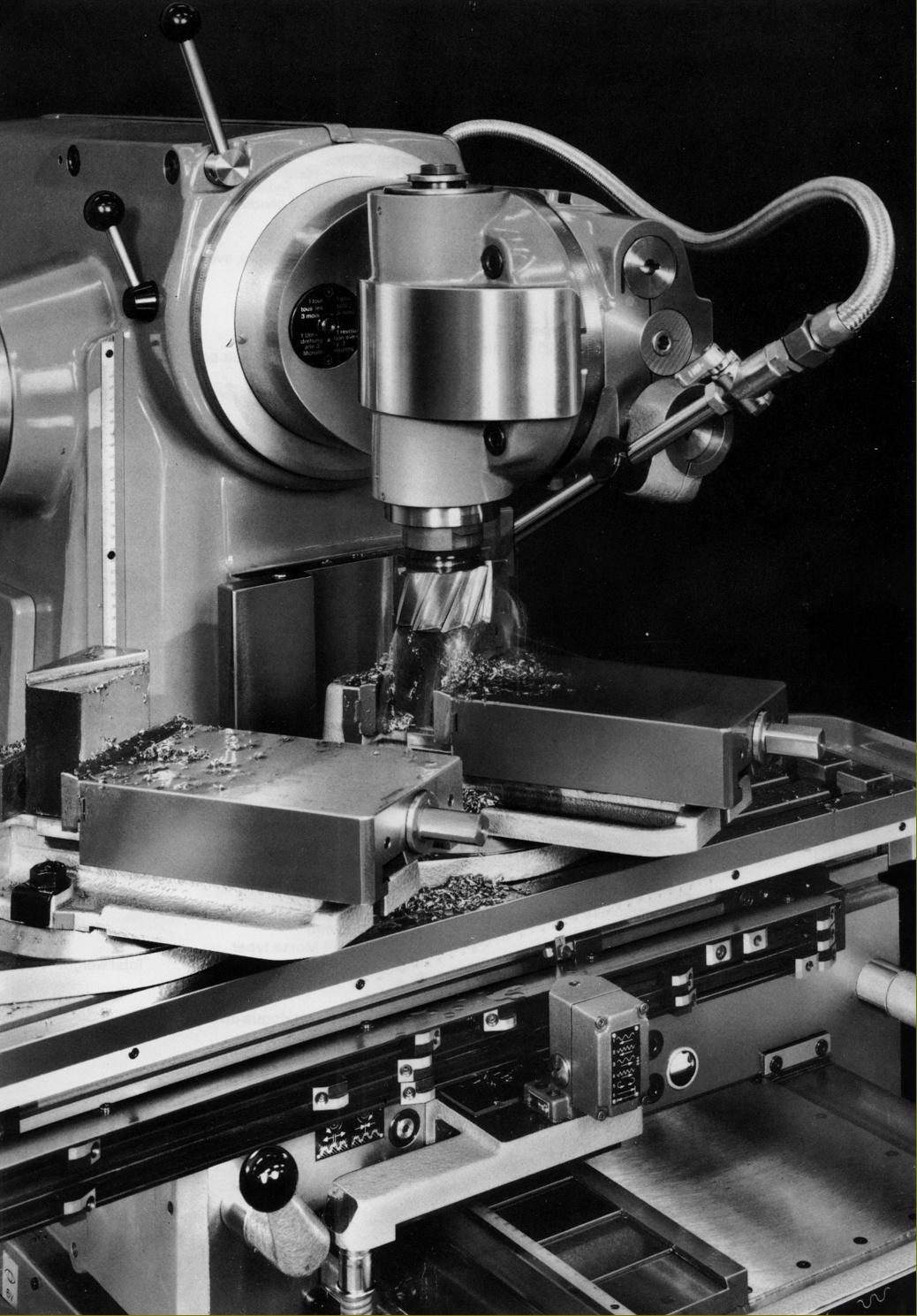
Two side and face cutters mounted on the horizontal arbor
|
|
|
|
|
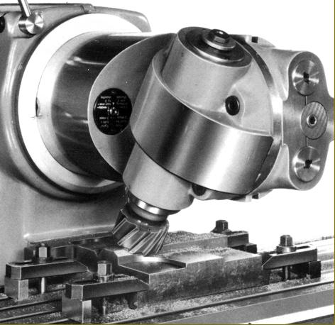
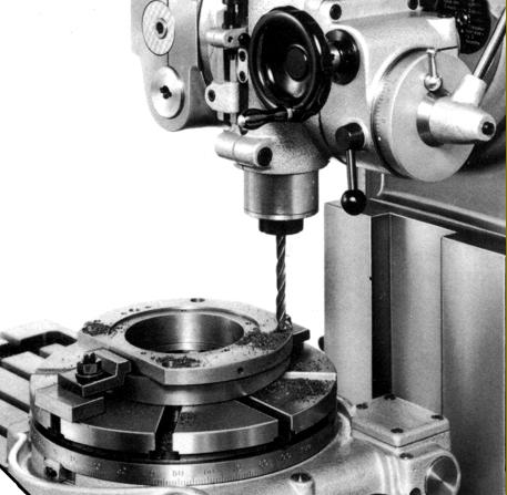
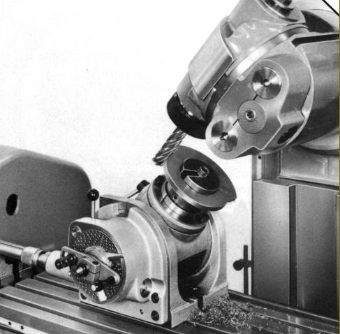
Drilling holes using a Schaublin rotary table and high-speed head
|
|
|
|
|
|
|
|
|
|
 |
|
|
|
 |
|
|
|
|
|
|
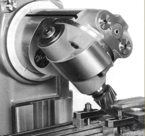
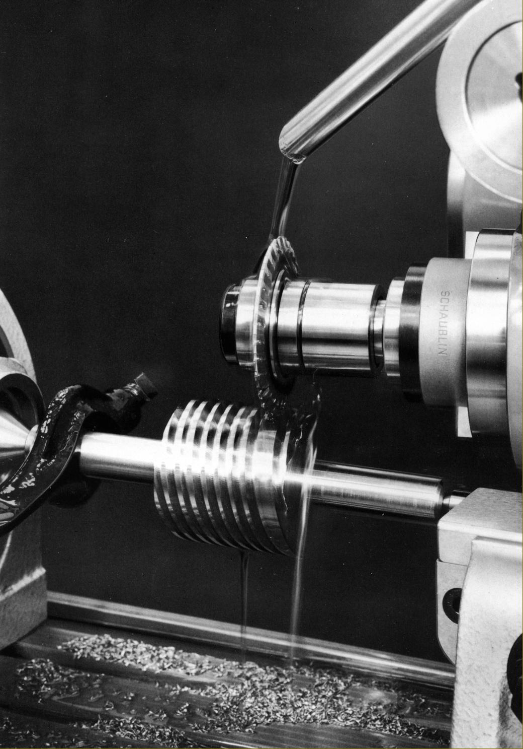
Form milling: a cam for a Swiss-type automatic lathe
|
|
|
|
|
|
|
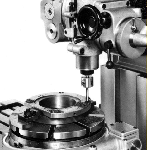
Precision boring head in use on the high-speed head
|
|
|
|
|
|
|
|
|
|
|
 |
|
 |
|
|
|
|
|
|
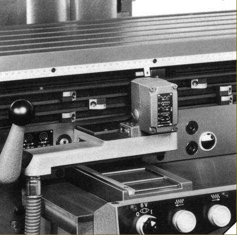
Accessory 53-6.750 Automatic cycle control for longitudinal feed
|
|
|
|
|
|
|
|
Accessory 53-6.760 a device to give automatic vertical disengagement of the table - only for use in conjunction with the automatic cycle control and not manually
|
|
|
|
|
|
|
|
|
|
 |
|
|
|
 |
|
|
|
|
|
|
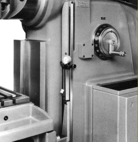
Accessory 52-1.143 Holder for dial indicator to fit into the bore of the quill travel stop
|
|
|
|
|
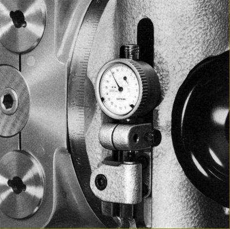
Accessory 53-6.690 holder for dial indicator and slip gauges
|
|
|
|
|
|
|
|
|
|
 |
|
|
|
|
|
|
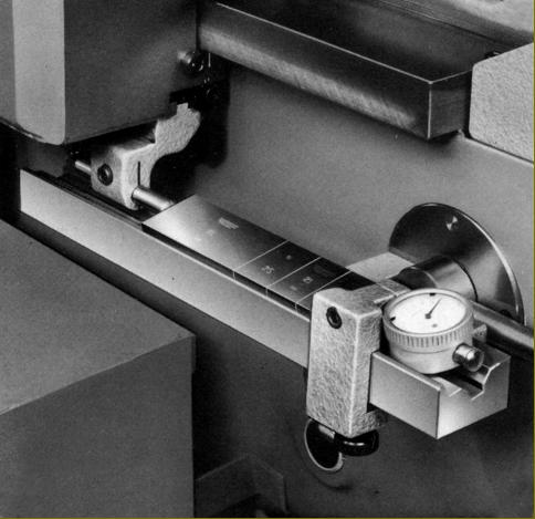
Accessory 53-6.695 Dial indicator and slip-gauge holder for longitudinal measurements and 53-11.841/11.842 dial indicators reading to 0.01 mm and 0.002 mm respectively
|
|
|
|
|
|
|
 |
|
 |
|
|
|
|
|
|
|
|
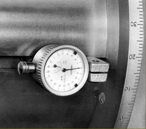
Accessory 53-6.675 Dial indicator holder for measuring axial movement of the milling head and Accessories 53-11.841/11.842 dial indicators reading to 0.01 mm and 0.002 mm respectively
|
|
|
|
|
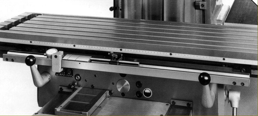
Accessories 53-6.540 53-6.545 Optical reading equipment for. Respectively, longitudinal and transverse travels
|
|
|
|
|
|
|
|
|
|
 |
|
|
|
 |
|
|
|
|
|
|
Accessory 53-6.685 Dial indicator holder for measuring vertical movements and Accessories 53-11.841/11.842 dial indicators reading to 0.01 mm and 0.002 mm respectively
|
|
|
|
|
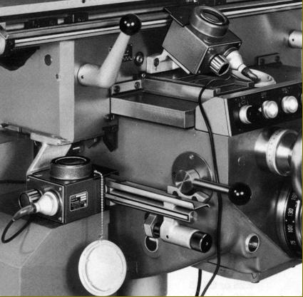
Accessory 53-11.112 Centring microscope with built-in lighting and a stem diameter of 12 mm. Magnification 20X
|
|
|
|
|
|
|
|
|
|
 |
|
 |
|
|
|
|
|
|
Accessories Flywheel 53-6.101 and special drawbar 56-6.103 for use when milling with a cutter adapter. Mass flywheels aimed to reduce vibration by increasing the inertia of the spindle. Five different weights were available from 11.5 to 15.7 kg.
|
|
|
|
|
|
|
|
Flywheels could also be mounted on the end of the horizontal milling arbor
|
|
|
|
|
|
|
|
|
|
 |
|
|
|
 |
|
|
|
|
|
|
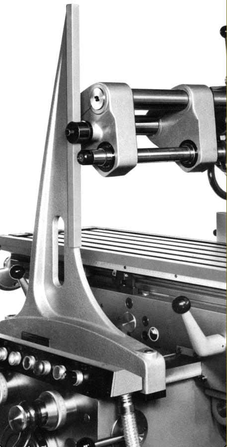
Accessory 53-6.110 Overarm brace - clamped to knee by two bolts
|
|
|
|
|
Accessories 53-6.050, 53-6.052, 53-6.058, 53-6.089 and 53-6.090: All intermediate arbor supports to stiffen the assembly part way along the shafts
|
|
|
|
|
|
|
|
|
|
 |
|
|
|
|
|
|
Accessory 53-10.550 Attachment to drive, using a universally-joined shaft, the rotary table from the end of the table feed screw. Knock-off dogs were provided to limit the angular movement
|
|
|
|
|
|
|
 |
|
|
|
|
|
|
Accessory 53-6.800C Copy milling attachment for use in conjunction with the rotary table fitted for drive by the Universal shaft Type 53-10.550
|
|
|
|
|
|
|
 |
|
 |
|
|
|
|
|
|
|
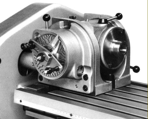
Accessory 53-9.000 Inclinable universal dividing head
|
|
|
|
|
|
|
|
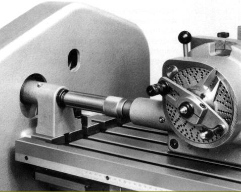
Accessory 53-9.110 Extension shaft to drive the dividing head when mounted towards he middle of the table
|
|
|
|
|
|
|
|
|
|
 |
|
|
|
|
Accessory 53-9.200 10 : 1 speed multiplier for milling of helixes with sort leads between 3.7 and 500 mm.
|
|
|
|
|
|
|
 |
|
 |
|
|
|
|
|
|
|
|
Accessory 53-9.100 Quadrant with changewheels for use in conjunction with the table power feed and the Universal dividing head 53-9.000
|
|
|
|
|
Accessory 53-9.120 Indexing attachment for milling multi-start threads; the mounting was direct on the spindle of the Universal head
|
|
|
|
|
|
|
|
|
|
|
|
|
 |
|
|
|
|
|
|
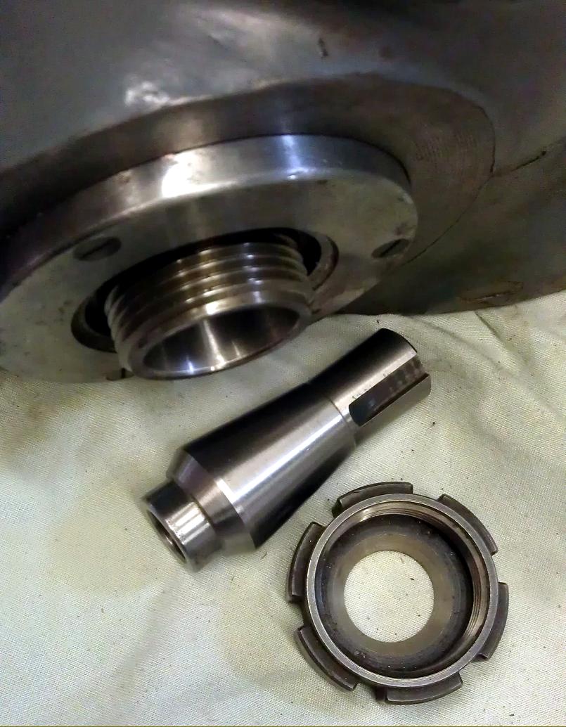
Left: Accessory 53-6.171 Drawbar to hold (right) spindle reduction sleeve 53-6.746
|
|
|
|
|
|
|
 |
|
|
|
|
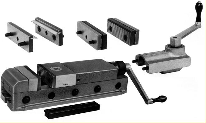
Accessory 53-13.150 High-pressure production vice with accessories. Jaws 125 mm wide, opening capacity 170 mm
|
|
|
|
|
|
|
 |
|
|
|
|
|
|
|
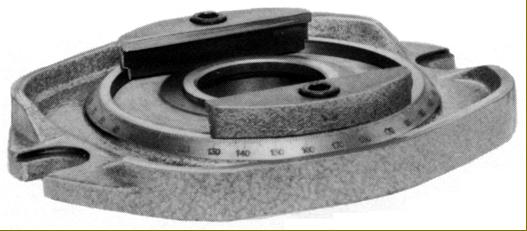
Accessory 53-13.155 Swivel base for vice 53-13.155
|
|
|
|
|
|
|
|
|
|
|
 |
|
|
|
|
|
|
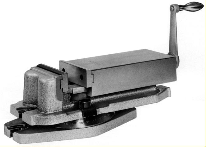
Accessory 53-13.000 Precision swivel-base parallel-jaw vice. Jaw width 140 mm maximum jaw opening 102 mm
|
|
|
|
|
|
|
 |
|
|
|
|
 |
|
|
|
 |
|
|
|
|
|
|
|
|
|
53-11.100 Universal high-speed drilling, milling and boring head with both fine and quick-action drilling feeds - this unit provided speed 4 times faster than the standard head making it ideal for drilling and the use of small-diameter milling cutters. An additional part, Accessory 53-11.30,0 provided a drive, via a flexible cable, from the end of the table feed screw
|
|
|
|
|
|
|
|
|
 |
|
|
|
|
 |
|
|
|
|
 |
|
|
|
|
|
|
|
|
|
|
|
|
|