|
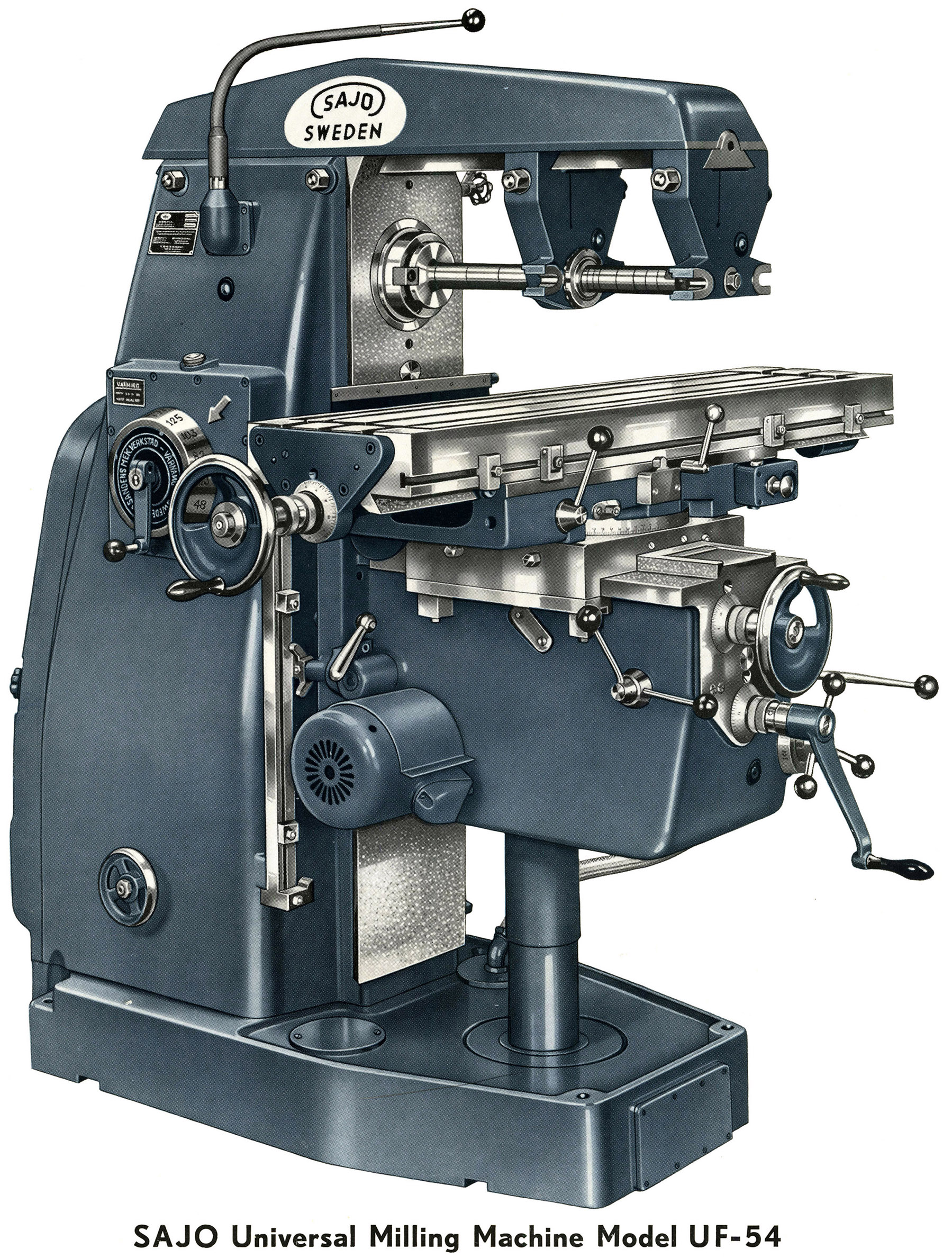
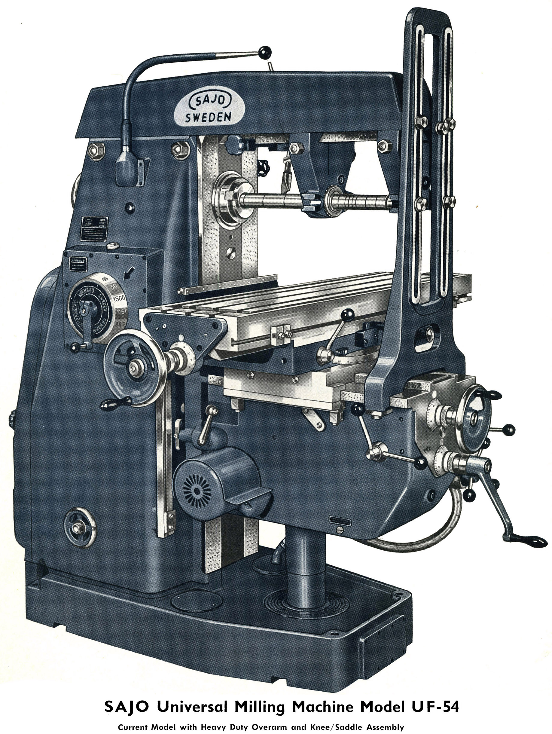
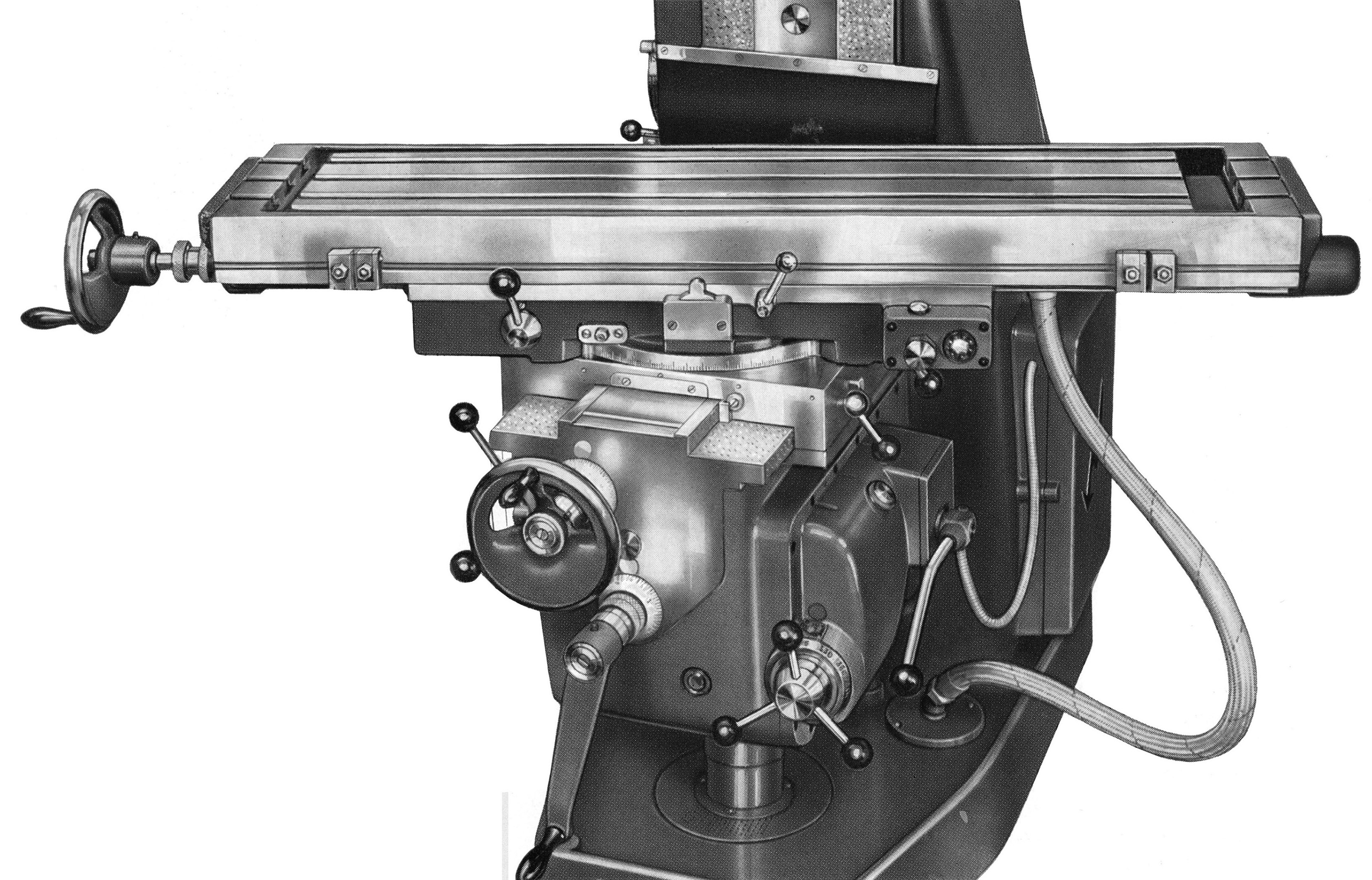
Sold during the 1950s and 1960s, the Model 54 was built in Mk. 1 and Mk. 2 versions and as the Type PF54 Plain Horizontal , Type UF54 Universal with swivelling table , the Duo Mill 54 with a self-powered "Toolmakers" overarm, the Type 54 Vertical with and without power down feed to the quill (also offered with automatic table cycling) and the production millers Types APF Plain and AVF54. Easily identified, the Mk. 1 had a dovetail-fitting overarm triangular in side elevation section with a much greater depth in the centre - while on the Mk. 2 this difference was greatly reduced and the arm flatter. On the Mk. 1 the knee had a shallow return angle to the lower front face of its, this being noticeably increased on the Mk. 2
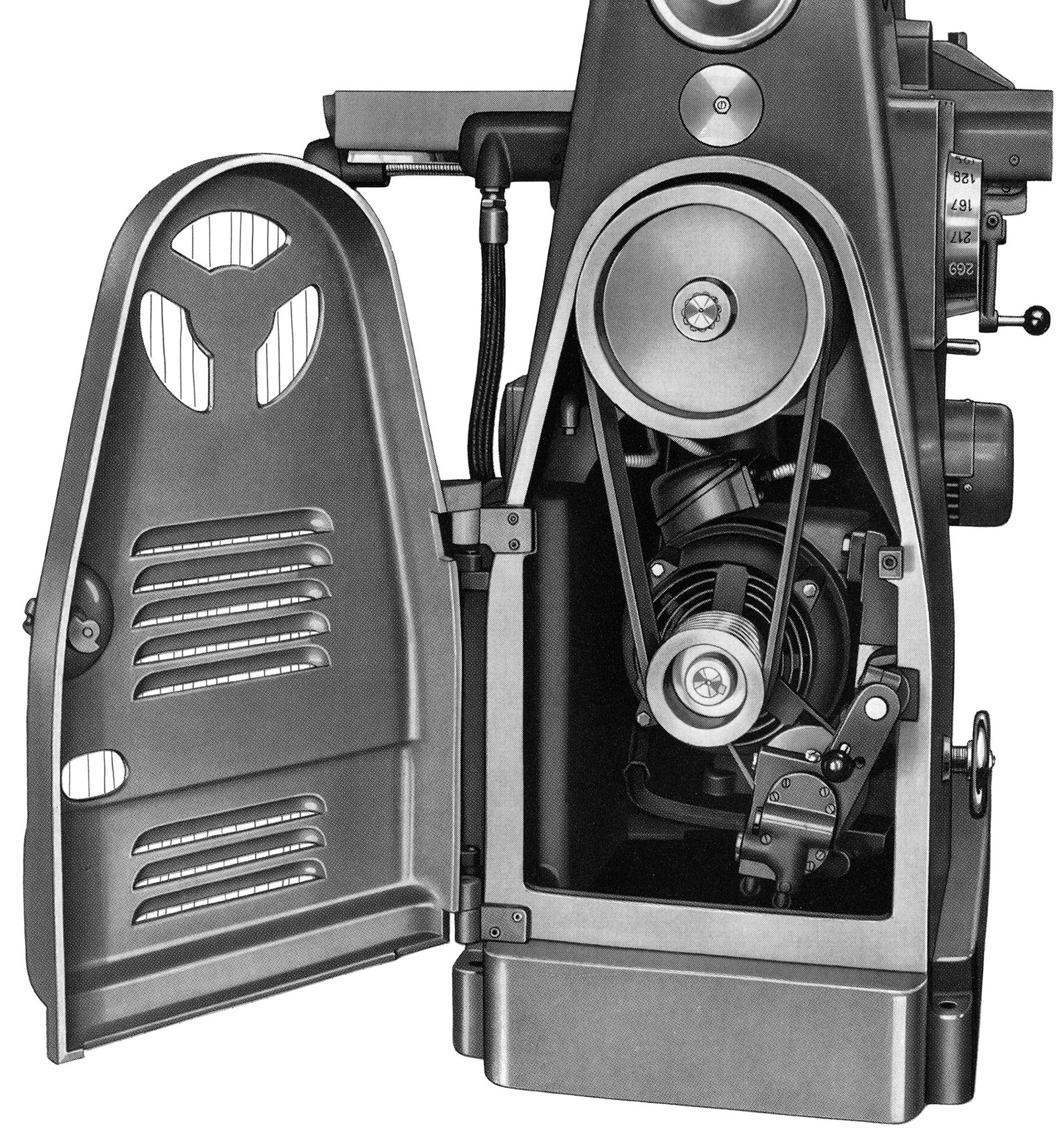
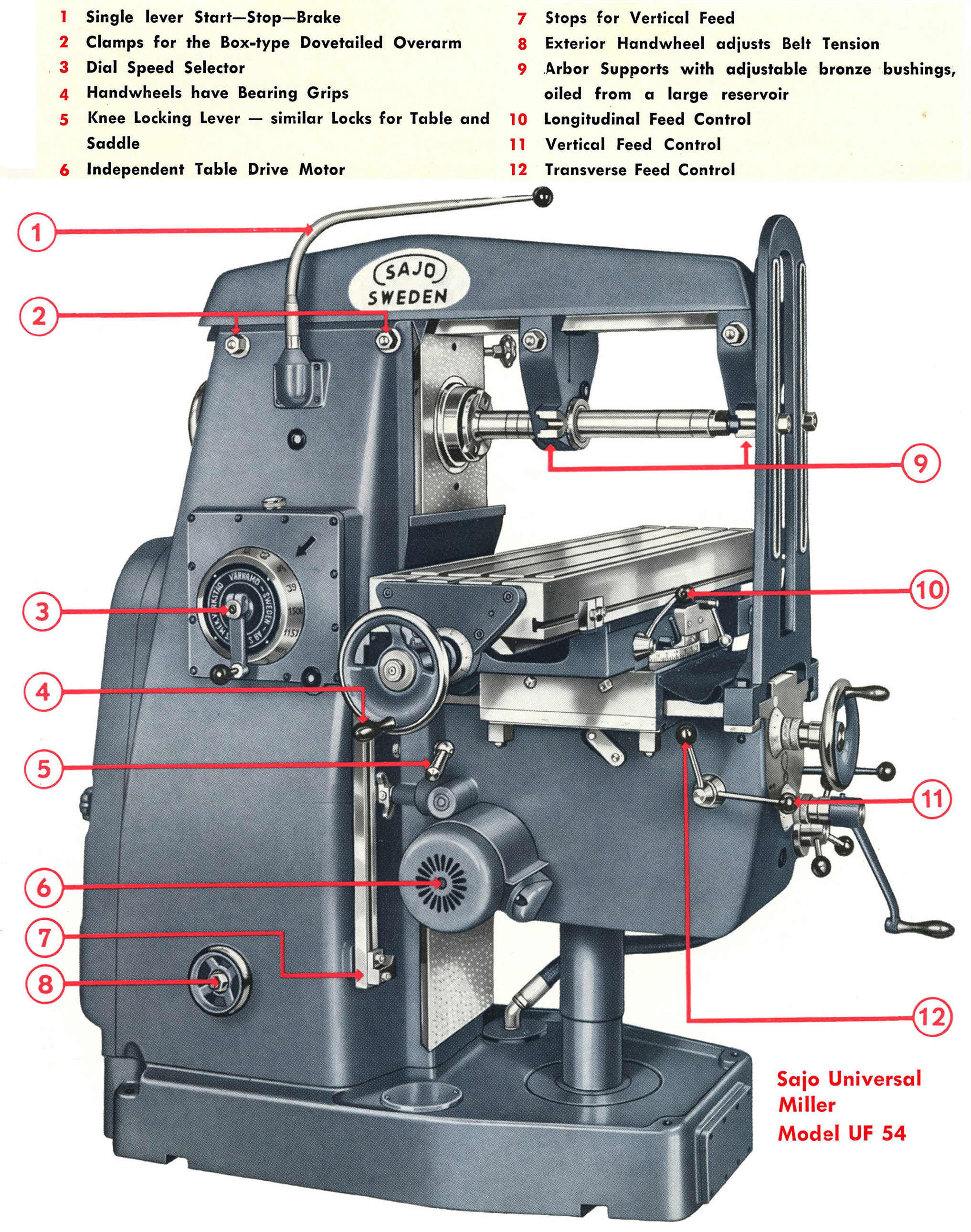
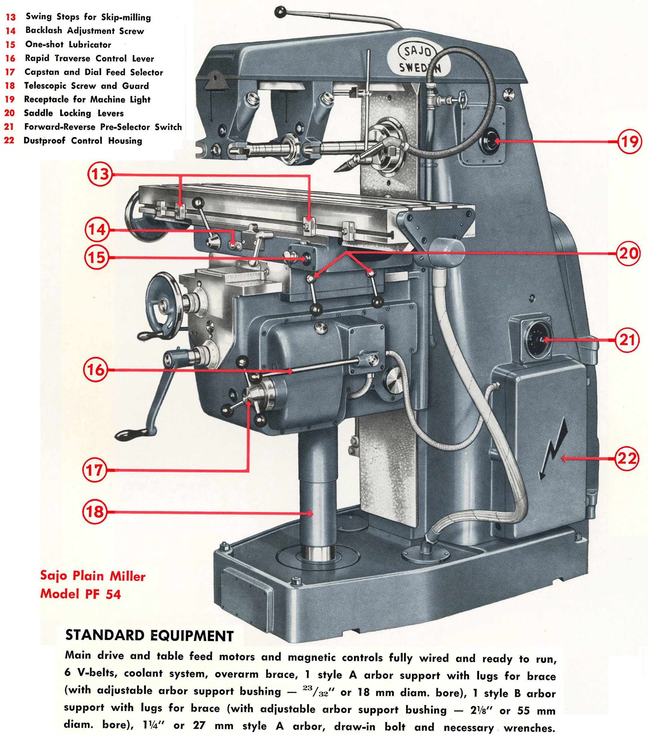
Both versions of the Model 54 were built around a substantial column casting formed as one piece with a heavy foot that doubled as a coolant tank. Inside the foot, ribbing increased its rigidity and was utilised as swarf settling traps. A door on the right-hand side of the column gave access to the electrical system (with a plug provided for an extra-cost light unit) with, at the back of the column, a hinged door to cover the 6 h.p.motor (7 or optionally 5 h.p. on the Mk.2) - both driving, using six V-belts, direct to the spindle speed-change gearbox. With the motor mounted on an adjustable plate, to adjust the belt tension, an external handwheel was provided at the bottom of the column's left-hand face.
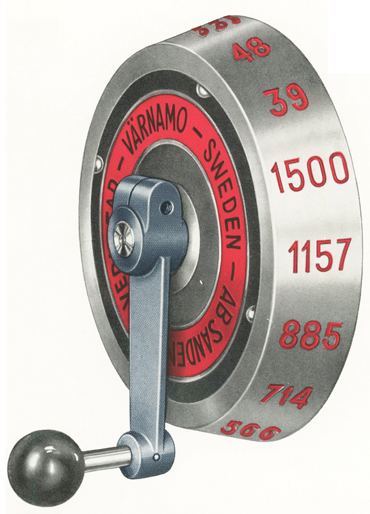
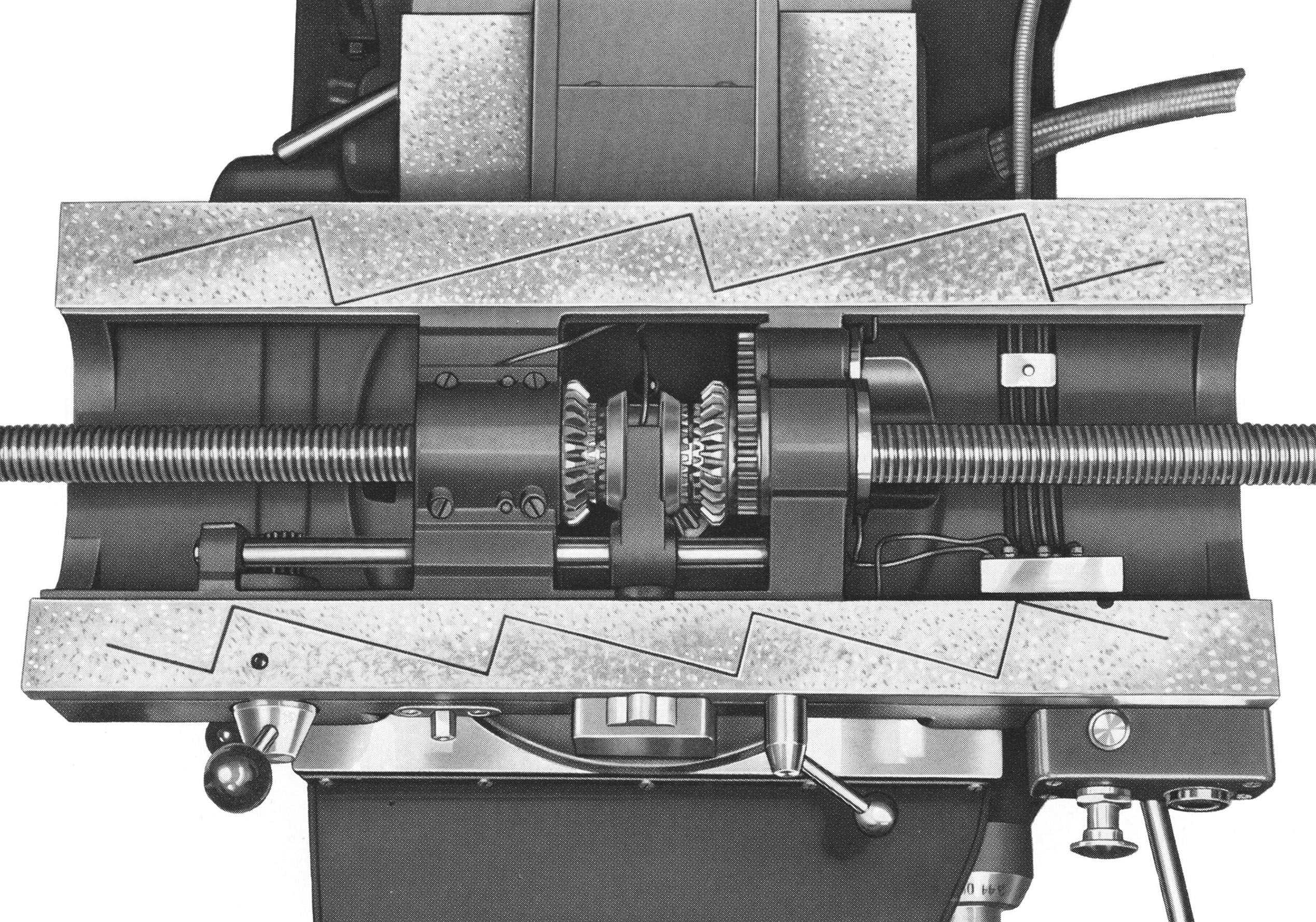
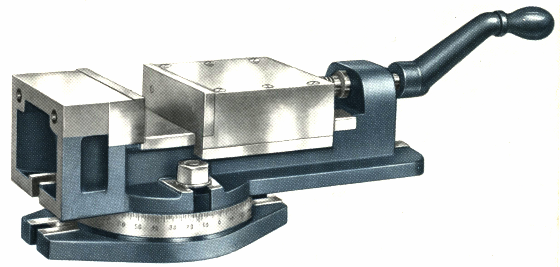
The Sajo 54 was offered in both Plain Horizontal and "Universal" types, the latter having a table that could be swing on its vertical axis by up to 45° on each side of central. Following the example of Cincinnati mailers dating from the late 1930s, control of spindle speeds was by a large dial set on the left-hand face of the column; one movement of the crank handle fitted to the dial selected the next higher or lower spindle speed - of which sixteen reversible ones were available that spanned either 39 to 1500 r.p.m. or, optionally, 31 to 1200 r.p.m. Electrical control of the miller's spindle drive was by a triple-function lever - mounted on the left of the column and adjustable for position - that gave a start, stop and brake function, the latter by applying gentle pressure in the stop position.
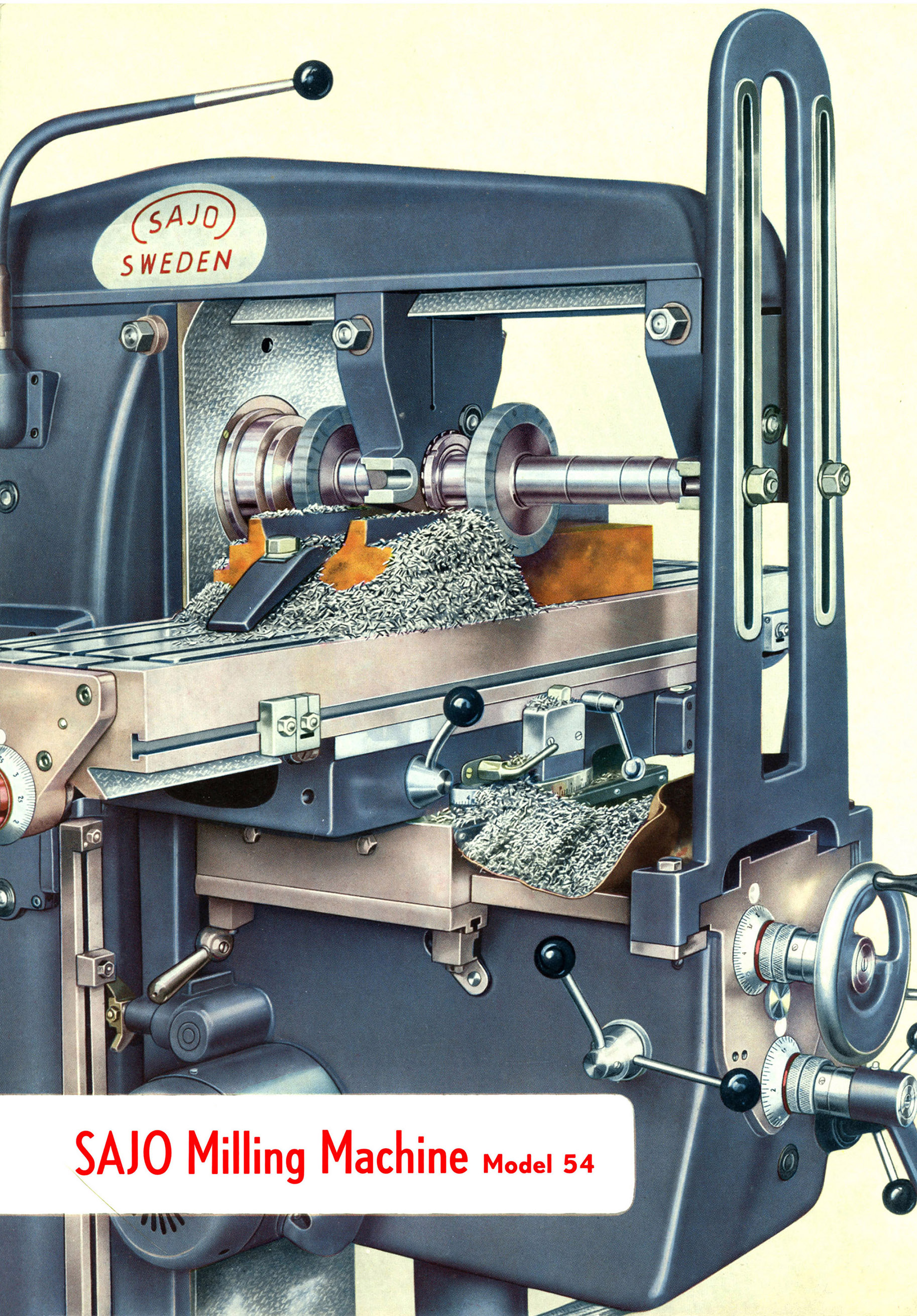
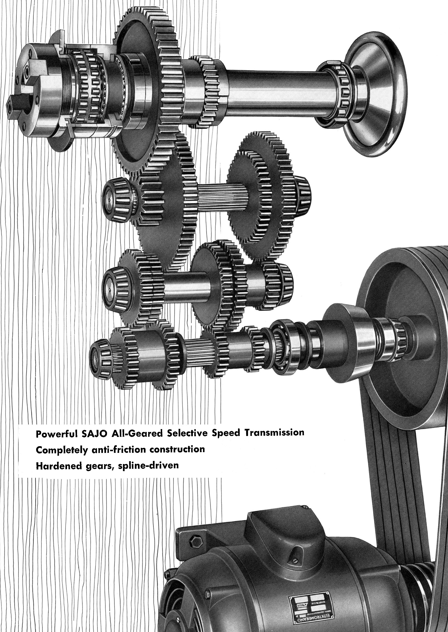
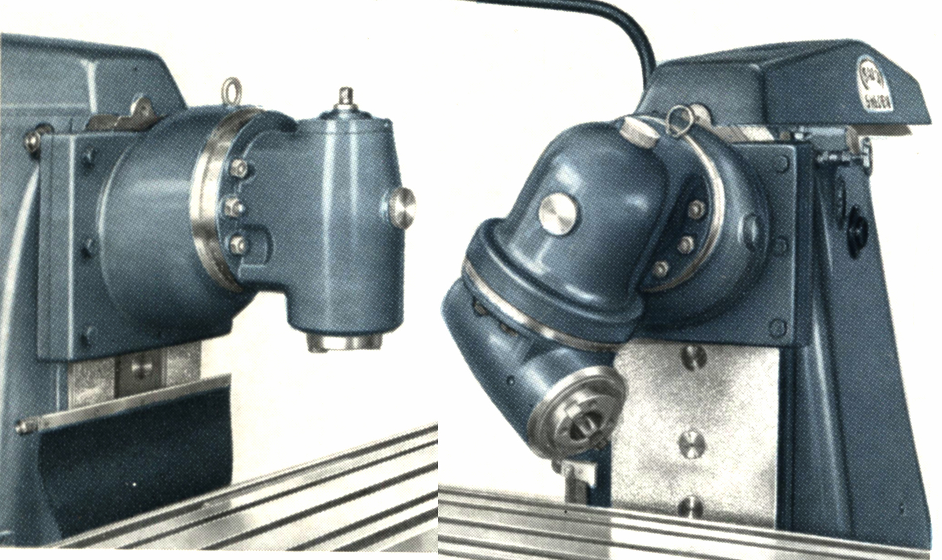
Fitted with a No. 50 INT nose that was hardened inside and out and machined from a chrome-nickel steel forging, the spindle ran, of course, in a high-class grade of Swedish-made SKF bearings. At the nose, a staggered, double-row cylindrical roller took radial loads, two ball thrust bearings immediately behind absorbed axial thrust and, supporting it at the other end, was a single cylindrical bearing Fitted with provision for adjustment, the bearings were all of the "SP" -special precision - type. Inside the main column, the speed-change gears were all in the very best grade of "Bofors" alloy steels and hardened and ground (or shaved) for their particular function. All the gear-carrying shafts ran in SKF anti-friction bearings with lubrication a pressure pump.
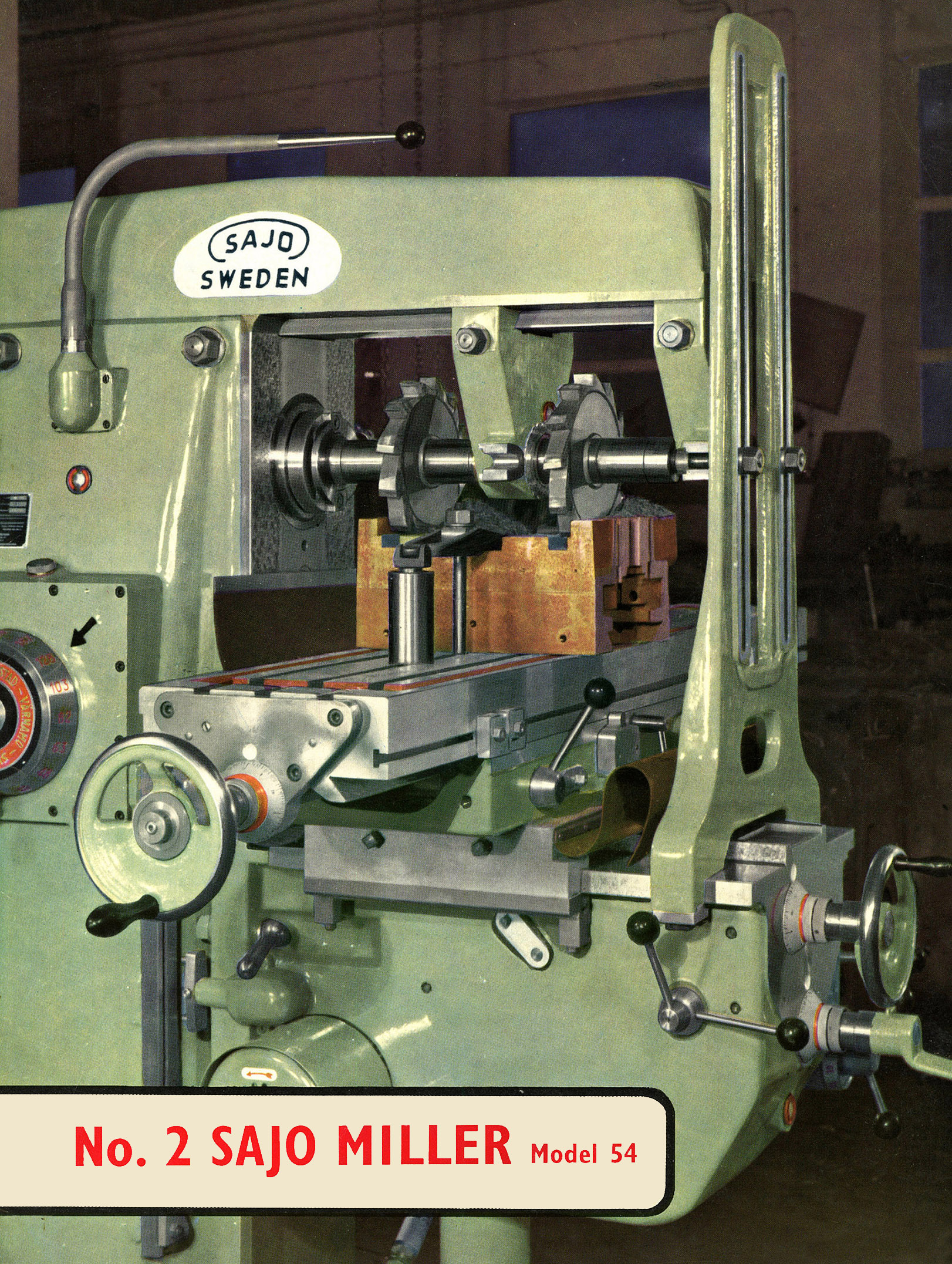
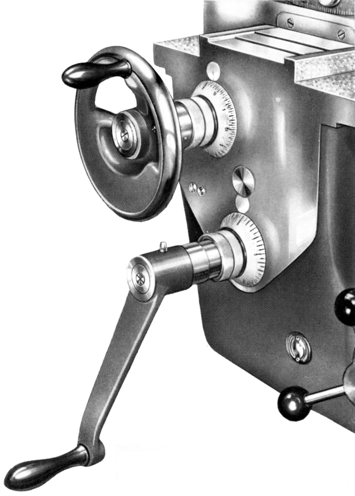
One inch (25 mm) in diameter, the cutter-holding arbor was a precision ground forging of nickel-chrome steel and carried a set of lapped spacers; it was supported at its outer end in a single drop arm fitted with an adjustable bronze bush that was oiled from wicks dipping into a reservoir held within the overarm. Of the dovetail type, the overarm was cored from one end only to provide an unbroken and hence twist-resistant tubular section; its slides were precision ground to fit into the hand-scraped slides on top of the main column turret.
|
|