|
A mainstay of the pre-WW2 Czechoslovakian industrial scene was Volman Machine Tools, a company founded in 1910 by Joseph Volman in a country town, Celákovice, 16 miles east of Prague in what is now the Czech Republic. Still in existence today as "TOS-MET spol.sr.o" the company's first products were humble drills, knives and manual presses - items similar to those already made by Volman's brother Frantisek, since 1872, in a factory at Žebrákx; it was not until 1925 that the newer Volman enterprise had sufficient expertise to become the first CZ manufacture of centre (engine) lathes. Once started, progress was rapid and, within 10 years, a vast range of lathes was being manufactured and exported widely with machines for the UK being handled exclusively by the Selson Machine Tool Company then with offices at Abbey House, Victoria Street, London S.W.1. and with interests in marketing a wide variety of machine tools from the tiny Wade CAV to giant facing lathes.
Appearing to be an "export special" the Robot was a little smaller than Volman's usual machines and marketed during the 1930s not by Selson but E.H.Jones of Edgeware Road, London. With their showrooms located in a busy area of north London, sandwiched between Hendon Aerodrome, the British Museum Newspaper Library, the Frigidaire works and the DeHavilland aircraft company's Gipsy engine works, Jones were famous for their association with high-quality machine tools that were often, but not always, of German origin.
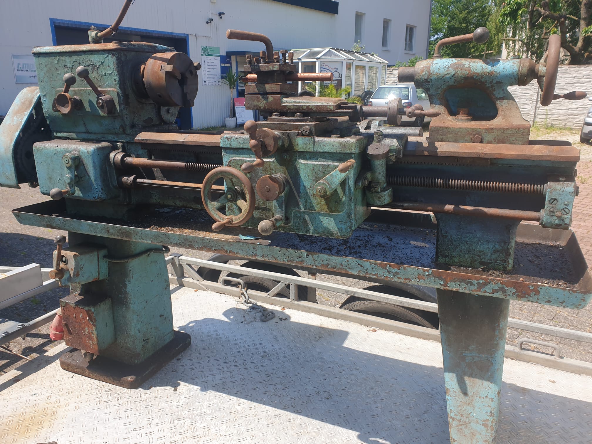
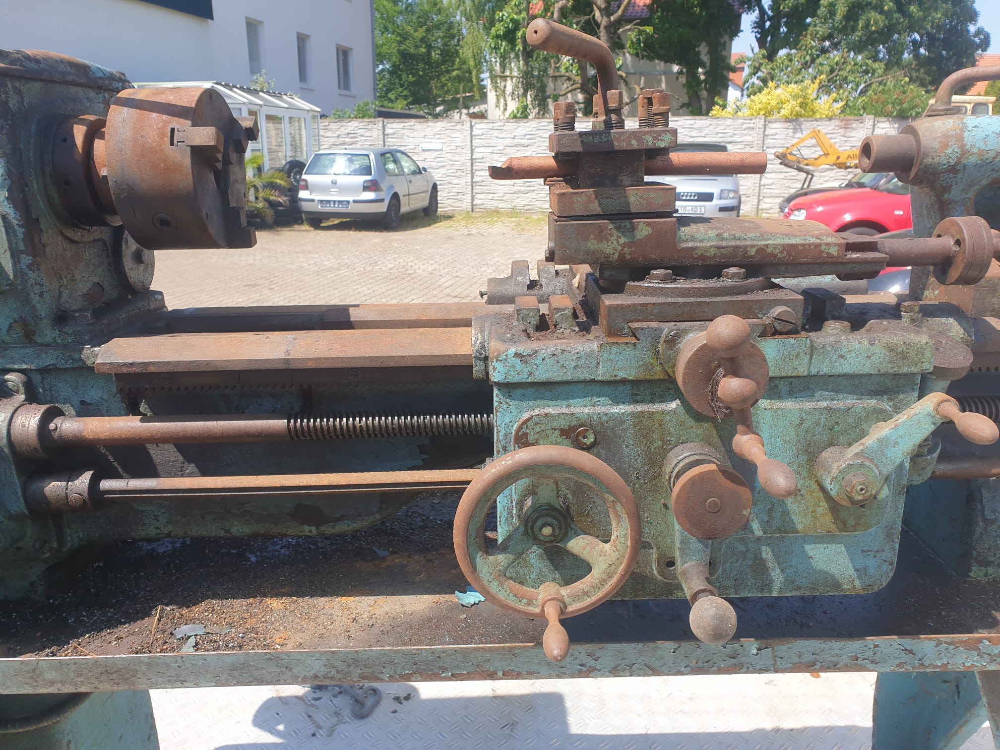
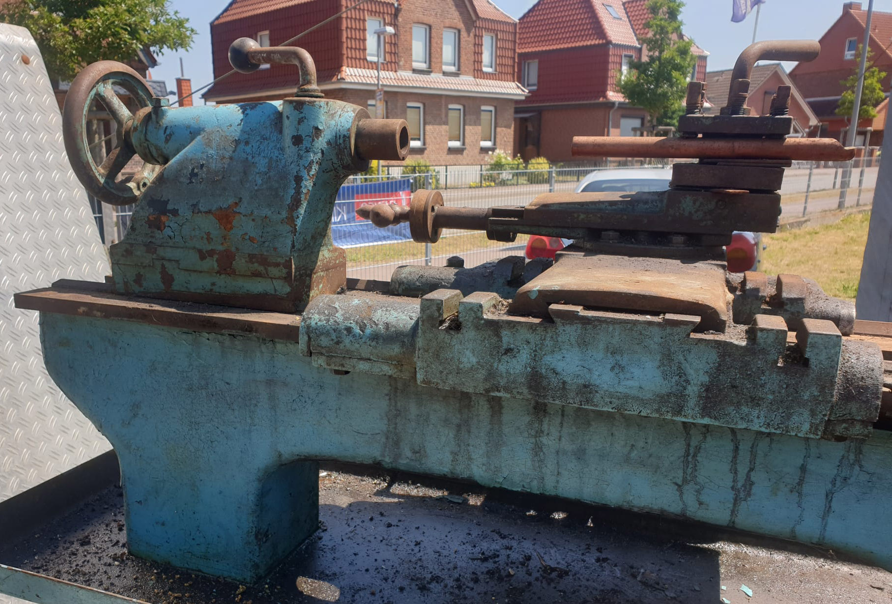
With a centre height of 6.5 inches, and a capacity between centres of 39 inches, the Robot was of simple but rugged construction (made to Schlesinger limits) and incorporated many design refinements to ensure long life and stability in operation. Hardened to between 200 and 220 Brinell, the bed carried V and flat ways and was fitted with a detachable gap section as standard; with the gap bridge removed material up to 19.25 inches in diameter and 5.5 inches thick could be turned on the standard faceplate.
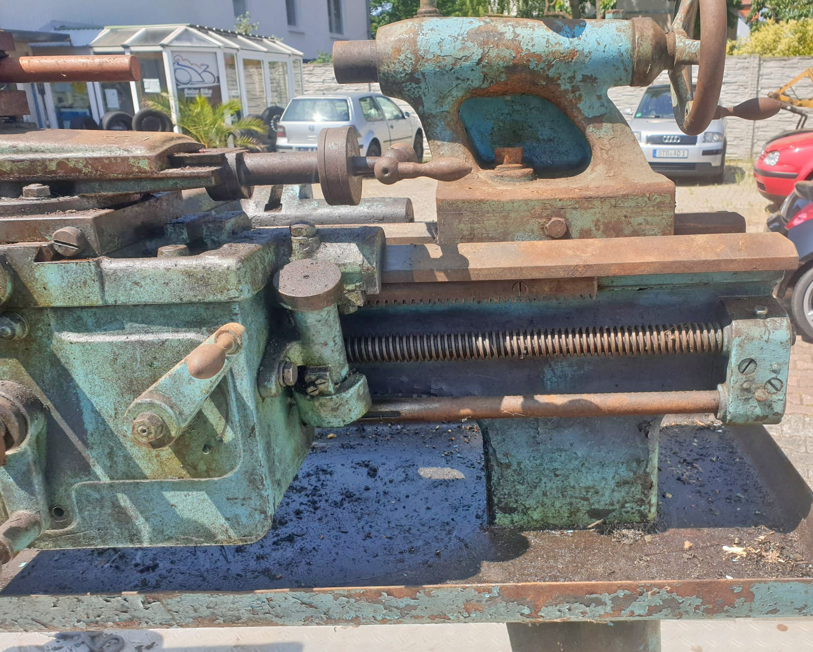
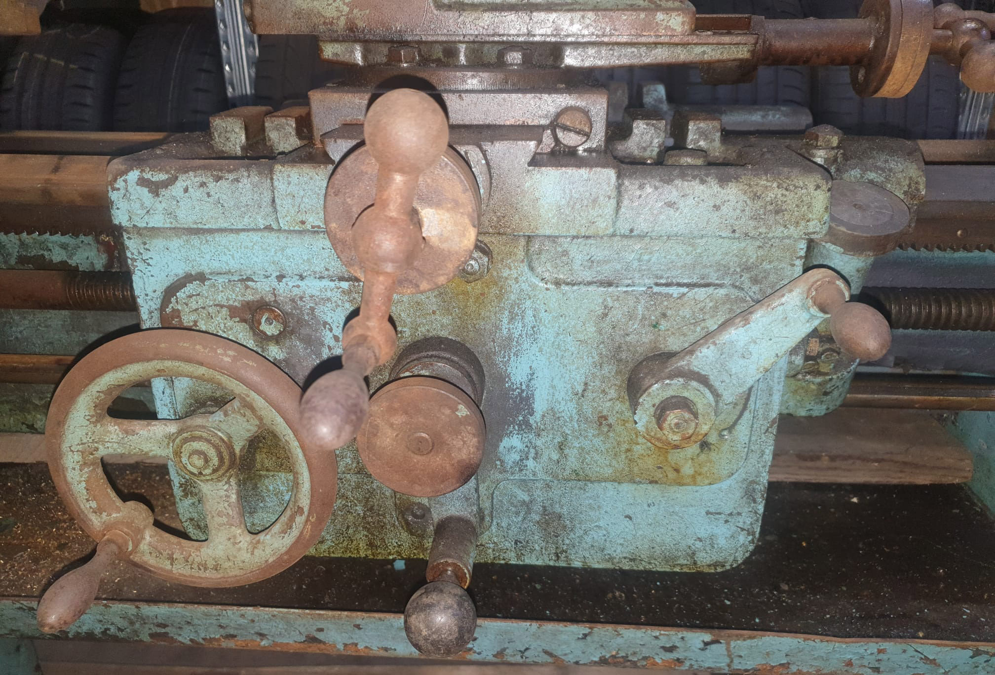
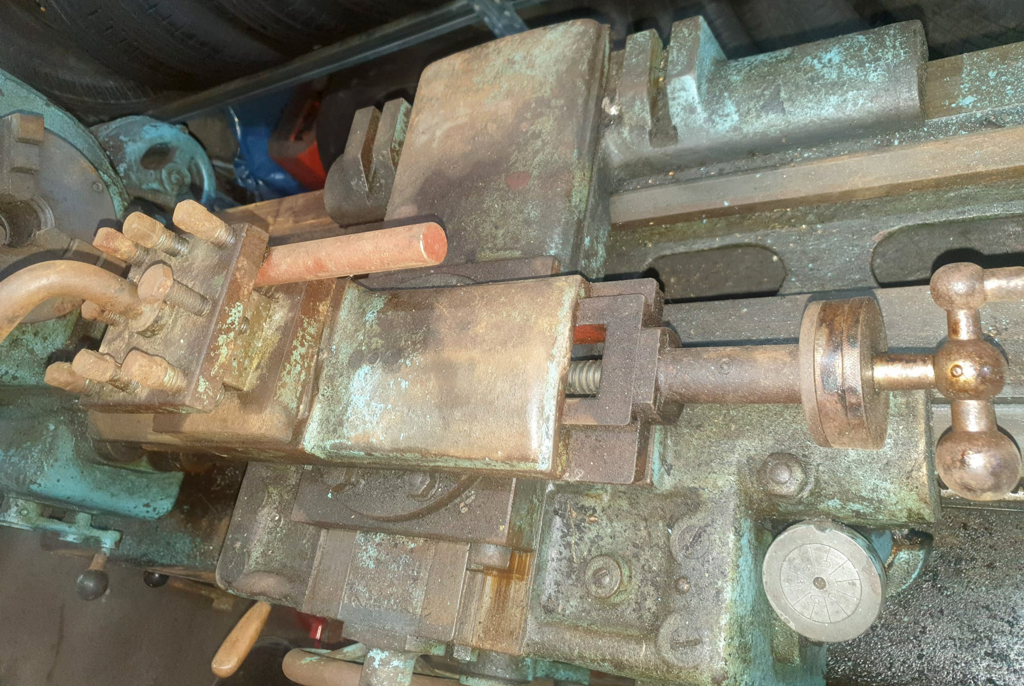
Heavily built, the carriage was provided with a saddle carrying cast-in T slots on each of its wings; the compound slide rest had proper, taper-adjustable gibs and the bracket supporting the end of the cross feed screw (held in place by four screws) was cut down level with the top of the ways to allow the cross slide extra travel by coming forwards until it abutted against the inner face of the micrometer-dial boss. Engineered by mounting the micrometer dial on the end of an extended bracket, the top slide had an unusually long travel and, to ensure that the slide was held firmly to the cross slide when moved to the limits of its travel, four instead of the usual two clamping bolts were fitted. The compound slide rest handles were of the elegant "balanced" type that, although pleasant to use on a small lathe, might have been considered a little hard on the hands when heavier cuts had to be taken on a lathe of this capacity. A 4-way toolpost was fitted as standard.
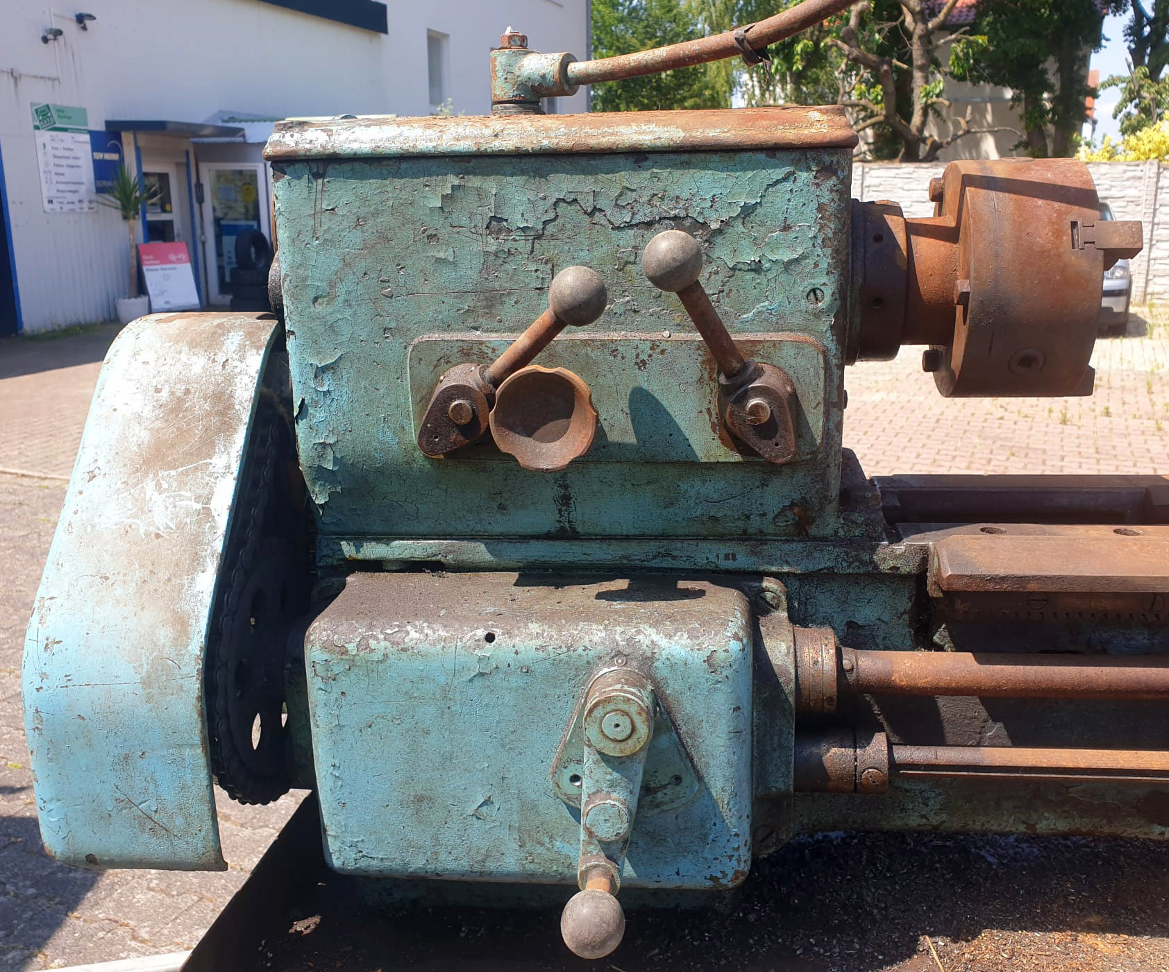
The locking of the carriage to the bed was taken care of by a long plate fitted underneath the front right-hand saddle wing and clamped tight by a conveniently placed, permanently-fitted handle. The apron was of double-wall construction and completely enclosed; an oil bath was provided in the base to lubricate the gears and shafts by splash, but no provision was made to pump this oil to the ways of the cross slide or bed. The arrangement for power feeds and screwcutting was unusual with, strangely, only four rates of sliding and surfacing feed available generated by a separate power shaft running parallel to the leadscrew and driven by a sprocket and "silent chain" from the headstock; the reason for this design remains obscure, most other makers being content to use changewheels to drive a two or three-speed "translation" box on the end of the leadscrew from which a separate power feed for sliding and surfacing could be taken. The selection of sliding or surfacing feeds on the Robot was by an apron-mounted downwards-pointing quadrant lever with a spring-loaded location plunger; mounted concentric with the lever's mounting boss was a knurled-edge handwheel that controlled a safety friction clutch by which means the drives were engaged and released. The feeds were reversed by a control on the front face of the headstock that operated an enclosed, tumble-reverse-like mechanism whilst the longitudinal feed could be automatically disengaged by an adjustable stop on the power shaft.
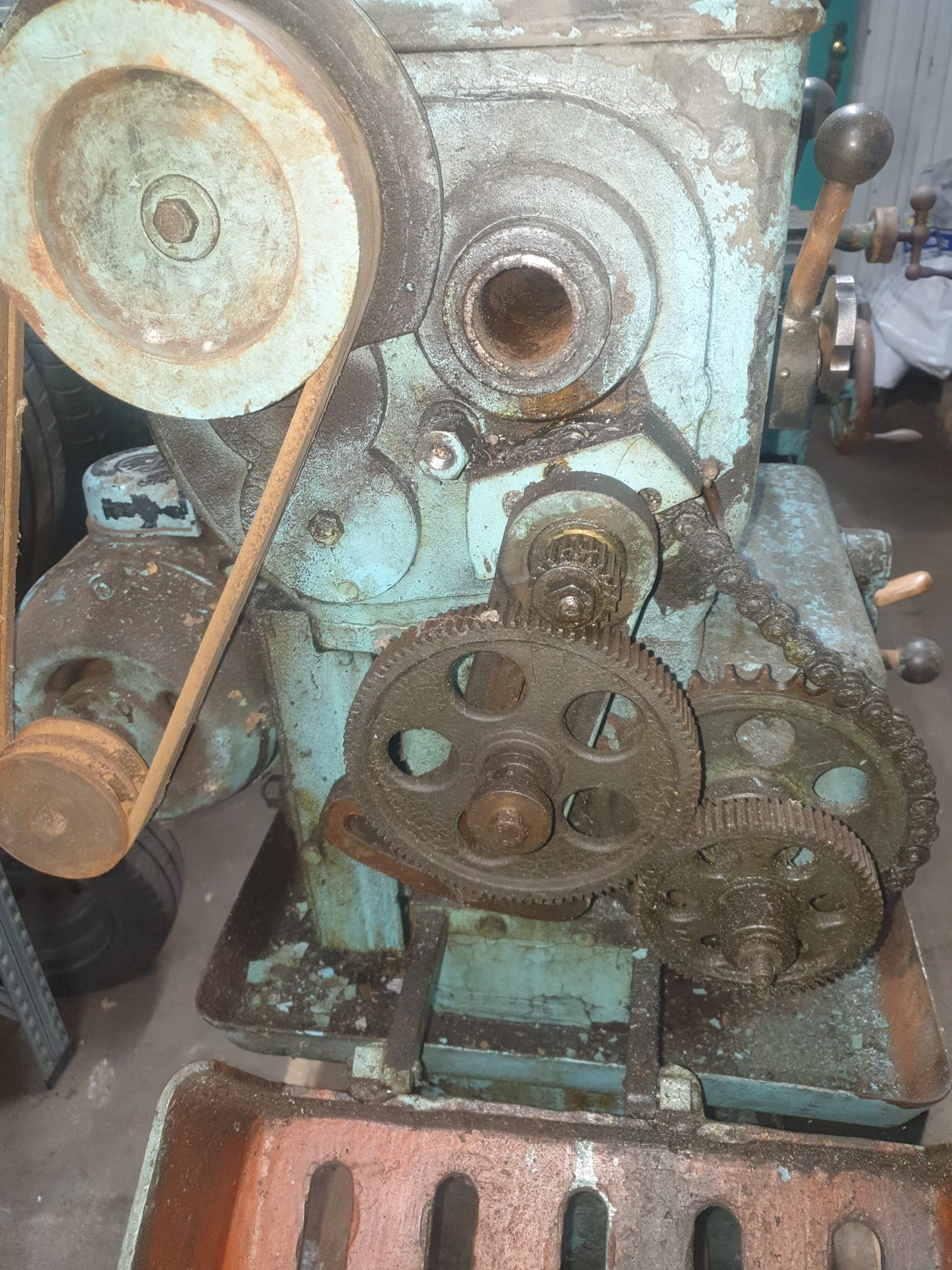
1.125 inches in diameter, the leadscrew was of 4 t.p.i. pitch and could be adjusted for end float by a pair of knurled rings on the outside of the feed box; the tailstock end of the leadscrew was mounted radially to allow for expansion and contraction errors. 17 changewheels were provided - sufficient in number to generate both English and metric threads - and covered by a bottom-hinged cast-iron cover and mounted on a separate quadrant that drove only the leadscrew - A thread-dial indicator was provided amongst the standard equipment.
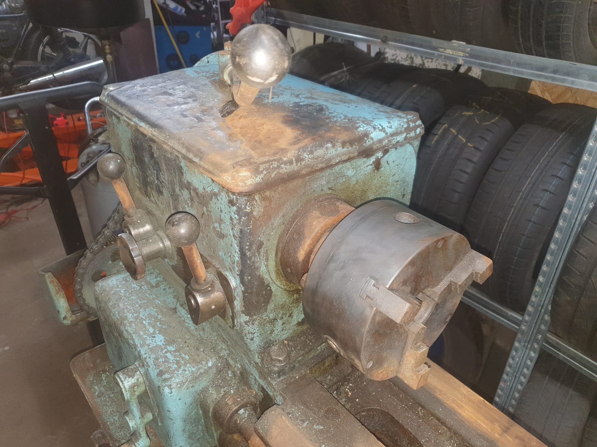
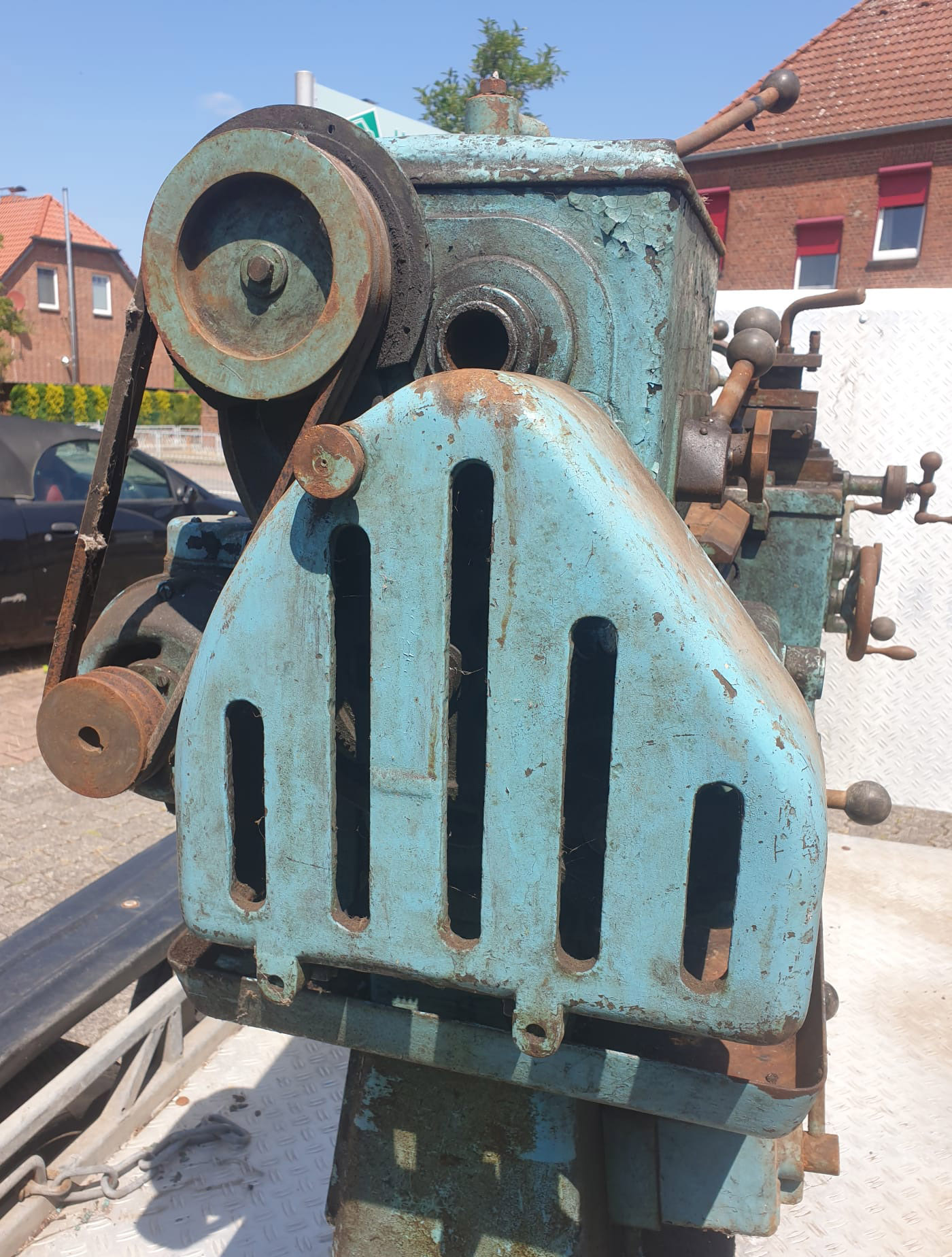
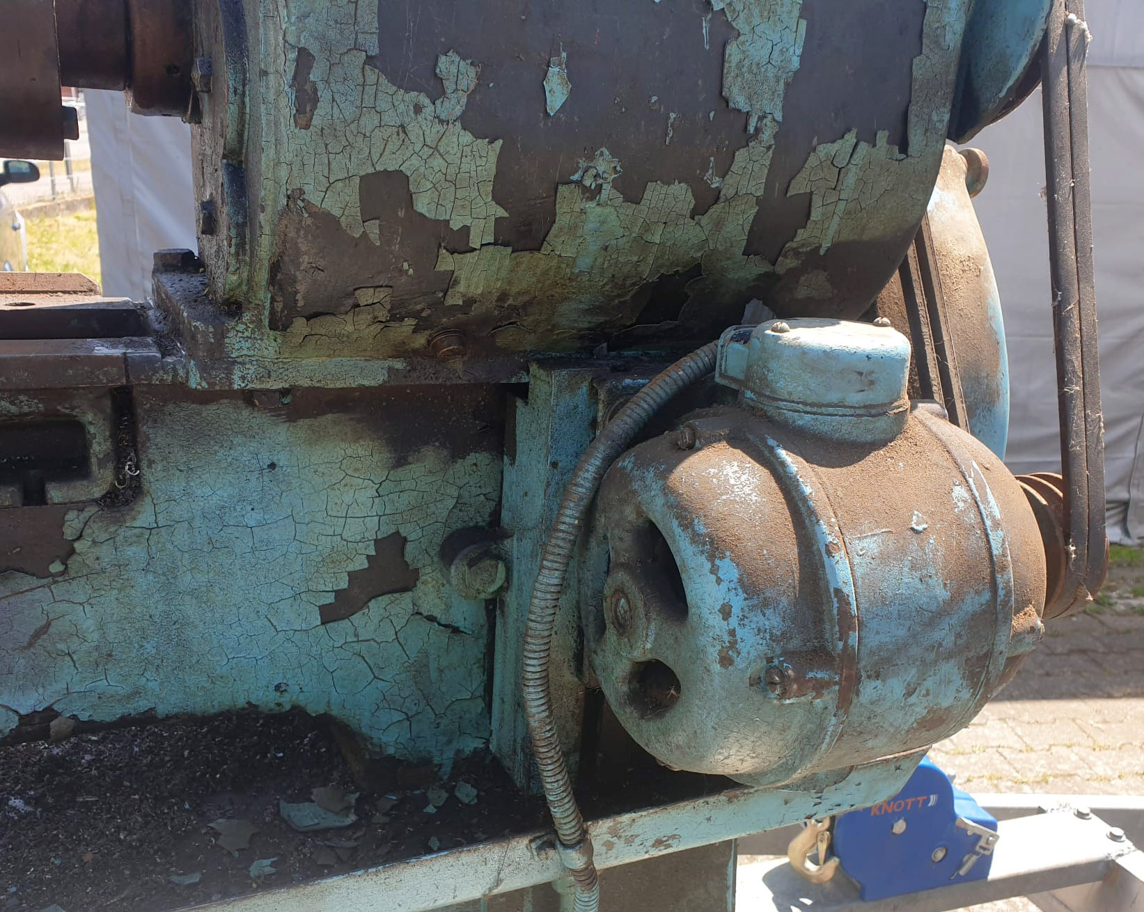
The 6-speed, all-geared headstock was fitted with a clutch and held a 1.5-inch bore spindle running in parallel-bore bronze bearings that were formed with tapered outsides to allow for wear adjustment. The other headstock shafts ran on either ball or roller races and were hobbed from the solid and ground-finished. Spindle speeds were arranged in geometric progression and ran from 47.5 to a rather low top speed of 475 rpm with changes controlled by two levers on the front face of the headstock. The 1 h.p 1440 r.p.m motor was mounted on an adjustable plate, fastened to the back of the headstock-end leg, with power transmitted to the headstock by twin V belts. One of the few options available was a belt-driven suds pump fastened below the motor on the same leg.
Supplied with the lathe were an electric motor and reversing switch, two centres, a 4-way toolpost, threading indicator, fixed and travelling steadies, a large-diameter faceplate, catchplate, 17 changewheels for screwcutting, three ordinary spanners and a set of C spanners to adjust the headstock bearings and leadscrew end float..
|
|