 |
|
|
|
|
|
|
|
|
|
|
|
|
|
|
|
|
|
|
|
|
|
|
|
|
|
|
|
|
|
|
|
|
|
|
|
|
|
|
|
|
|
|
|
|
|
|
|
|
|
|
|
|
|
|
|
|
|
|
|
|
|
|
|
|
|
|
|
|
|
|
|
|
|
|
|
|
|
|
|
|
|
|
|
|
|
|
|
|
|
|
|
|
|
|
|
|
|
|
|
|
|
|
|
|
|
|
|
|
|
|
|
|
|
|
|
|
|
|
|
|
|
|
|
|
|
|
|
|
|
|
|
|
|
|
|
|
|
|
|
|
|
|
|
|
|
|
|
|
|
|
|
|
|
|
|
|
|
|
|
|
E-MAIL Tony@lathes.co.uk
Home Machine Tool Archive Machine-tools for Sale & Wanted
Machine Tool Manuals Machine Tool Catalogues
Belts Books Accessories
Richmond Milling Machines
- by Midgley & Sutcliffe -
Richmond No. 5 Vertical Older Richmond Millers Richmond Turret Miller
Technical & Sales Literature is available for
Richmond millers and drills including the
No. 2 Miller, No. 3 Miller, Turret Miller, 14-60 Miller,
the 03SD Miller and the Universal Dividing Head
Entirely conventional but well made, the Richmond range of industrial milling machines was manufactured by Midgley & Sutcliffe at their Hillidge Works in Hunslet, near Leeds. During the 1930s and 1940s a wide range of models was offered including those listed as the all-geared Models No. 1 and No. 1A; the simpler belt-driven and backgeared "0 Series" as the No. 01, No. 02, No. 03; the even less expensive direct-belt-drive L.H.M. (Light Horizontal) and two vertical types the V.M.1 (Vertical Miller No. 1) and V.H.M. (Vertical High-speed Miller). Production was to reach its zenith during the mid 1950s with a range of Models listed in a simple and logical fashion with the smallest "Plain" horizontal types being the No. 1 followed by the No. 2, No. 3 and No. 4. and the much later 14-60. When fitted with a swing table, the same machines were catalogued as "Universal" types and often supplied as standard with a power-driven universal dividing. Also listed was a single conventional knee-type vertical miller, the No. 3; the No. 5 heavy-duty production vertical, a simplified type, the O3SD and a Turret Milling Machine built with both a single head and, as a "Duplex" model with two heads and a hydraulic copying attachment. The complete head assembly of the turret miller, called the "Hyspeedmil", was also offered as an accessory to mount on the company's horizontal machines.
In addition to their millers, Midgley & Sutcliffe also manufactured a range of radial-arm drilling machines (some times found badged as Qualters 7 Smith), the SR2, SR3, HB3/12, HB4 and a special "girder" radial-arm drill produced as a portable unit consisting of the column and head (less the table) for mounting in-situ on awkward jobs. By the 1970s milling machines had been dropped and production concentrated on drills, a number of more modern types being made amongst which were the well-known and successful Envoy, Herald, Consul and HD4. Starting in 1962, computer-controlled models were introduced, these being subjected to a programme of constant improvement and upgrading with the NC50 of the 1970s equipped with a tape-controlled Plessey system and, in the 1980s, the CNC50 (G.E. 1050HM controls) and NC65M, this being offered with Mark Century 550-MPM control. Some 450 examples of the early NC50 were built and operated by a number of notable UK engineering companies..
|
|
|
|
|
|
|
|
|
|
|
|
|
|
 |
|
|
|
|
 |
|
|
|
|
|
|
An early Richmond No. 1 Plain Horizontal milling machine from the 1940s with a round overarm
|
|
|
|
|
|
|
|
|
|
|
|
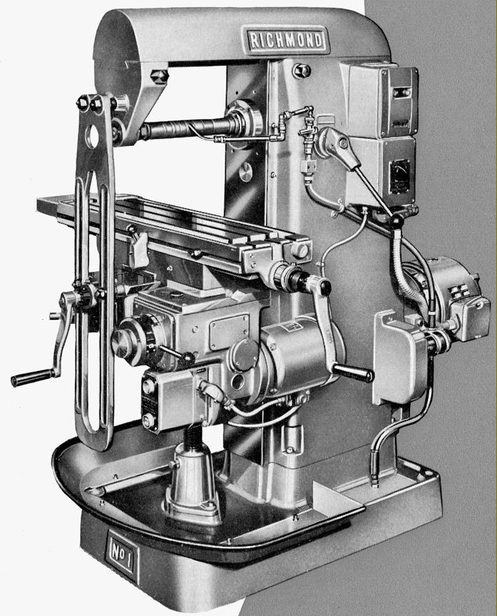
Richmond No. 1
Built as both a "Plain" and "Universal" horizontal milling machine (the latter with a swing table) the Richmond No. 1 had its internally well-ribbed, vibration-resistant column and the coolant-holding base cast in a strong, close-grained iron. Equipped with three 9/16" (14 mm)T-slots on a centre distance of 2.125" (54 mm) and a surround moat equipped with drain strainers for the collection of coolant, the 26" x 8" (660 mm x 203 mm) table had a longitudinal travel by hand and under power of 16" (406 mm), in traverse of 6" (152 mm) and vertically through an open, unprotected telescopic screw of 16.5" (418 mm) - the latter pair of movements being by hand only and the longitudinal power feed set in one direction: left to right. Good-sized micrometer dials were fitted, these being satin-chrome plated and graduated to read within 0.001", and all sliding surfaces (table, knee and saddle), ground finished and hand scraped.
Drive to the table came via a universally-joined, telescopic shaft of the "carden" type from a 3-speed gearbox on the right-hand face of the column, the box being connected to the miller's main drive system by chain through a pair of large and small sprockets held within a cast-iron housing and continuously lubricated by a siphon oil well system. Harking back to a design used by Midgley & Sutcliff in the 1930s, the sprockets were interchangeable and so doubled the three speeds of the gearbox to six. However, obtaining the alterative set meant having to remove the (easily opened) cover and swap the sprockets over - a simple but very messy job. The full range of table feed-rates varied from a low of 0.005" (0.127 mm) to a high of 0.048" (1.22 mm) per revolution of the spindle. At the table-end of the drive connection to the longitudinal feed screw was through the usual type of drop-out worm and wheel, the former being hardened and the latter in bronze running in an oil bath. Equipped with clutched handles, the longitudinal table feed screw had at its right-hand end (to improve the speed of operation), a 3 : 1 quick-return mechanism turned by a large diameter full-circle handwheel with the left-hand end fitted, like the cross and vertical feed screws, with a long crank handle.
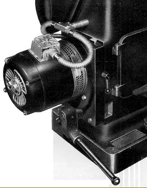
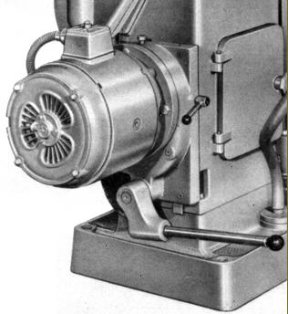
Supplied completely wired and ready to run, the miller could be had as the "Type 1" with a 1.5 h.p. 1-speed 3-phase motor running at either 1000 r.p.m. or 1500 r.p.m. or as the "Type 2" with a 2-speed 750/1500 r.p.m. motor, all types being controlled by a flush-mounted no-volt release push-button starter and the appropriate selector switches Drive on both was identical with the motor flange mounted against the rear face of the column and carrying on its spindle a quiet-running "Fabroil" gear that engaged with a steel gear on a ball-bearing supported countershaft. From the countershaft the drive passed upwards using a wide, flat belt running over 3-step cone pulleys that gave, in conjunction with backgear, six speeds from 34 to 400 r.p.m. with the 1000 r.p.m. motor; from 51 to 600 r.p.m. with the 1500 r.p.m. unit and 12 speeds from 26 to 600 r.p.m. using the 2-speed version. In order to simplify changes of speed, on both the plain and Universal models the motor and its associated countershaft were mounted together on a bracket that could be unclamped, moved up using a long lever connected to rack-and-pinion gearing, the now slackened belt moved to a new position, the clamp released and the bracket allowed to fall back into place. An extension to the countershaft spindle carried a V-pulley, the drive from which (covered by an aluminium guard) drove the geared coolant pump.
Manufactured in an Alloy steel and hardened on its No. 3 Morse taper nose (though other fitting could be supplied if required), the main spindle ran in a pair of Timken taper roller bearings at the front and a roller journal bearing at the rear. The slow-speed backgear mechanism was in steel with the remote gears carried on a high-carbon, steel shaft. Of robust proportions, the overarm was of the dovetail type (replacing the much less effective round unit of earlier years) and locked in place by two clamps. A pair of adjustable braces was provided these, in the usual way, being connected to the front of the knee and the face of the overarm.
A number of accessories were offered including a tool cabinet; a plain, swivelling vertical head and another, universal type, with a double swivel; a 2.5-inch stroke slotting attachment; a 10-inch hand-operated rotary table; a 4.5-inch swivel-base machine vice; collet chucks; a variety of cutter-holding arbors; Low-Vo light unit; a plain dividing head, and, on the "Universal" model only, a 4.5-inch Universal dividing head driven from gearing connected to the table's longitudinal feed screw. Also available were 4-inch and 5-inch 3-jaw chucks with backplates to fit the dividing heads - these usually being supplied by Pratt.
|
|
|
|
|
|
|
|
|
 |
|
|
|
|
|
|
|
|
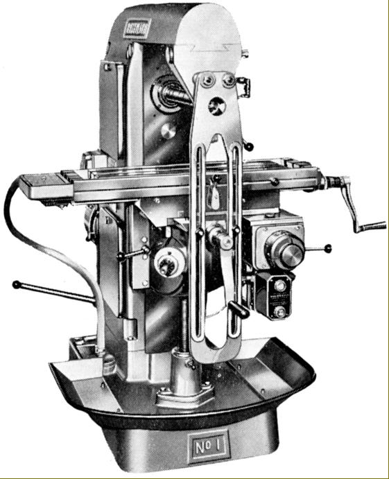
Late-model Richmond No. 1 Plain Horizontal milling machine from the 1950s with a dovetail overarm
|
|
|
|
|
|
|
|
|
|
|
 |
|
|
 |
|
|
|
|
|
|
|
|
|
|
|
|
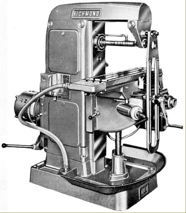
Late-model Richmond No. 1 Plain Horizontal milling machine from the 1950s with a dovetail overarm
|
|
|
|
|
|
|
|
|
 |
|
 |
|
|
|
|
|
|
|
|
|
|
|
|
|
 |
|
|
|
|
|
|
|
|
|
|
|
|
|
|
|
|
|
|
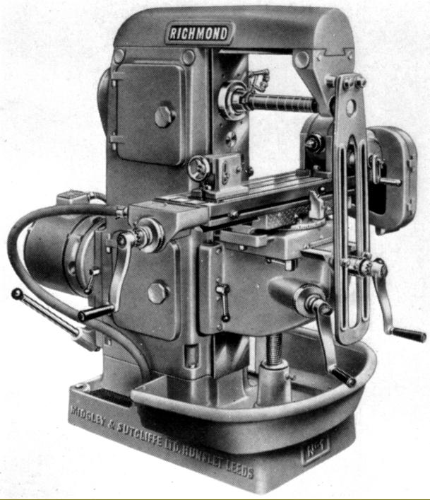
Late-model Richmond No. 1 Universal Horizontal milling machine with a swing table
|
|
|
|
|
|
|
|
|
|
|
|
|
|
|
|
|
|
 |
|
 |
|
|
|
|
|
 |
|
|
|
|
|
|
|
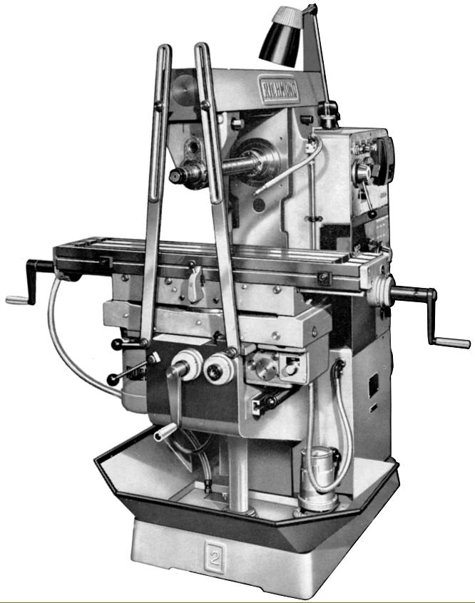
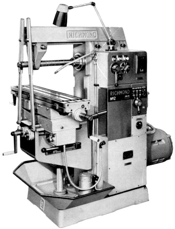
Richmond No. 2 Plain Horizontal Milling Machine with more modern lines from the 1960s
|
|
|
|
|
|
|
|
|
|
|
Richmond No. 2
Built as both a "Plain" and "Universal" horizontal milling machine (the latter with a swing table) the No. 2 Model was originally listed as the Model 02 during the 1940s and early 1950s but was then dropped until it appeared again, completely redesigned as a more angular, modern machine with an entirely novel drive system, in the early 1960s.
Equipped with three 9/16" (14 mm) T-slots on a centre distance of 2.125" (54 mm) and a surround moat equipped with drain strainers for the collection of coolant, the 40" x 9" (1016 mm x 220 mm) table had a longitudinal travel by of 24" (610 mm), in traverse of 9" (229 mm) and vertically through an enclosed telescopic screw of 16" (406 mm) - the former pair of movements being by hand or power and latter by hand only.
The longitudinal power feed was set in one direction of travel only, from right to left. Good-sized micrometer dials were fitted, these being satin-chrome plated and graduated to read within 0.001", and all sliding surfaces (table, knee and saddle), ground finished and hand scraped.
Drive to the table came via a universally-joined, telescopic shaft of the "carden" type from a 3-speed, lever-change gearbox on the right-hand face of the column, the box being connected to the miller's main drive system by an enclosed chain and continuously lubricated by a siphon oil well system. In order to double the number of feeds available the gearbox was fitted with easily changed "pick-off" gears the rates of feed spanning 0.003" to 0.29" per revolution of the spindle. At the table-end of the drive connection to the longitudinal feed screw was through the usual type of drop-out worm and wheel, the former being hardened and the latter in bronze and running in an oil bath. Equipped with clutched handles, the longitudinal table-feed screw could be specified with a rapid-return mechanism powered by a separate motor flange mounted to the underside of the knee's left-hand side.
Manufactured in an Alloy steel and hardened on its 40 INT nose (though other fitting could be supplied if requested, the main spindle ran in a pair of angular contact bearings at the front and single row roller bearing at the rear. Drive to the spindle on both versions was identical with a 3 h.p., four-speed motor flange mounted against the rear face of the column and driving, though spur gears, a ball-bearing supported countershaft. From the countershaft the drive passed upwards using "Brammer" link belts to the spindle, the drive having, in conjunction with a backgear mechanism, 8 speeds from 43 to 800 r.p.m. As control of the spindle was simply by a rotary knob to selected the desired motor speed in conjunction backgear, there was no need on this model - as on the No. 1 - for the countershaft belt system to be adjustable in any way.
Of robust proportions, the overarm was of the dovetail type (replacing the much less effective round type used during the 1930s and 1940s) and locked in place by two clamps. A pair of adjustable braces was provided with these, in the usual way, connected to the front of the knee and the face of the overarm.
The usual range of made-in-house accessories were offered including a tool cabinet; a plain, swivelling vertical head and another, universal type, with a double swivel; a 2.5-inch stroke slotting attachment; a 10-inch hand-operated rotary table; 4.5-inch and 6-inch swivel-base machine vices; a plain dividing head; collet chucks; a variety of cutter-holding arbors; Low-Vo light unit; a 5-inch plain dividing attachment and, on the "Universal" model only, a 5-inch Universal dividing head driven from gearing connected to the table's longitudinal feed screw. 5-inch and 6-inch 3-jaw chucks for the dividing heads with backplates could also be supplied, these usually being supplied by Pratt..
|
|
|
|
|
|
|
|
|
|
|
 |
|
|
|
|
|
Richmond No. 3
Offered as both a "Plain" and, with a swing table, a Universal type, the Richmond No. 3 was the smallest machine in the Company's 1950s and 1960s range with an all-geared drive system. Robustly built, the miller was constructed around a well-ribbed, vibration-resistant column in a close-grained cast iron with the coolant supply held in the base foot.
Equipped with three 9/16" (14 mm) T-slots on a centre distance of 2.5" (63 mm) and a surround moat equipped with drain strainers for the collection of coolant, the 48" x 11" (1219 mm x 279 mm) table had a longitudinal travel by hand and under power of 30" (762 mm), in traverse of 8" (203 mm) and vertically through an enclosed telescopic screw of 16" (406 mm) - all movements being fitted with power feeds and rapids available as an extra-cost option. When fitted, the rapids were driven by a separate, 1 h.p. motor flange mounted to the underside of a gearbox bolted to the right-hand face of the knee. Control was by a single, spring-loaded lever that was raised to engage and released to disengage the drive with both longitudinal and traverse set at 100 inches per minutes and vertical set to be half as fast.
Twelve rates of power feed were fitted, driven from an enclosed gearbox mounted on the right-hand face of the column and protected from damage by an adjustable, spring-loaded slipping clutch. Gears were all in a tough, nickel-chrome steel with the sliding elements mounted on ground-finished multi-splined shafts turning in ball races. Control of the feed rate was by an easy-to-operate, direct-reading dial and the drive taken to the table via a universally-joined, telescopic shaft of the "carden" type. At the table-end of the drive connection to the longitudinal feed screw was through the usual type of drop-out worm and wheel, the former being hardened and the latter in bronze and running in an oil bath. A choice of two speed ranges, standard and fast, was offered: on longitudinal and traverse the former ran from 0.45" to 12.5"/min (11.5 to 317.5 mm/min) and the latter from 0.9" to 25"/min (23 to 635 mm/min). In both cases the vertical rate set was set, sensibly, to be half as slow.
Adjustable knock-off stops were, of course, fitted to all axes of feed, and the table and knee feed controls were simple, directional levers all within easy reach of a front-standing operator: moving the levers left and right, or up and down, producing the corresponding direction of movement. Good-sized micrometer dials were fitted, these being satin-chrome plated and graduated to read within 0.001", and with all sliding surfaces (table, knee and saddle), ground finished and hand scraped.
Manufactured in a nickel-chrome steel hardened and ground all over including the 40 INT nose (other fittings could also be specified), the main spindle ran in high-precision bearings by Gamet, a company in the 600 Group, with a duplex type at the front and a single pre-loaded taper roller bearing at the rear - these being of the same superior quality as used, for example, in Colchester lathes. Speed changes were from a gearbox built into the main column that used gears made from nickel-chrome steel, hardened and ground on their tooth form and running on ground, splined shafts in a tough alloy steel. Using what the makers described as high-grade ball and roller bearings throughout, the box was positively lubricated by filtered oil from a mechanical pump that directed its supply through copper tubes to the spindle bearings and gear mesh points. Twelve spindle speeds in geometrical progression from 20 to 1000 r.p.m. were provided, these being selected by a simple, direct-reading lever-and-disc control. Power came from a single-speed, 1400 r.p.m. 3-phase, 400/440 volt, 5 h.p. motor that, because the column was so massive, could be mounted inside its body with the drive taken by multiple V-belts to a constant-speed pulley that ran at 600 r.p.m. The pulley was connected to the main drive shaft through a double, multi-disc clutch-cum-brake operated by duplicated levers, one being positioned at each side of the column near the top that allowed the operator to control the machine from either the left or right-hand side. Raising a lever started the machine while pulling it down disengaged the drive and applied the brake.
The usual range of made-in-house accessories were offered including a tool cabinet; a plain, swivelling vertical head and another, universal type, with a double swivel; a 3-inch stroke slotting attachment; 10-inch and 12-inch hand-operated rotary tables; 4.5-inch and 6-inch swivel-base machine vices; a plain dividing head; collet chucks; a variety of cutter-holding arbors; Low-Vo light unit; a 6-inch plain dividing head and, on the "Universal" model only, a 6-inch Universal dividing head driven from gearing connected to the table's longitudinal feed screw. 5-inch and 6-inch 3-jaw chucks with backplates for the dividing heads could also be supplied, these usually being supplied by Pratt.
|
|
|
|
|
|
 |
|
|
|
|
|
|
 |
|
|
|
|
|
|
|
Richmond No. 3 Universal Horizontal Milling Machine with swing table
|
|
|
|
|
|
|
|
|
|
|
 |
|
|
|
 |
|
|
|
|
|
|
|
|
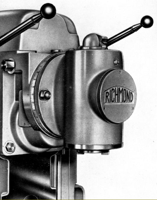
Plain single-swivel vertical head without quill feed as used on many versions of Richmond horizontal milling machines
|
|
|
|
|
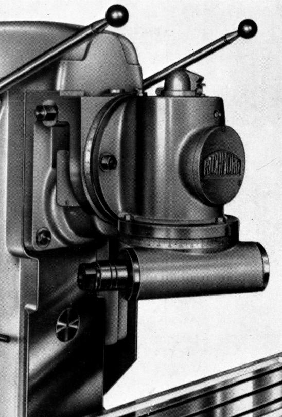
Slotting head of the type used on many Richmond horizontal milling machines
|
|
|
|
|
|
|
|
|
|
|
 |
|
|
 |
|
|
|
|
|
|
|
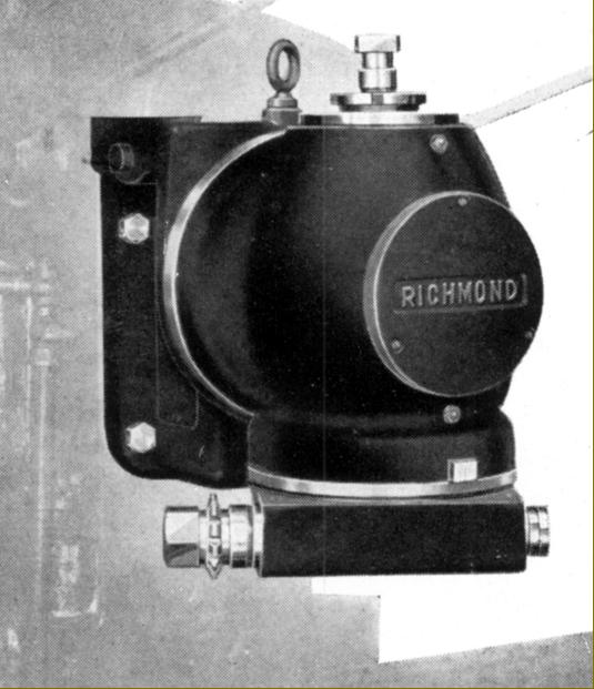
Early version of the Universal (double-swivel) vertical head of the type
used on many Richmond horizontal milling machines
|
|
|
|
|
|
|
|
|
|
|
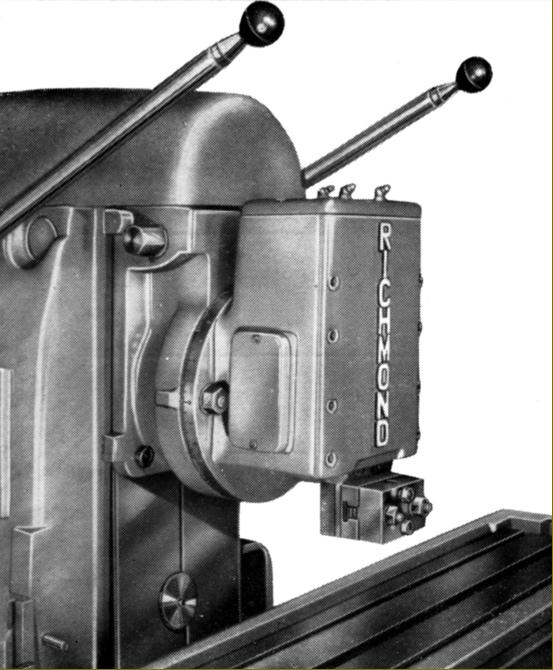
Late-type Universal (double-swivel) vertical head of the type used on many Richmond horizontal milling machines
|
|
|
|
|
|
|
 |
|
|
|
|
|
|
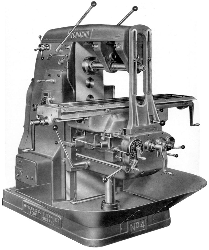
Richmond No. 4 Plain Horizontal Milling machine
|
|
|
|
|
|
|
|
|
Richmond No. 4
Produced in the usual two forms as a "Plain" and, with a swing table, a Universal model, the Richmond No. 4 had very little more capacity than the No. 3 but was heavier by around 1/2 ton and intended for particularly arduous factory work. Robustly built, the miller was constructed around a well-ribbed, vibration-resistant column in a close-grained cast iron with the coolant supply held in the base foot.
Equipped with three 9/16" (14 mm) T-slots on a centre distance of 2.5" (63 mm) and a surround moat equipped with drain strainers for the collection of coolant, the 50" x 12" (1269 mm x 305 mm) table had travels identical to those on the No. 3 i.e. longitudinal travel by hand and under power of 30" (762 mm), in traverse of 8" (203 mm) and vertically through an enclosed telescopic screw of 16" (406 mm) - all movements being fitted as part of the standard specification with both power and rapid feeds, the latter at the rate of 100" per minute on longitudinal and across and at half that rate vertically. The arrangement of the rapids was interesting with the ability to engage the feed (by depressing a spring-loaded lever) so long as 1000 r.p.m. 2 h.p. feed motor was running - it being unnecessary to have the spindle turning - and with the refinement of an over-run clutch that allowed rapids to be used simultaneously with the ordinary feeds e.g. on a workpiece with gaps it was possible to jump across these and, upon release of the rapids' control lever, immediately return to the normal rate.
Twelve rates of power feed were available, from 0.5" to 20" (12 mm to 508 mm) per minute on longitudinal and in traverse with vertical set to be at half that rate. Drive came from a gearbox built into the solid-top knee and fitted with gears in a tough, nickel-chrome steel with the sliding elements mounted on ground-finished, multi-splined shafts turning in ball races. Control of the feed rate was by Cincinnati-like "dial-type" control, mounted on the front face of the knee, that worked in both directions - a single turn of the crank handle selecting the next higher or lower speed. Adjustable knock-off stops were, of course, fitted to all axes of feed with the table and knee-feed controls simple, directional levers duplicated for use from either the front or rear and so allowing the operator to manipulate the machine from front and side while retaining a full view of the cutting tool and workpiece. Good-sized micrometer dials were fitted, these being satin-chrome plated and graduated to read within 0.001", and with all sliding surfaces (table, knee and saddle), ground finished and hand scraped.
Manufactured in a nickel-chrome steel that was hardened and ground all over, including the 40 INT nose (other fittings could also be specified), the main spindle ran in a pair of high-precision, taper roller bearings by Timken at the front, a centre support ball bearing and, at the rear, a single roller bearing. Speed changes were from a gearbox built into the main column that used gears made from nickel-chrome steel, hardened and ground on their tooth form and running on hobbed, splined shafts in a tough alloy steel. Using what the makers described as high-grade ball and roller bearings throughout, the box was positively lubricated by filtered oil from a mechanical pump that directed its supply through copper tubes to the spindle bearings and gear mesh points. Sixteen spindle speeds in geometrical progression from 20 to 700 r.p.m. were provided, these being selected by a mechanism identical to that used for the table feeds, the dial being positioned on the left-hand face of the column together with a separate lever to mechanically reverse the spindle rotation.
Power came from a 1400 r.p.m. 3-phase, 400/440 volt, 7.5 h.p. motor that, because the column was so massive, could be mounted inside its body with the drive taken by multiple V-belts to a constant-speed pulley that ran at 600 r.p.m. The pulley was connected to the main drive shaft through a double, multi-disc clutch-cum-brake operated, on early versions, by duplicated levers, one being positioned at each side of the column near the top that allowed the operator to control the machine from either the left or right-hand side. Later models had the clutch levers repositioned in a more convenient position at each side of the knee. Raising a lever started the machine while pulling it down disengaged the drive and applied the brake.
The usual range of made-in-house accessories were offered including a tool cabinet; a plain, swivelling vertical head and another, universal type, with a double swivel; a 3-inch stroke slotting attachment; 10-inch and 12-inch hand-operated rotary tables; 4.5-inch and 6-inch swivel-base machine vices; a plain dividing head; collet chucks; a variety of cutter-holding arbors; "precise" combination distance pieces, Low-Vo light unit; a 6-inch plain dividing head and, on the "Universal" model only, a 6-inch Universal dividing head driven from gearing connected to the table's longitudinal feed screw. 5-inch and 6-inch 3-jaw chucks with backplates for the dividing heads could also be supplied, these usually being supplied by Pratt.
|
|
|
|
|
|
|
 |
|
|
|
|
|
|
|
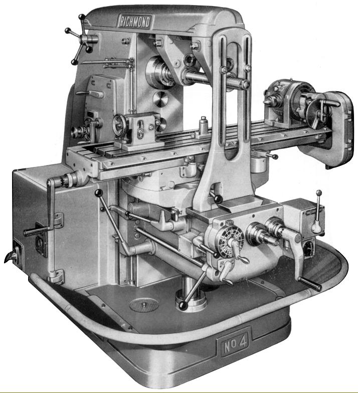
Richmond No. 4 Universal Horizontal Milling Machine with swing table
|
|
|
|
|
|
|
|
|
|
 |
|
|
|
|
|
|
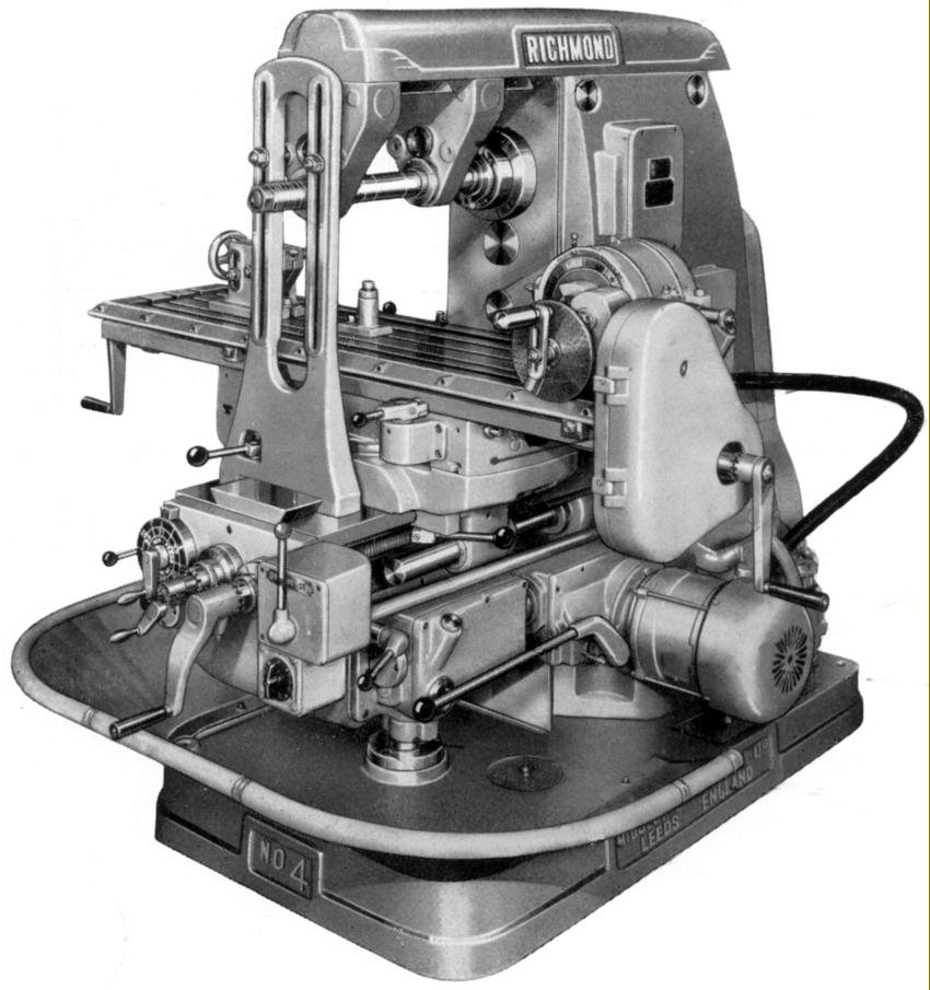
Richmond No. 4 Universal Horizontal Milling Machine with swing table and fitted with a powered indexing head
|
|
|
|
|
|
|
|
 |
|
|
 |
|
|
|
|
|
|
|
|
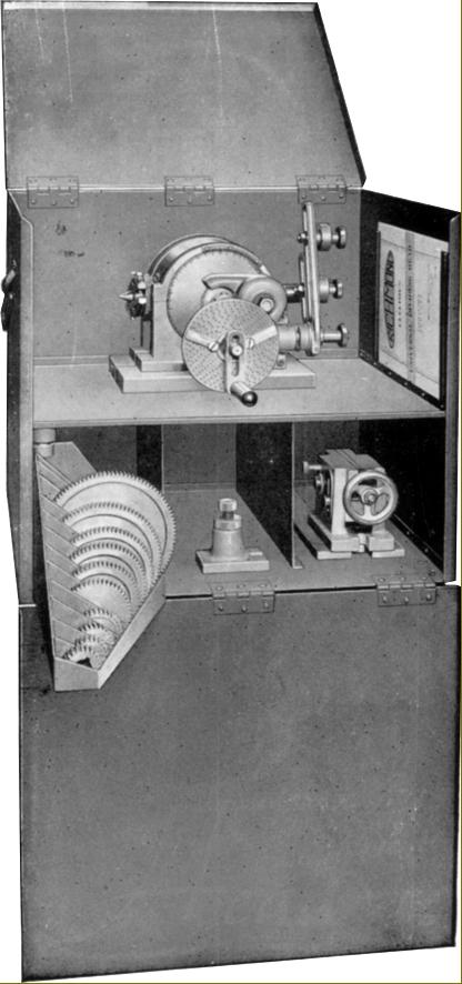
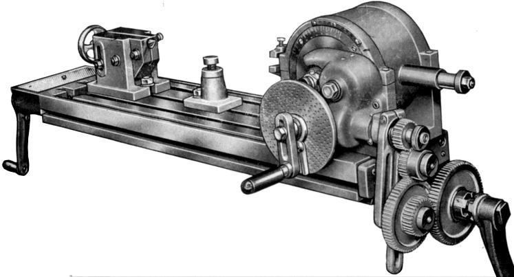
Early Richmond Universal Dividing Head showing the exposed gear train from the longitudinal feed screw
|
|
|
|
|
|
|
|
|
 |
|
|
|
|
|
|
|
|
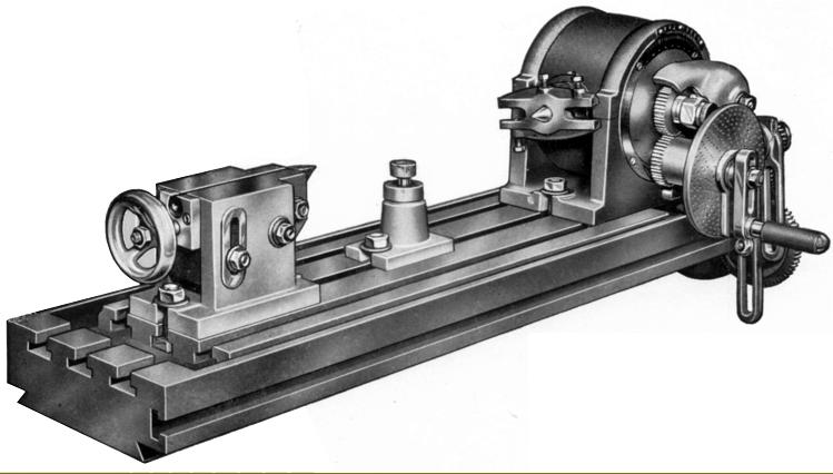
Tailstock-end view of the Universal dividing attachment
|
|
|
|
|
|
|
|
|
|
|
 |
|
 |
|
|
|
|
|
|
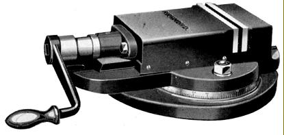
Typical Richmond swivel-base machine vice
|
|
|
|
|
|
|
|
 |
|
|
|
|
|
|
|
|
|
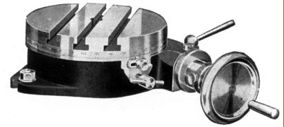
Richmond 8-inch rotary table as sold during the 1930s and 1940s
|
|
|
|
|
 |
|
|
|
|
|
|
 |
|
|
|
|
|
|
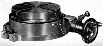
Richmond 8-inch rotary table as sold during the 1950s and 1960s
|
|
|
|
|
|
|
|
|
|
|
|
|
|
An early Richmond "plain" dividing attachment with tailstock
|
|
|
|
|
|
|
|
|
 |
|
|
|
|
 |
|
|
|
|
|
|
|
|
|
|
|
|