|
Introduced in 1977 as the first of the stand-alone, Myford-branded milling machines, in later years the VM-C was to be joined by two additional models, the VM-E and VM-F. While all three shared the same basic design, some castings and the main element of the vertical head, the VM-F was sufficiently different to merit description in a separate article that can be found lower down the page.
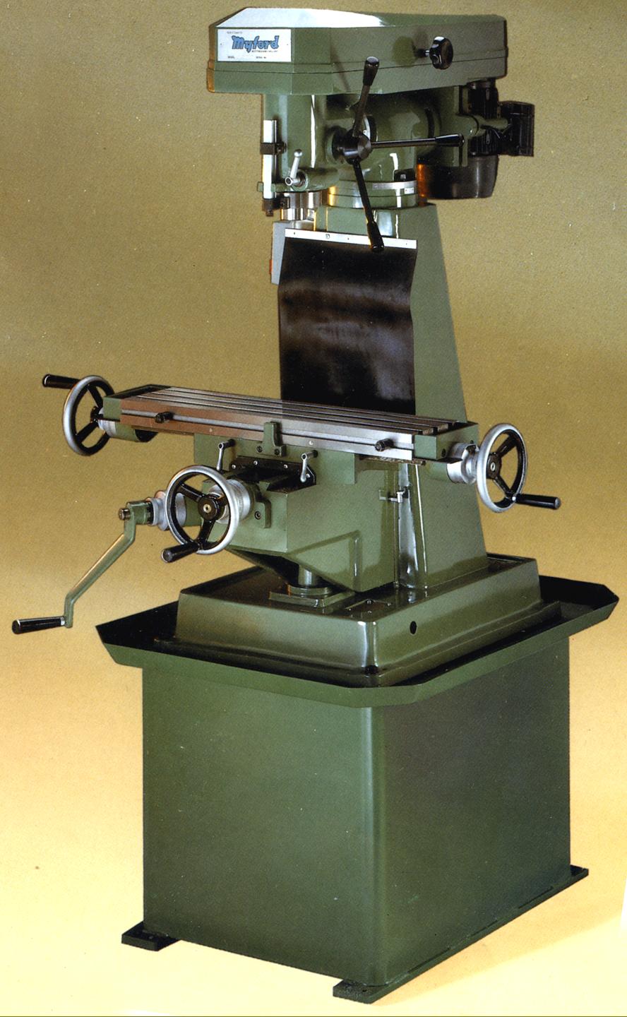
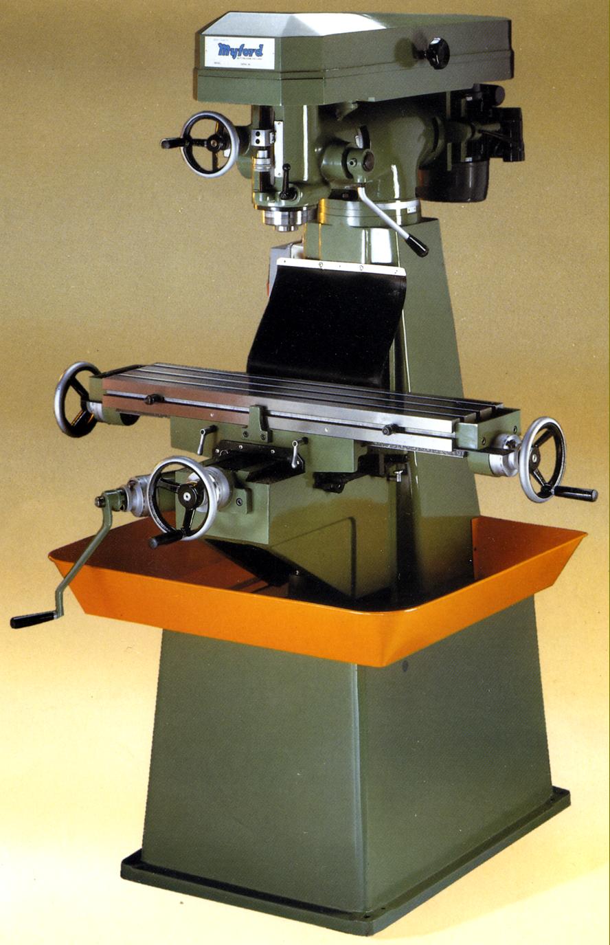
Both the VM-C and VM-E had their main column mounted on a decently sized (and hence stable base), fabricated from heavy sheet-steel (with a very shallow chip tray) in the case of the former and in cast-iron (with a usefully deep, sheet-steel chip tray) for the latter. The hollow, box-section cast-iron column carried a turret head that could be swung, according to the Taiwanese manufacturers, 120° each side of central in the horizontal plane and inclined 90° each side of vertical. However the Myford specification, as listed, was more modest claiming a swing of 90° horizontally and an inclination of the head of just 45° each side of vertical. Although resembling a turret-head machine, neither had a sliding ram, a curious omission considering how little extra it would have cost to include and how much more versatility it would have added.
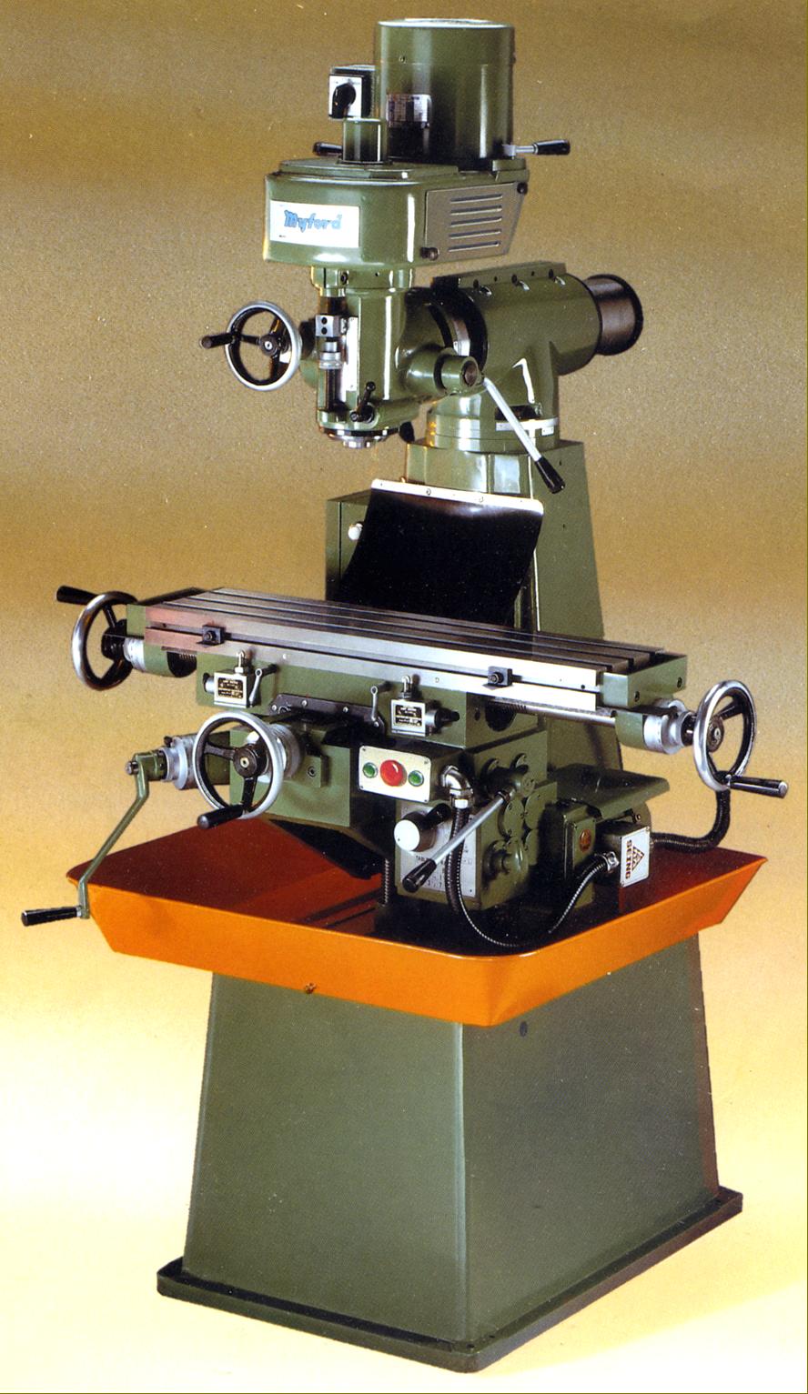
Mounted on a hinged plate at the back, the British-made motor (the other electrical equipment was British, too) was moved by a cam-action release-tighten mechanism that allowed the V-belts to be slackened for changes of speed. From a 3-step pulley on the motor the drive went to a freely floating intermediate 4-step pulley and from there to the 4-step front drive pulley, the latter running in its own double ball races with the splined end of the spindle sliding through its centre. A side-hinged, cast-aluminium cover neatly guarded the complete assembly, closed on early models by a spring catch and on some later versions by a lock turned by a recessed socket-headed bolt. By juggling belt positions, nine spindle speeds could be obtained, these varying, together with the motor power, from model to model and usually being found as follows:
VM-C: ¾ h.p. 1-phase or 3-phase motor giving 160 to 2,540 r.p.m.
VM-E: 1 h.p. 1-phase or 3-phase motor giving 180 to 2,860 r.p.m. In 2003 the VM-E (in line with the VM-B) was offered with an alternative system with the V-belts replaced by a smoother running Poly-V type and a variable speed drive unit fitted. The new set up consisting of a 1.5 h.p. 3-phase motor controlled by a VFD (variable frequency drive or "phase inverter") that gave four separate ranges of 40 to 300 r.p.m., 70 to 525 r.p.m., 228 to 1710 r.p.m. and 400 to 3000 r.p.m. with, of course, speeds within each range able to be set (by a dial control) to whatever level the operator required. Running in ball races - two deep-grove sealed-for-life at the bottom and a single thrust at the top - the spindle was fitted with the popular Bridgeport-type R8 nose so allowing the impecunious amateur owner the chance fit cheap, second-hand tooling and collet holders. The maximum clearance between spindle nose and the inside face of the column (the throat) was 155 mm (6") - though by 2003 a 100 mm (4") raiser block was being offered that, unfortunately, had to be factory fitted.
On the earliest versions, the VM-F was the only version to be equipped with both a lever-operated rapid-action and a fine-feed to the quill, the latter by a micrometer-dial equipped handwheel working through worm-and-wheel gearing. The other models had to make do with just the lever feed and a ruler scale marked in either 80 divisions of 1 mm or 3.5" split into 1/16 ths with, to control the depth of feed, a drill-type vertical stop adjustable by the usual pair of round, knurled-edge nuts. However, by early in the 21st century the fine feed mechanism had become standard on the VM-E as well. As far as can be determined, the quill of all models and years had the same 80 mm (3.1875") of travel.
As the base model, the VM-C was fitted with a relatively small table 610 x 150 mm (24" x 6"), the VM-E having one more usefully sized at 760 x 180 mm (30" x 7.125"); both had hand-feed only and no option of a power drive - until the introduction in 2003, of a variable-speed feed on the VM-E. Although table sizes remained unchanged, table travels appear to have varied according to the year of manufacture, early versions of the VM-C having 370 mm (later 422 mm) longitudinally, 140 mm (later 150 mm) in traverse and 300 mm (later 315 mm) vertically. While data is lacking about the table travels of the earlier VM-E, later models had 495 mm longitudinally, 190 mm in traverse and 310 mm vertically. A large, rubberised sheet covered the vertical ways on both types. Tables were surface ground, ran in what were claimed to be hand-scraped ways and were driven by Acme-form feed-screws (metric or Imperial) supported in ball races where they passed through the table's end plates and running through split nuts that could be adjusted to compensate for wear. Both metric and inch models were offered; the former with feed screws of 4 mm pitch and the latter 5 t.p.i. the micrometer dials for all three axes being graduated in, respectively, 400 divisions of 0.02 mm or 200 divisions of 0.001". The micrometer dials were of a decent diameter, finished in satin chrome and equipped with face screw locks that did not upset the reading when used. On the VM-V a dovetail section slot ran along the front face of the table to hold the two adjustable longitudinal travel stops - on the VM-E a stronger T-slot was used. Gib strips were of the tapered type, with setting screws at both ends that allowed a precise setting of the table's free movement.
In addition to the expected, bought-in dividing units, swivel-base machine vices, rotary tables and guarding systems, Myford also offered a conversion from the R8 taper to hold a replica of the Myford Series 7 lathe nose - so allowing faceplates, chucks and such items as the inserted, compression closed No. 2 Morse taper collets to be used.
Prices in 1988 (ex-factory plus VAT), reflected the specification, the VM-C being £1639 and the VM-E £1,905. Just a year later prices had risen considerably being, respectively, £1,820 and £2,380
Scroll down for details of the Myford VM-F
|
|