|
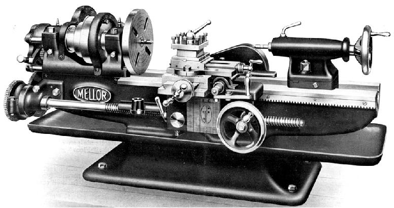
The Mellor lathe, on its cast-iron bench sub-base as advertised during WW2 in August, 1941. The twin bed feet, close together in the centre, can just be made out.
Continued:
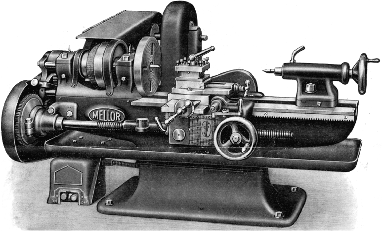
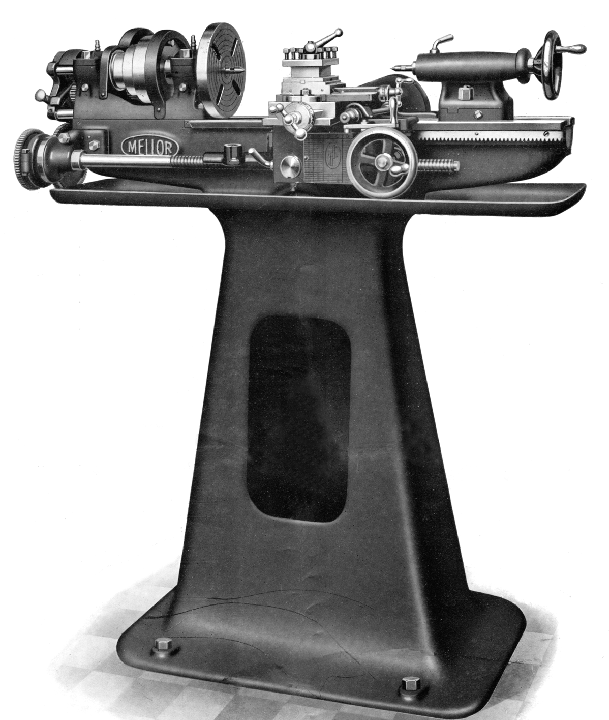
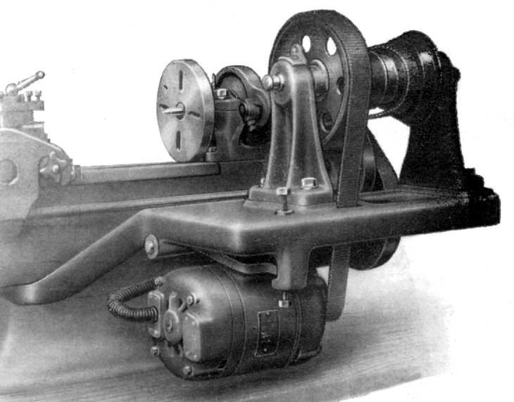
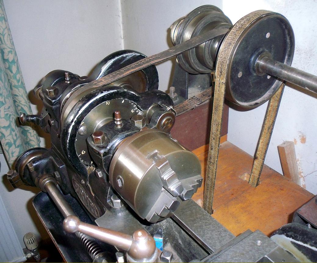
Two short feet, close together in the centre, supported the 6-inch wide, V-edged straight bed (no gap option was listed) and were bolted to either a low, cast-iron sub-base (with a heavy steel chip tray sandwiched between) for bench mounting (which would have accounted for some of the weight) or a very heavy "trumpet-style" floor stand. When mounted on the latter the total weight rose to 520 lbs and earlier models must have been even heavier still for, on those, positioned between stand and lathe was a thick cast-iron plate that carried a massive countershaft (with free-running, self-aligning ball-bearing) and, slung beneath it, the electric motor. The countershaft mounting holes were slotted to permit belt adjustment and also allow the rather clumsy but very comprehensive belt and backgear guarding to be aligned. Later models (as illustrated below) were, thankfully, simplified and used a more conventional arrangement with the countershaft fastened to the back of the lathe bed or supplied with a separate countershaft, two hangers (with double-row bearings) and a suitable belt-shifter.
Bored through 13/16", the No. 2 Morse taper ground-steel spindle was ran in bronze bearing each 21/2" long with the front 13/8-inches in diameter and the rear 13/16". Although of the simple, split-parallel type the bearings were, for the size of the lathe, of generous dimensions and provided (at least on some versions) with spring-loaded wick-feed oilers which drew their supply from large reservoirs built into the front of each bearing housing; a thoughtful touch was to provide these reservoirs with drain plugs so that the compartments could be flushed out.
Driven by 1-inch wide flat belt, the spindle mounted a 3-step pulley the largest diameter of which was 5 inches and the smallest 21/2". The countershaft of later models of the fast-and-loose type, driven by a 1 3/8-inch wide belt and designed to run at 350 r.p.m. This gave a speed range, including the 6.25 : 1 ratio eccentrically-mounted backgear, of approximately 28 to 700 rpm. Although not mentioned as an option in the catalogue it is possible that some lathes were supplied with V-belt drive; several survive in such a form and the quality of engineering leaves no doubt that these were a factory job.
A particularly interesting feature of the lathe was the provision of power sliding and surfacing (of a design also seen on the English Pools "Major" lathe) that allowed the Acme-form 7/8-inch diameter-by-1/4-inch pitch (4 t.p.i.) leadscrew to be left for screwcutting duties only. The feeds were driven by the old-fashioned method - even by 1930s' standards - of arranging the changewheels to drive not only the overhung, front-mounted leadscrew but a long 3/4-inch diameter shaft (again, overhung) that ran along the back of the bed. The shaft was keyed along its full length and passed through a worm gear (concealed under a domed hinged cover) fastened to the back of the saddle. The "wheel" driven by the worm drove, in turn, a gear connected to the end of the cross-feed screw; the gear was loose on the shaft, but could be tightened into engagement - and the power cross feed activated - by turning a butterfly nut. Arranged by bringing the drive forwards over the top of the saddle to act on the gear normally used to traverse the carriage by hand, the feeds were engaged and disengaged instantaneously by a sliding dog clutch under the control of a handle pivoted from the front face of the apron. With the normal changewheels set up in a compounded train to give the finest possible feed rates sliding was at 0.008" per revolution of the spindle and cross feed at 0.003". However, the makers did offer a fine-feed gear (presumably something like a 12t output gear on the tumble reverse) that gave feeds rates 2/3 as fine.
When operated by hand the carriage drive passed through a double-reduction gear giving a fine-feed rate and much improved "feel" over the direct rack-and-pinion arrangement then common on so many smaller English lathes. A tumble-reverse mechanism was fitted, engaged through a quick-action spring-loaded locating plunger, that acted both on the leadscrew and the power-feeds "back shaft" as Mellor called it. A generous set of 23 changewheels (of 16 DP) were provided as standard - including a 127t metric translation gear. As the leadscrew was 4 t.p.i. the set of gears is likely to have included the following: 20t, 25t, 30t, 35t, 38t, 40t, 45t, 50t, 55t, 60t, 70t, 75t, 80t, 85t, 90t, 95t, When compounded together the changewheels were held together by pins 3/32" in diameter.
Equipped with micrometer dials on both cross and top slides, the compound slide rest was fitted as standard with a large 4-way toolpost in wrought steel. The cross slide carried engraved degree marks to set the swivel of the top slide which, being of the "precision" lathe type with exposed slideways, had a useful amount of travel.
A long cast-iron cover, extending from the left hand face of the apron, protected the leadscrew and, because it was robustly constructed, provided a mounting at its mid point for a thread-dial indicator. Unfortunately tailstock centre was only 1 Morse taper - a strange shortcoming in what was otherwise a carefully thought out and competently-engineered little machine tool.
Supplied as standard with the lathe (in addition to those items already mentioned) were: a travelling steady (the makers using a corruption of the American usage: "following steady rest" ), faceplate, catchplate and one box spanner (for the toolpost screws) and two open-ended spanners. The lathe was finished in black enamel with the bare metal surfaces described as: "highly polished".
A capstan version of the lathe was also manufactured and boasted a massive 6-station indexing head mounted on a standard carriage with a powered cross feed. A separate cut-off slide was fitted between the carriage and headstock and, with this removed, the lathe could, to some extent (because the capstan head was able to move across the bed) be used as an ordinary centre lathe. The headstock was fitted with an extra-wide, 2-step flat-belt drive pulley - obviously with the intention of speeding up metal-removal rates.
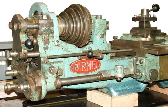
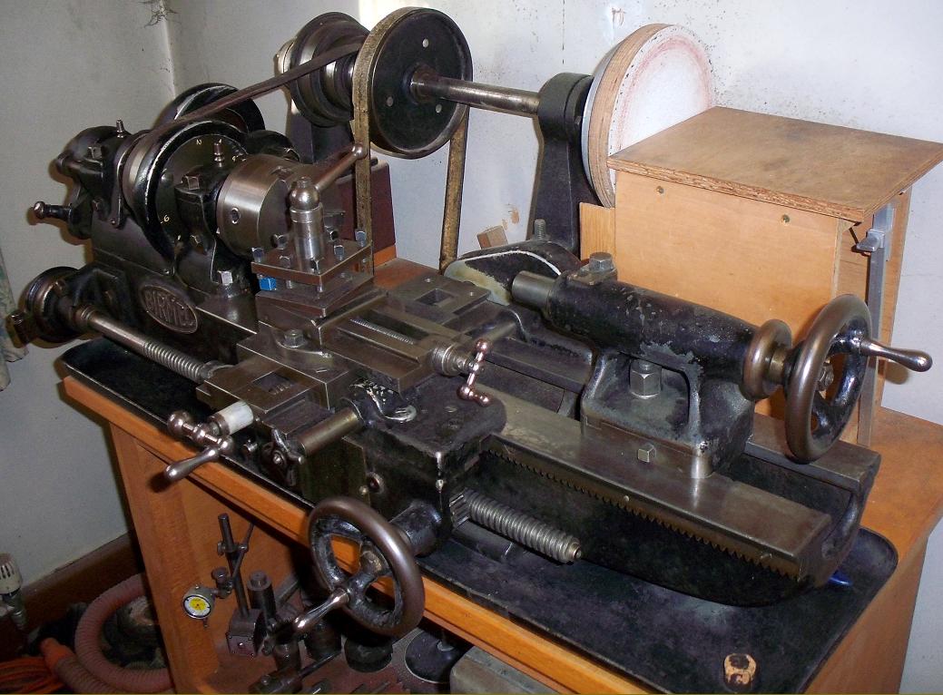
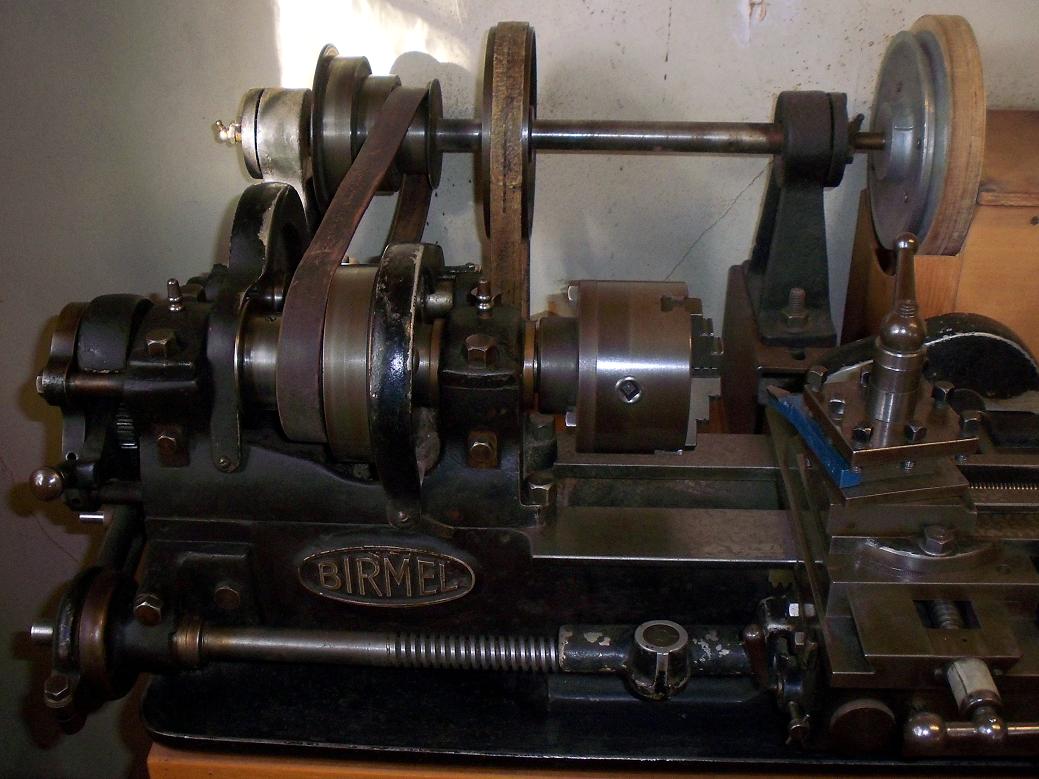
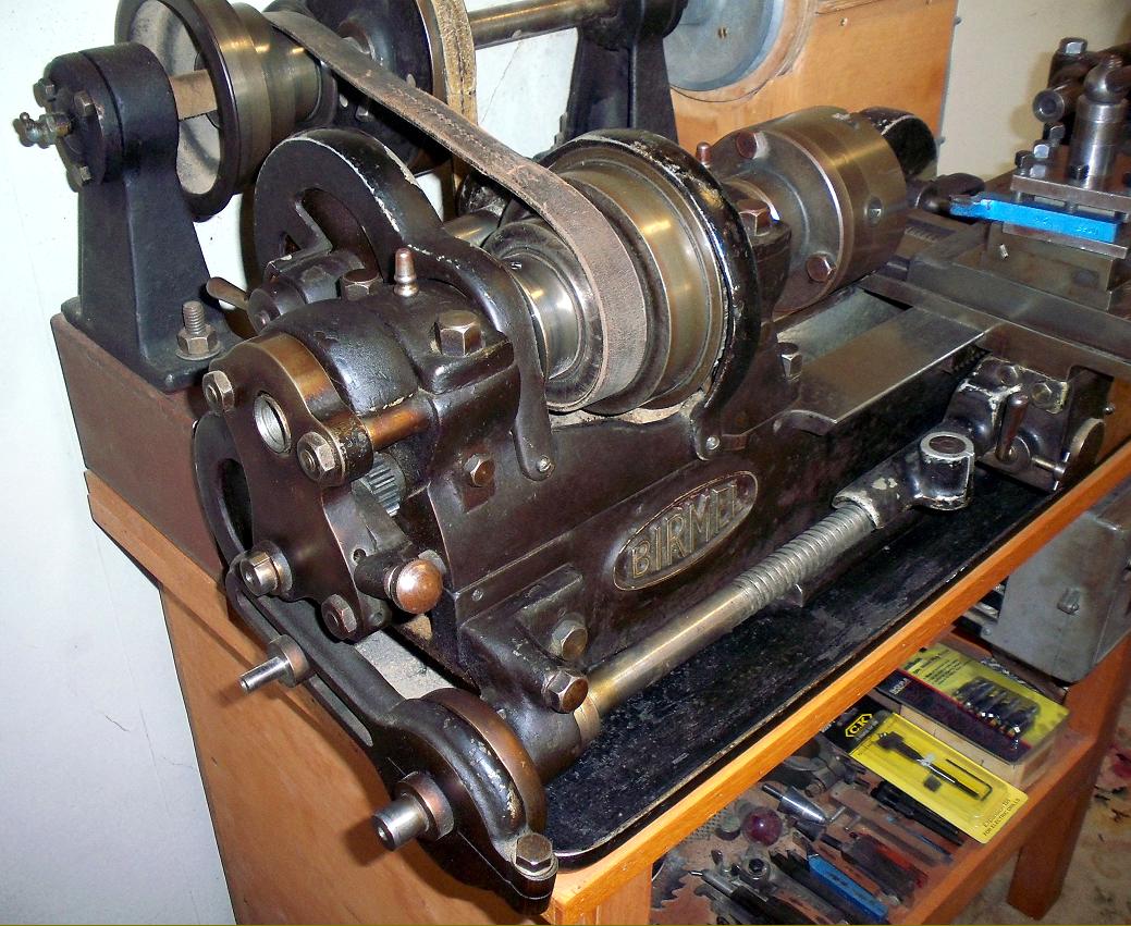
A considerable number of these machines are still about in the UK - six, for example, were known to be in factory use in the Redditch area as late as 2007. Some, during WW2, were bought by the Government and these were marked (hand painted on the stand) "War Finish". One interesting version of the Mellor A has been found badged as a "Birmel" and, while the background to this marketing exercise is unknown, this lathe exhibits some differences to the ordinary model, some being fitted with a cast-iron, 4-step "A" section V-belt drive headstock pulley and other with a flat belt. In addition, while the ordinary Mellor was somewhat limited by its No. 1 Morse taper headstock and tailstock centres, the Birmel was much better specified with, respectively, No. 3 and No. 2 Morse tapers - the headstock spindle must also have been larger, the spindle thread being 1.25" x 10 t.p.i. Butterfly-nut operated cone clutches were used to engage both longitudinal and cross feed with the rear power-feed shaft being equipped with a2-speed Bendix gearbox.
If you have a Mellor or Birmel, or any maker's literature (or can offer any insights into the company and its larger products), the writer would be pleased to hear from you.
Pictures continued here and here..
|
|