|
Continued:
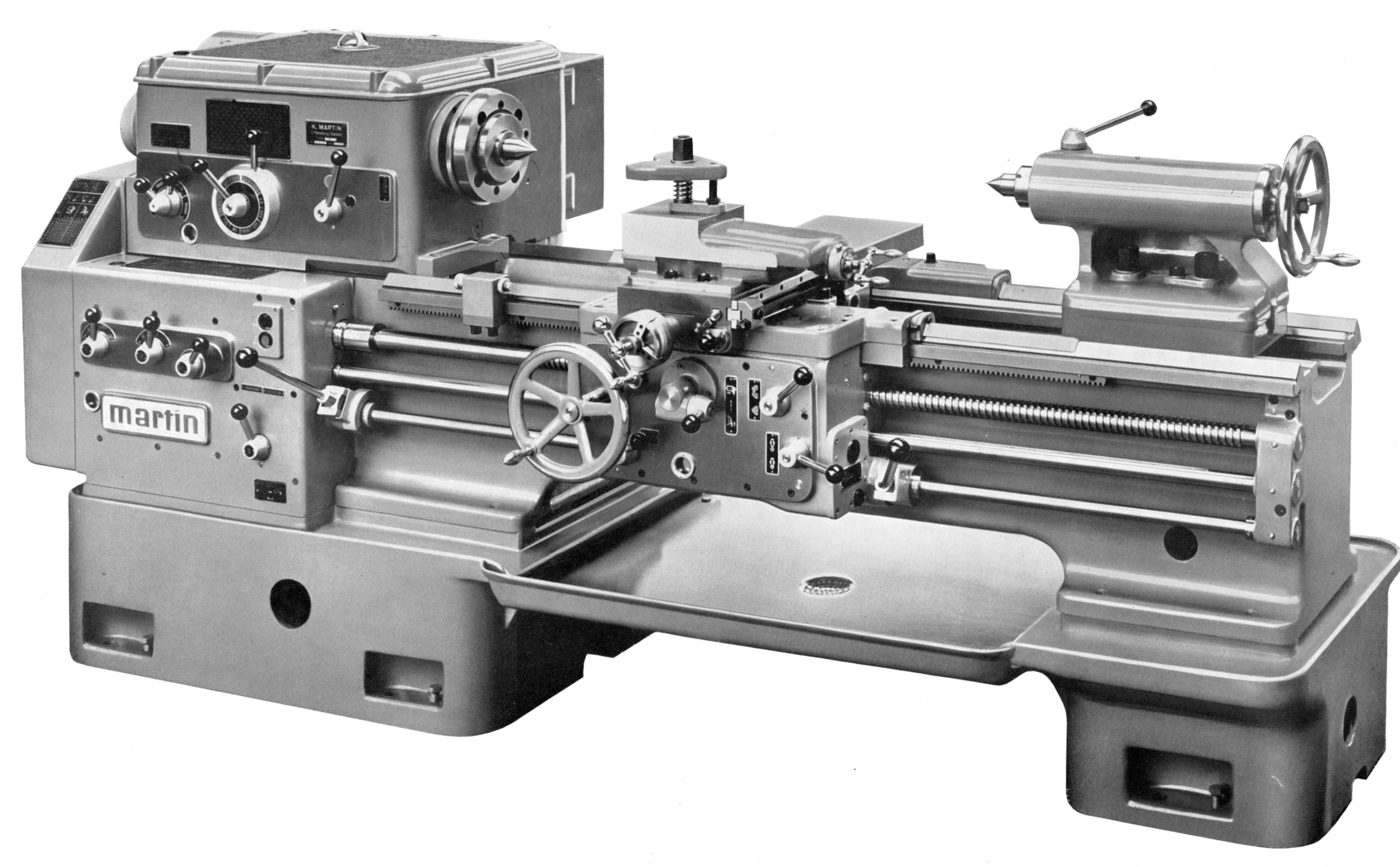
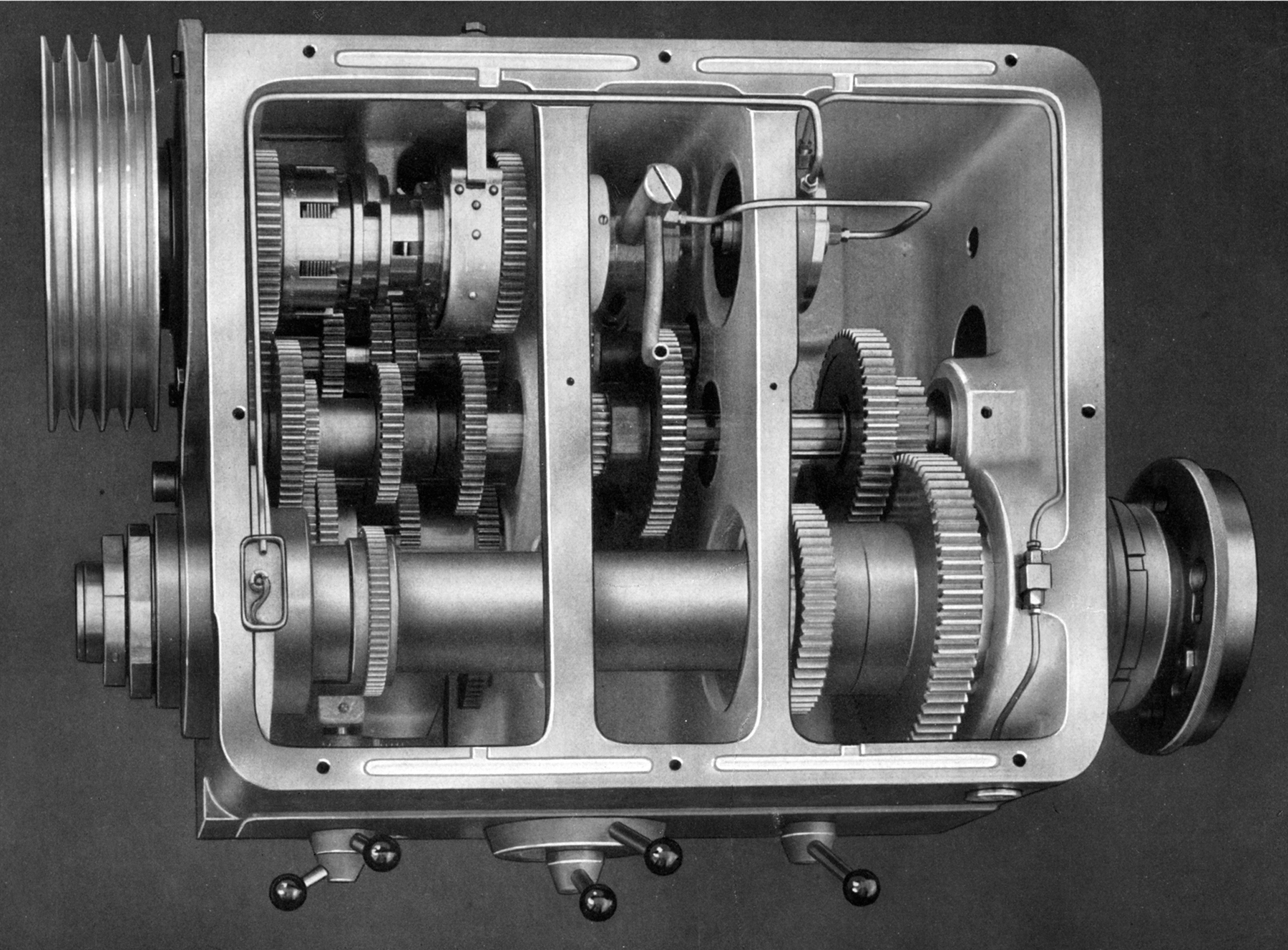
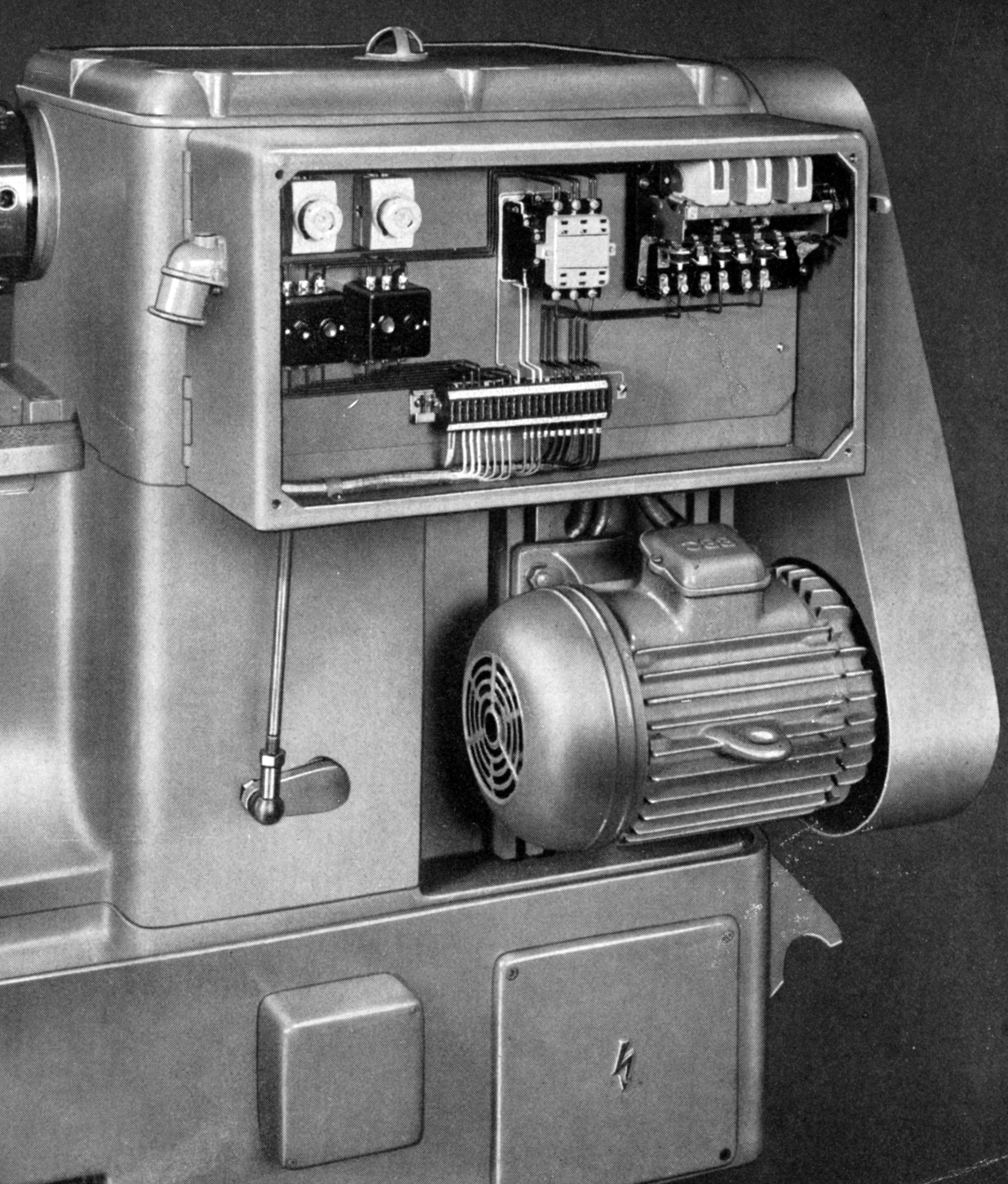
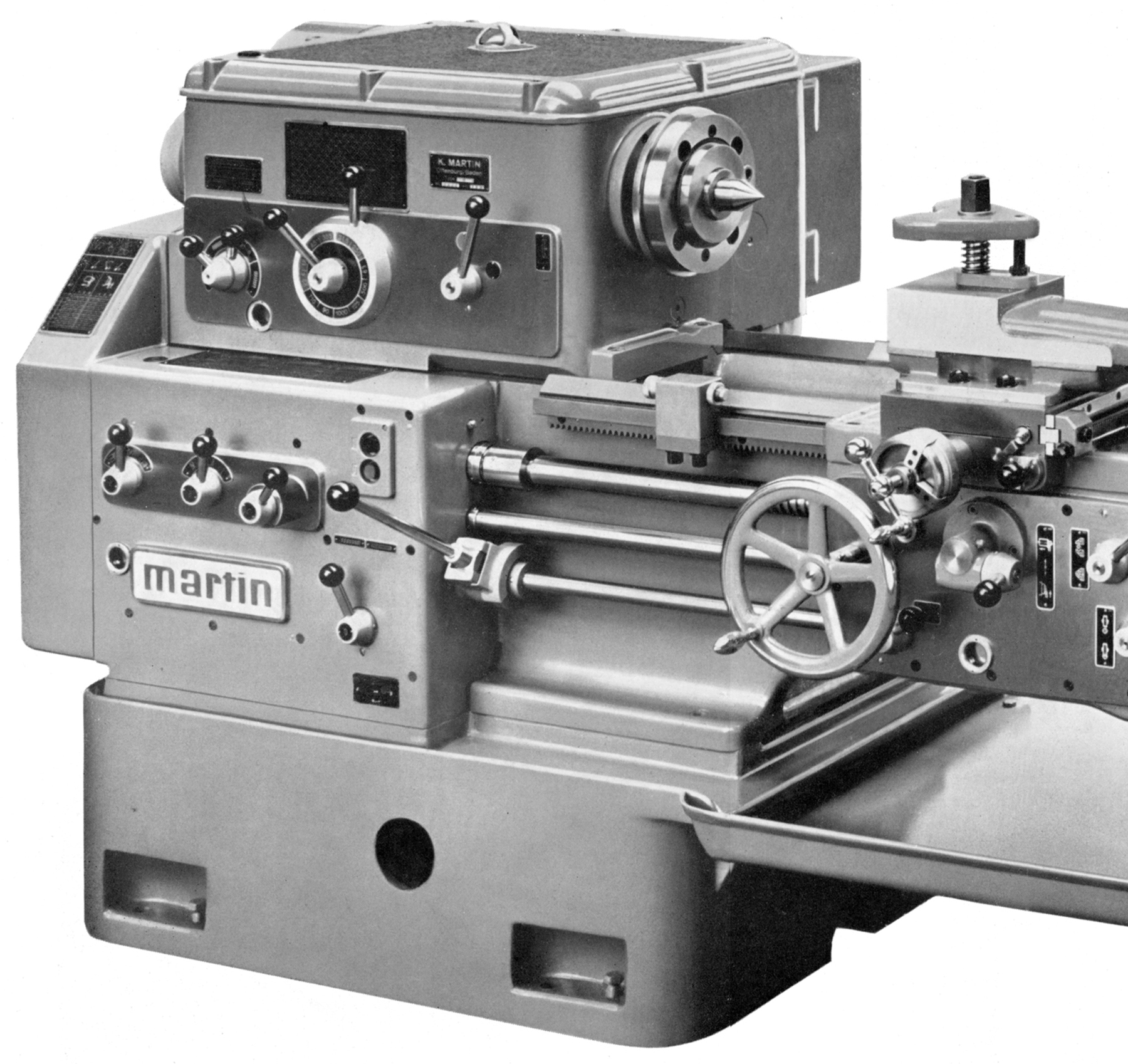
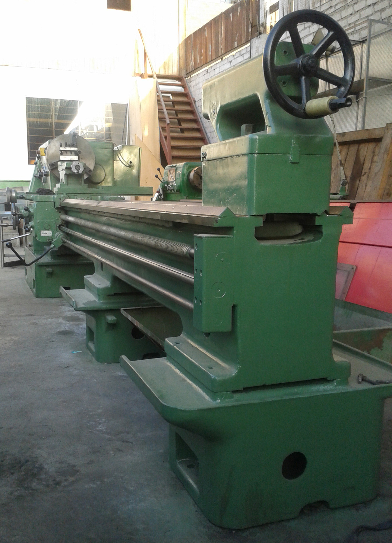
Drive to the headstock was by four B-section V-belts direct from a motor adjustable up and down to set the belt tension by being foot-mounted on a pair of vertically disposed rails bolted to the back of the headstock. The drive passed into the headstock through a multi-disc, forward and reverse clutch and a powerful, brake of the external-band type - the latter being applied automatically as the clutch was disengaged., Above the motor, sealed safely in its own compartment, was the electrical switchgear, this whole unit being hinged and so able to be swung aside to give access for adjustment to the brake unit. Once power was switched on, electrical control of the spindle start, stop, reverse and brake was by a long control-rod set below and parallel to the powershaft with duplicated control levers to the right of the gearbox and (to ensure it was always within safe reach of the operator) pivoting from the right-hand face of the apron.
Screwcutting and power feeds were generated from a completely enclosed gearbox with control by levers - there being no open sliding tumbler by which means dirt and swarf could be admitted. Changewheels for driving the gearbox were contained within their own compartment and included (for the UK market at least) a specially-marked "indexing wheel" to assist with the production of 2, 3, 4, 5 and 6-fold multi-start threads. Using the standard-fit 2 t.p.i. (or optionally 12 mm) pitch leadscrew, both a standard range of 32 English (Whitworth) pitches from 4 to 56 t.p.i. and 21 metric from 0.5 to 7 mm could be cut without in any way altering the changewheel drive - though the 32 diametral and 9 module required the changing of four gears. Especially coarse pitches, set at sixteen times the standard range, were also available, these being generated by gears within the headstock with single lever bringing them into engagement; pitches provided were: 32 English from 1/4 to 3.5 t.p.i., 32 metric from 8 to 112 mm, 31 module from 2 to 28 and 32 diametral from 1 to 14. The makers also offered other sets of changewheels, to a customer's particular requirements, when special pitches had to be generated.
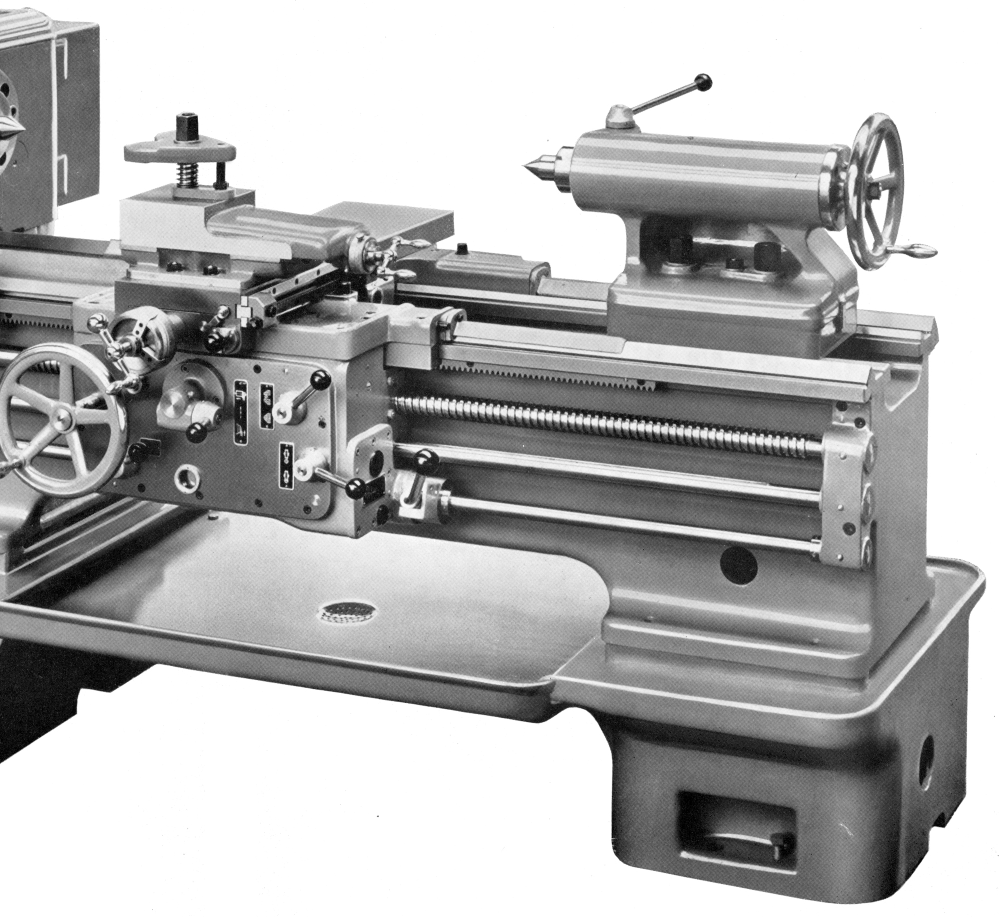
Power sliding and surfacing feeds driven from a separate feed rod comprised 32 of the former from 0.070 to 1.000 inches (0.070 to 1.000 mm) per revolution of the spindle and 32 of the latter at exactly twice as slow. At extra cost the makers could supply a fine feeds mechanism: sliding being 0.017 to 0.250 inches (0.006 to 0.0098 mm) per revolution of the spindle and, again, surfacing set to be twice as slow.
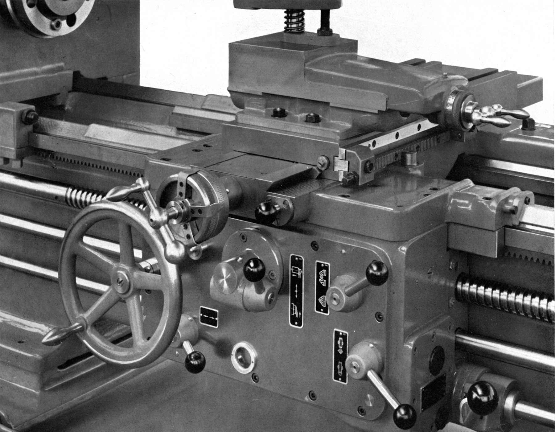
The compound slide rest was of substantial proportions with the cross slide (on UK-market models) of the full-length type two longitudinal T slots. The top slide could be swivelled 180° each side of central and fitted (for the size of lathe) with a rather prosaic triangular tool clamp - the aim being to persuade the new owner to specify something rather better. The "balanced" feed-screw handwheels appear to have been on the small size but, bearing in mind the care with which these lathes were assembled, and the smoothness with which they operated, this was almost certainly not a drawback. The cross-slide micrometer dial was fitted with three useful rotating radial spokes that allowed the turner to pre-set positions on repetition work. The bronze cross-feed nut was in two sections that allowed adjustments to be made to eliminate backlash.
Lubricated by an oil bath with a sight-glass to check the level, the double-wall apron was fitted with a drop worm for the engagement of the power sliding and surfacing feeds - this type of mechanism allowing an instant disengage even under the heaviest of cutting loads.
Standard equipment specified on machines for the UK market by the sole agents Stanton Machine Tools of Watford, was reasonably generous and included a complete electrical installation, a set of eight changewheels (5 mounted), a headstock reduction sleeve from 5 to 3 Morse taper, an extended cross slide, an ammeter, the fine-feed assembly, carriage longitudinal and cross-feed stops, two No. 5 Morse centres, the coarse screwcutting attachment, thread-dial indicator, grease gun, test certificate, operator's handbook and a set of spanners.
Extra equipment listed by the makers included: fixed and travelling steadies with roller-bearing or plain support arms, 12.5-inch catch plate, 20-inch faceplate, a 12-inch steel-bodied precision 3-jaw chuck, a 15-inch steel-bodied independent 4-jaw chuck (the steel-bodied chucks safe for the highest speeds), a 15-inch semi-steel independent 4-jaw chuck, complete coolant equipment, machine lighting with a 24-volt transformer, spare chuck backplates, 4-way and quick-set toolposts, single and double-holder rear toolposts and the appropriate parting-off tool holders to fit the extended cross slide, a longitudinal 4-position rotating carriage stop and a hydraulic copying attachment..
|
|