 |
|
|
|
|
|
|
|
|
|
|
|
|
|
|
|
|
|
|
|
|
|
|
|
|
|
|
|
|
|
|
|
|
|
|
|
|
|
|
|
|
|
|
|
|
|
|
|
|
|
|
|
|
|
|
|
|
|
|
|
|
|
|
|
|
|
|
|
|
|
|
|
|
|
|
|
|
|
|
|
|
|
|
|
|
|
|
|
|
|
|
|
|
|
|
|
|
|
|
|
|
|
|
|
|
|
 |
|
|
|
|
|
 |
|
|
|
|
|
 |
|
|
|
|
|
|
|
|
|
|
|
 |
|
|
|
|
|
|
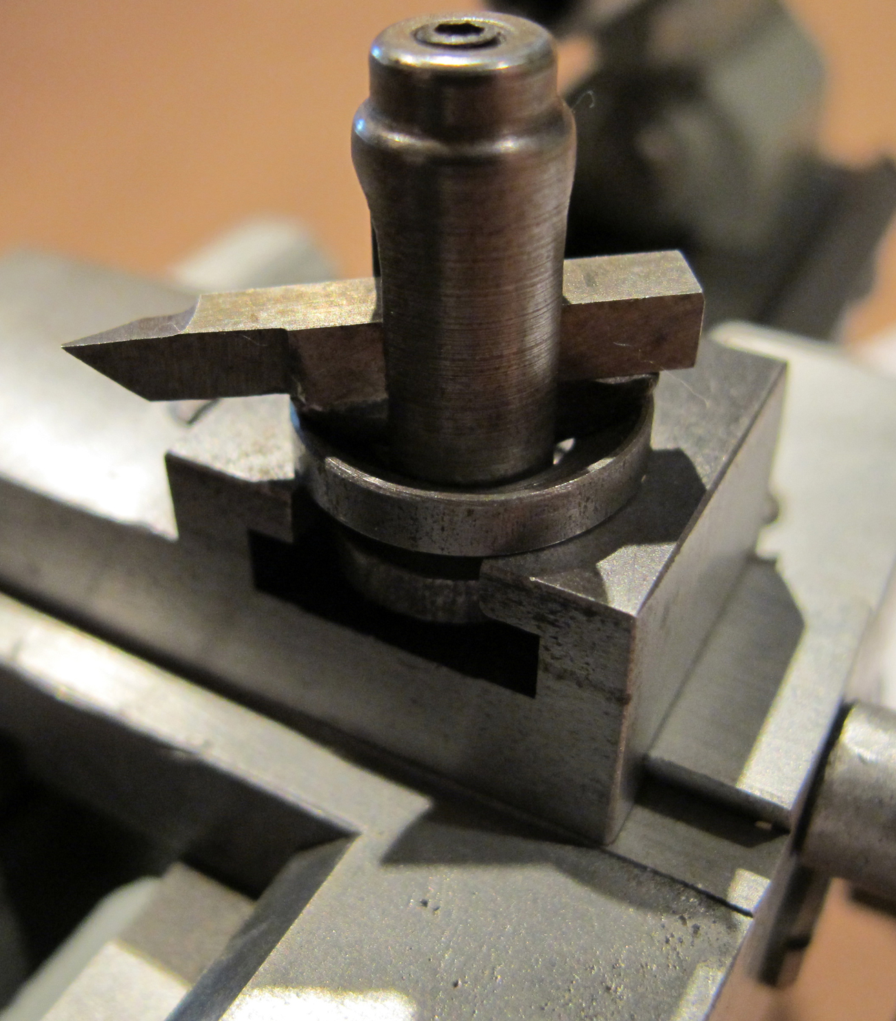
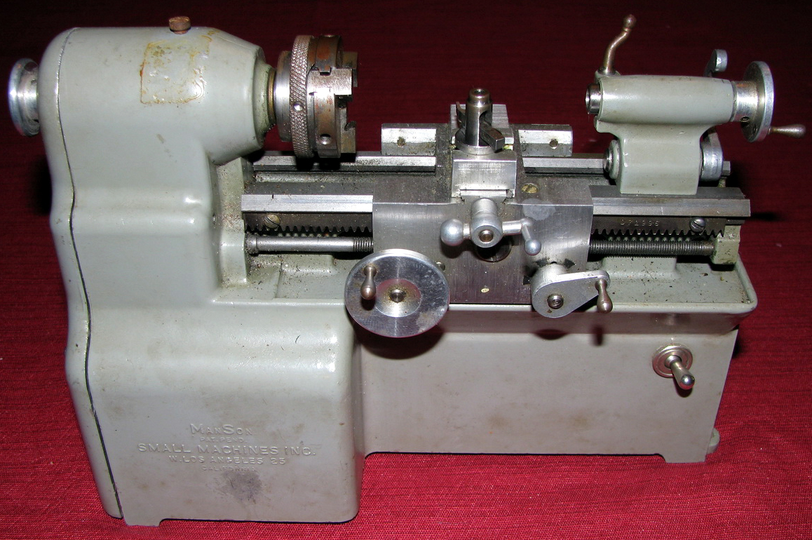
The toolpost was a miniature of the widely-used, quick-setting American "rocker type".
|
|
|
|
|
|
|
|
|
|
|
 |
|
|
|
|
|
|
Cross-slide casting, corrugated spring-steel self-adjusting gib strip and "American-style" rocker toolpost
|
|
|
|
|
|
|
|
|
|
|
 |
|
|
|
|
|
|
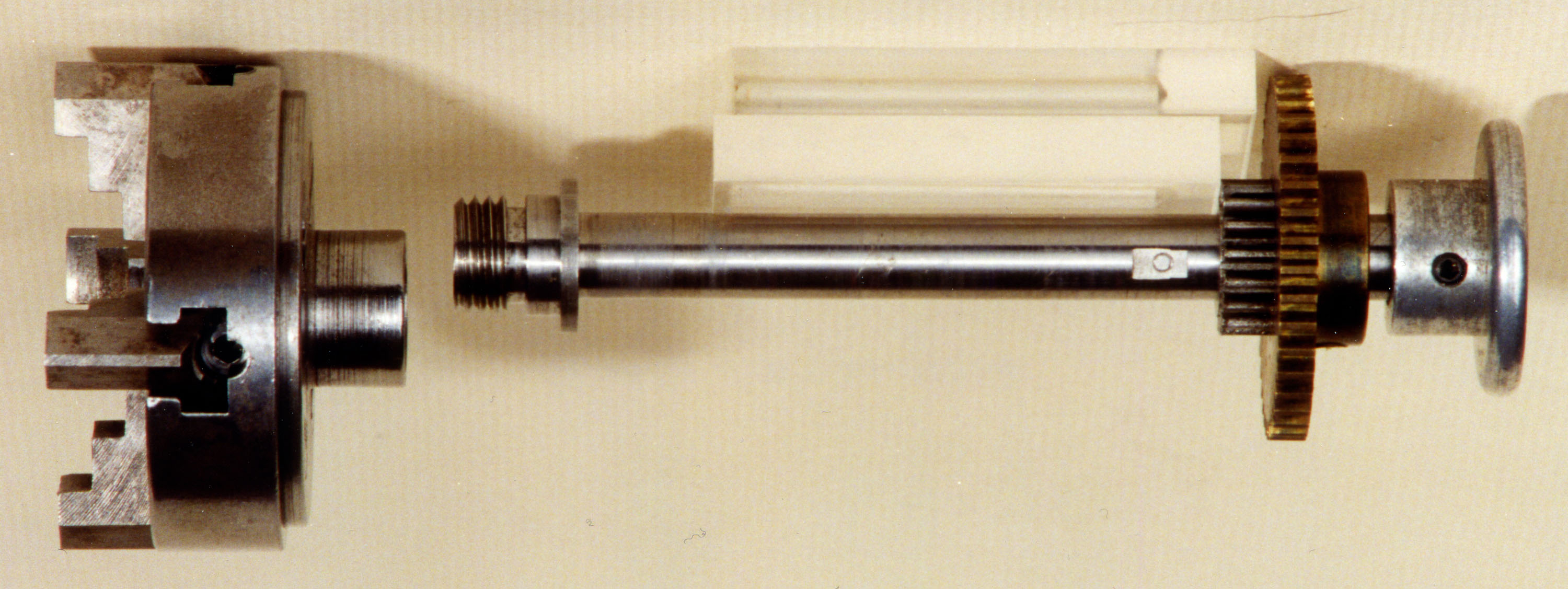
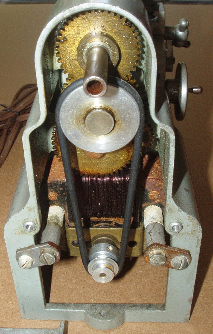
The complete spindle and gear drive assembly
|
|
|
|
|
|
|
|
|
|
|
 |
|
|
|
|
|
|
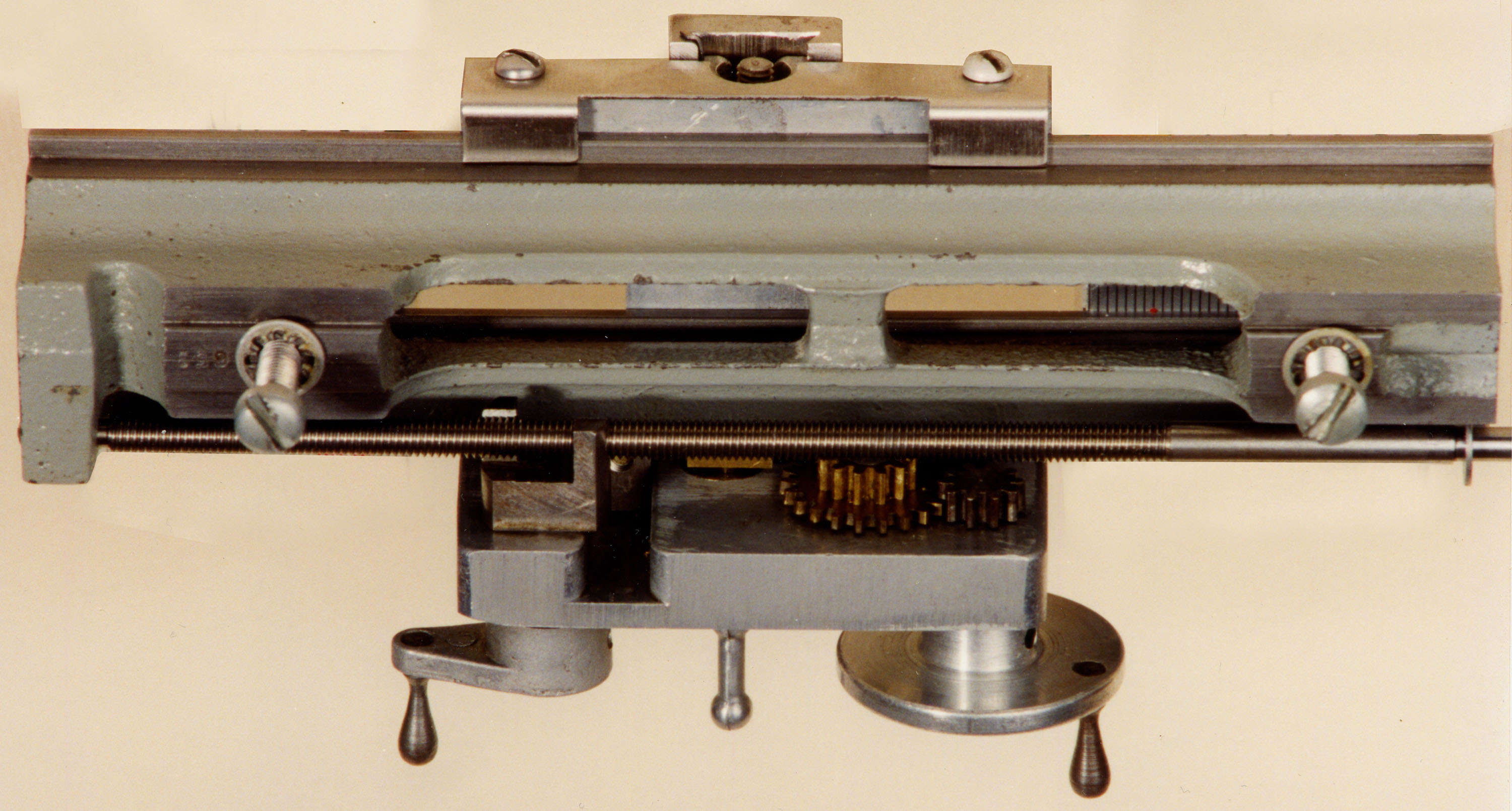
Under the bed - and back of the apron
|
|
|
|
|
|
|
|
|
|
|
|
|
|
|
|
|
 |
|
|
|
|
|
|
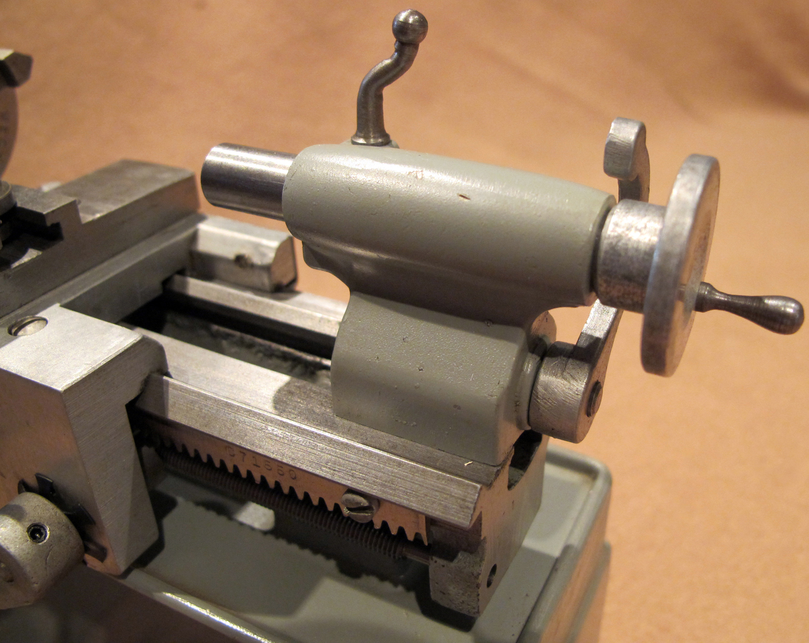
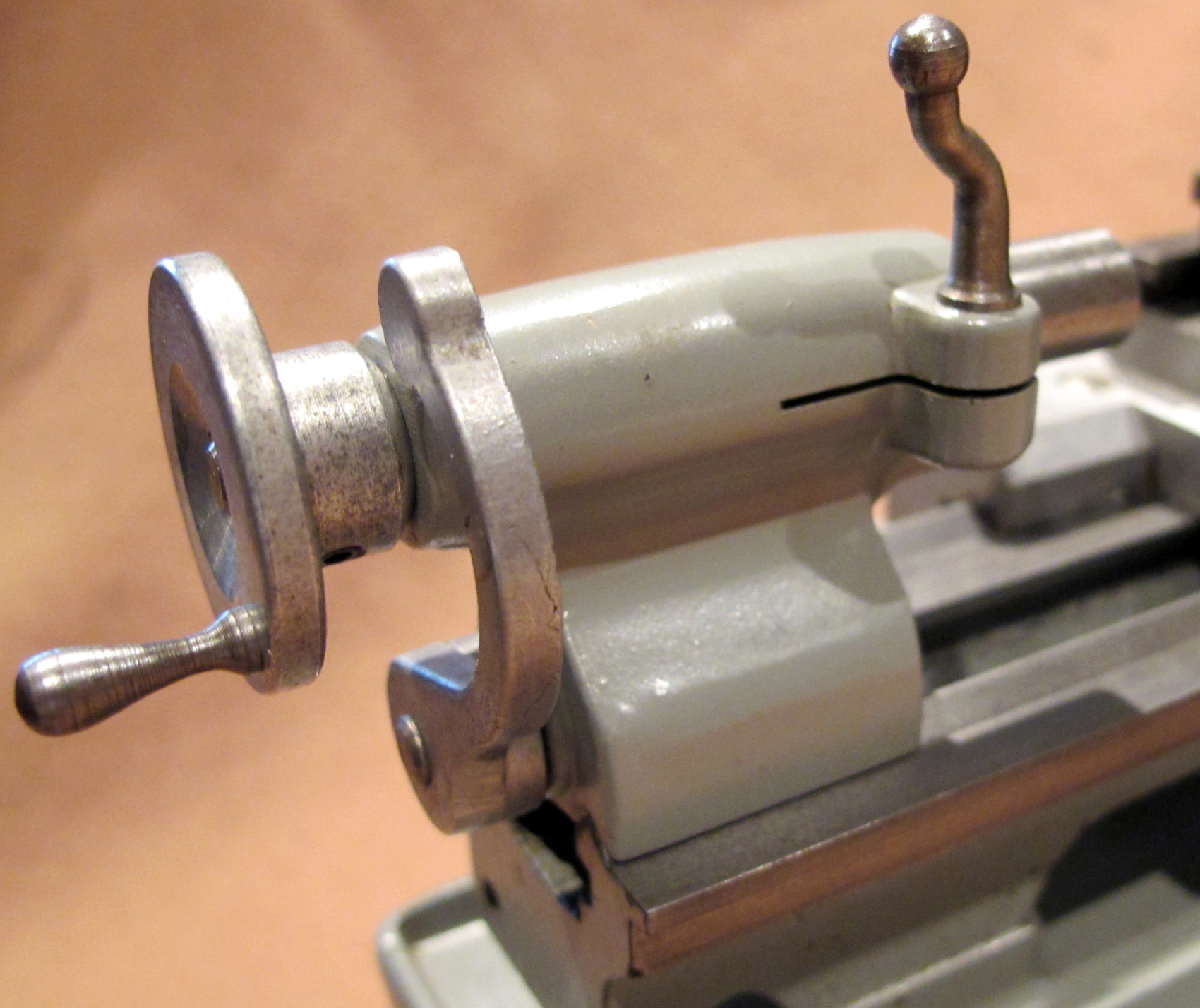
Looking as though it was carefully scaled from a very much larger lathe, the tailstock was locked to the bed by the action of an eccentric spindle running through the length of its base.
|
|
|
|
|
|
|
|
|
|
|
 |
|
|
|
|
|
|
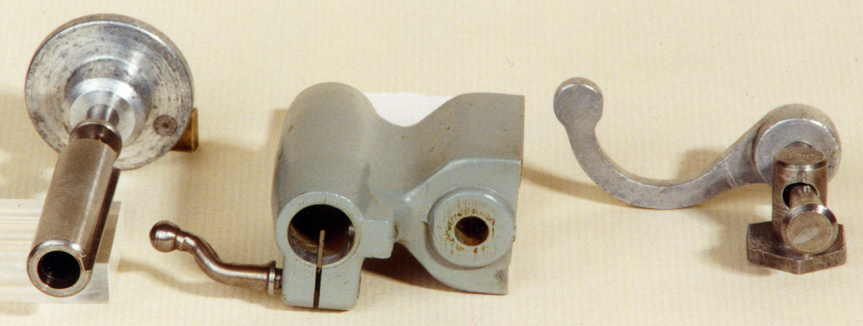
The barrel was clamped by closing up a slit in the casting.
|
|
|
|
|
|
|
|
|
|
|
 |
|
|
|
|
|
|
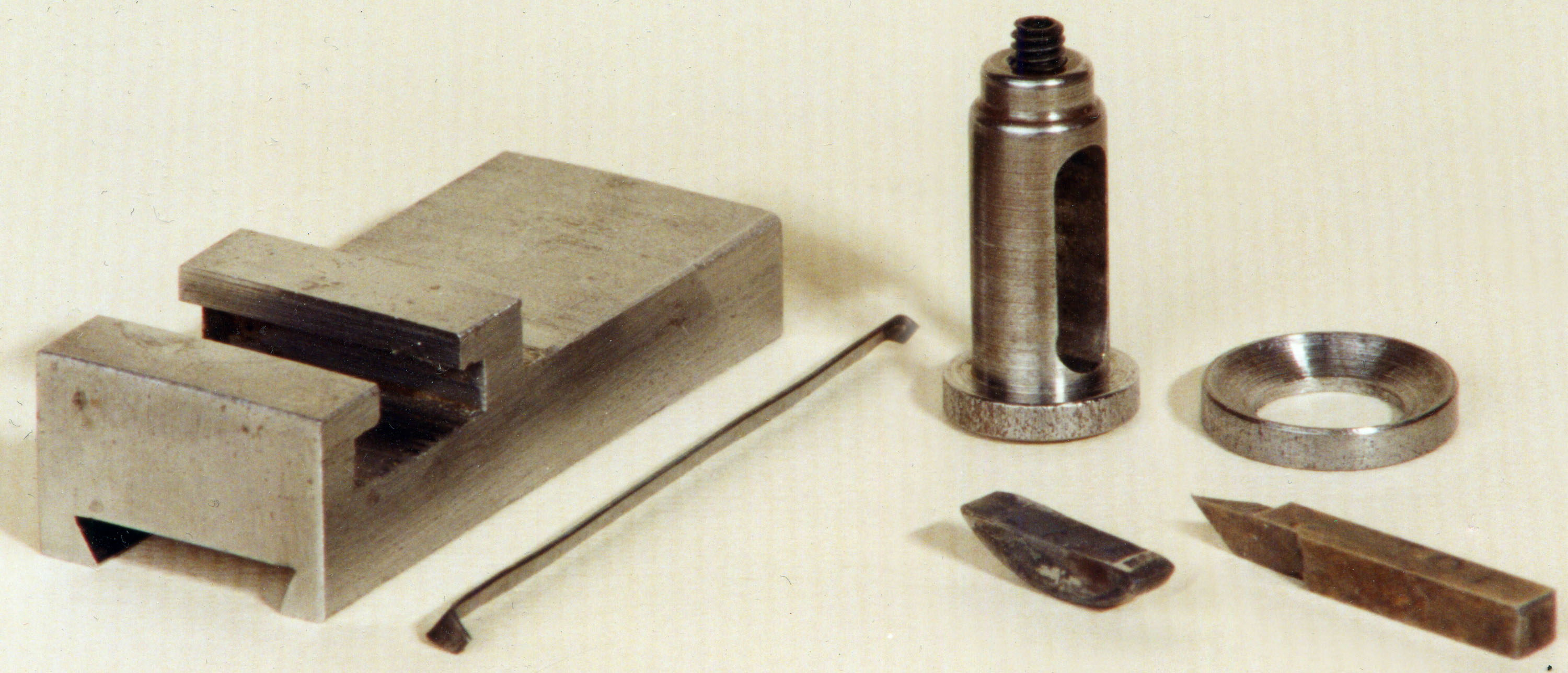
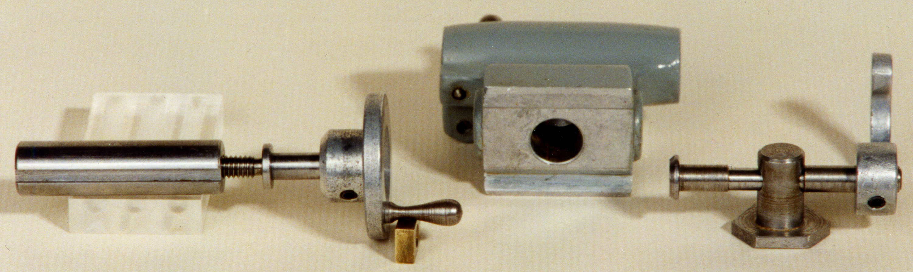
Above and below: a dismantled tailstock.
|
|
|
|
|
|
|
|
 |
|
|
|
|
|
|
|
|
|
|
|
 |
|
|
|
|
|
|
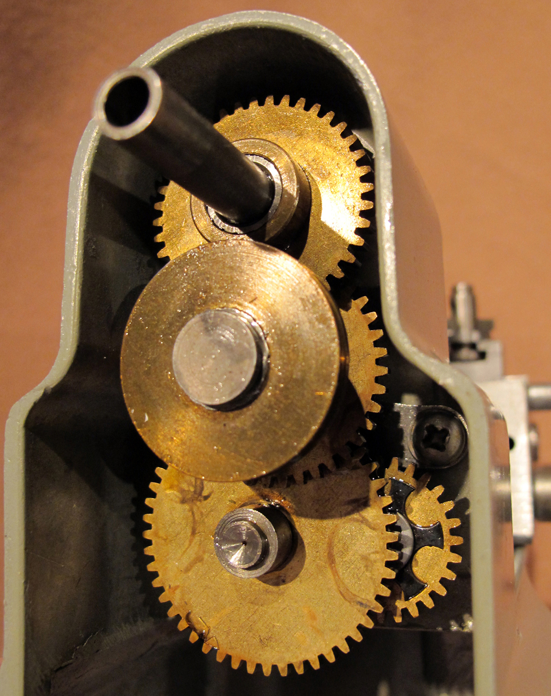
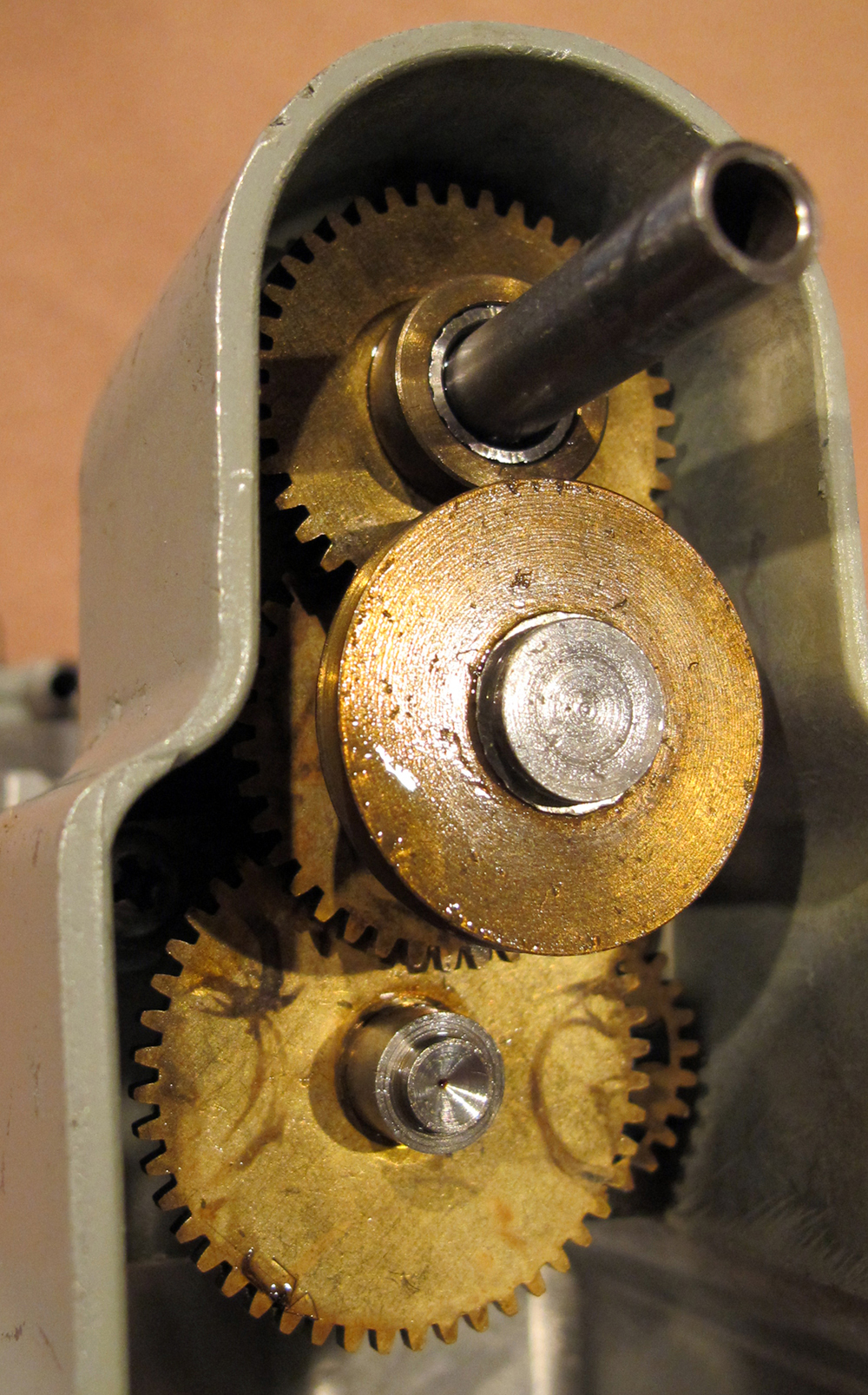
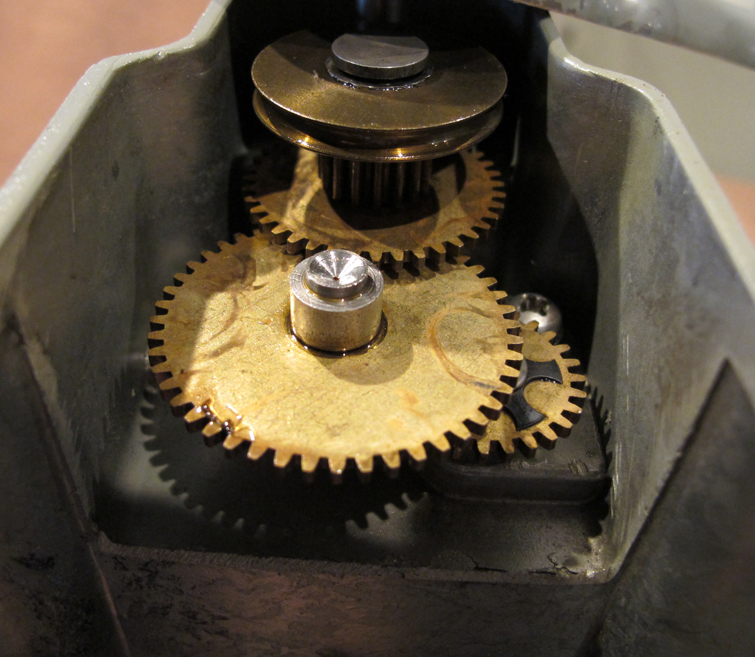
On the original ManSon the outboard drive pulley, with its rounded groove, was positioned below the spindle and carried three brass gears, one small independent - and an integral large/small pair. The small independent gear drove a larger gear, fastened to the headstock spindle and caused it to rotate. Inboard of the driven gear on the spindle was a much smaller gear, which drove back down to the large gear (of the large/small pair) mounted on the pulley shaft. The small gear of the pair then drove the larger gear of a large/small pair mounted below it - the smaller gear of the latter pair in turn drove another large/small pair - the smaller gear of which then drove a gear on the end of the leadscrew. In other words, a traditional compound-reduction gearing but contained within in a microscopic space and using gears of clock-like proportions.
|
|
|
|
|
|
|
|
|
|
|
 |
|
|
|
|
|
|
Clock-like brass changewheels of the original ManSon lathe
|
|
|
|
|
|
|
|
|
|
|
 |
|
|
|
|
|
|
|
|
|
|
|
 |
|
|
|
|
|
 |
|
|
|
|
|
 |
|
|
|
|
|
|
ManSon with evidence that the headstock bearing oil plug was held in place during transit by a length of sticky-backed tape. The ring-scroll 3-jaw chuck is an unusual fitting to find on a ManSon
|
|
|
|
|
|
|
|
 |
|
|
|
|
|
|
|
|
|
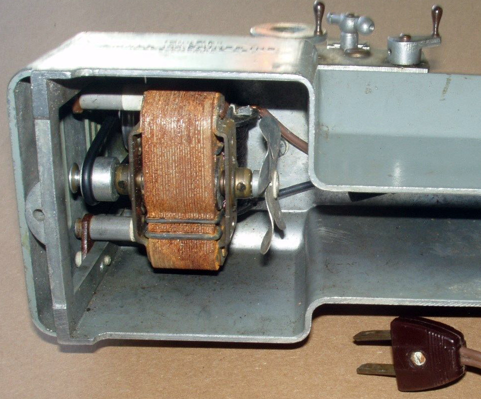
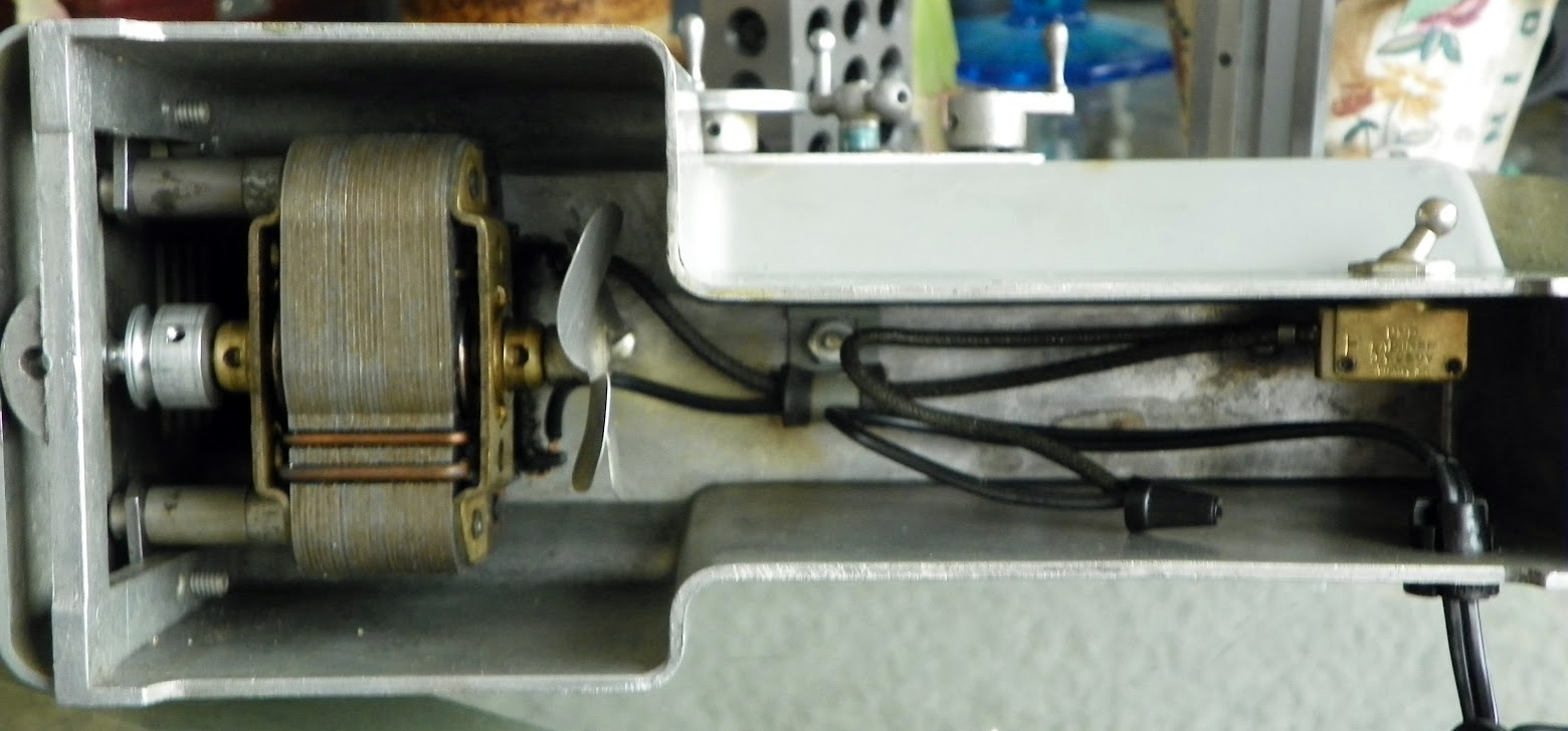
Another view of the first ManSon motor
|
|
|
|
|
|
|
|
|
|
|
|
|
|
|
|
 |
|
|
|
|
|
|
Crude, open-frame motor with exposed winding as fitted to the first ManSon lathes
|
|
|
|
|
|
|
|
 |
|
|
|
|
|
|
|
|
|
|
|