|
Home Machine Tool Archive Machine-tools for Sale & Wanted |
||
|
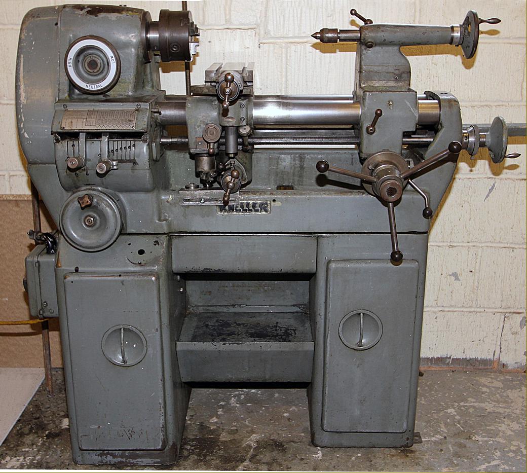
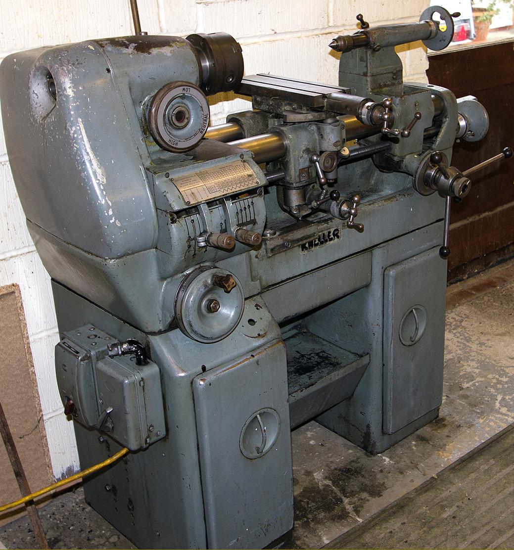
Developed from one of their earlier models, the Scope, the
Kneller 7.5" x 20" Combination Machine was made by Kneller Instrument & Tools Ltd. of Daventry a well-established
and very successful firm of precision engineers who did much sub-contract work for the aircraft industry including parts for the
Concorde prototypes and many jobs for Rolls Royce. In the form shown below, as the Type KPM Series
A, the Kneller was introduced to the British Market in 1964 through dealers Rudkin & Riley Ltd. of
Leicester. The lathe was of ingenious design, and very high quality, and as a result cost, in basic form, nearly £800 - or today's equivalent of about
£15,000. It was intended to be a multi-purpose unit, combining the normal facilities offered by a screwcutting centre lathe with the possibility of undertaking
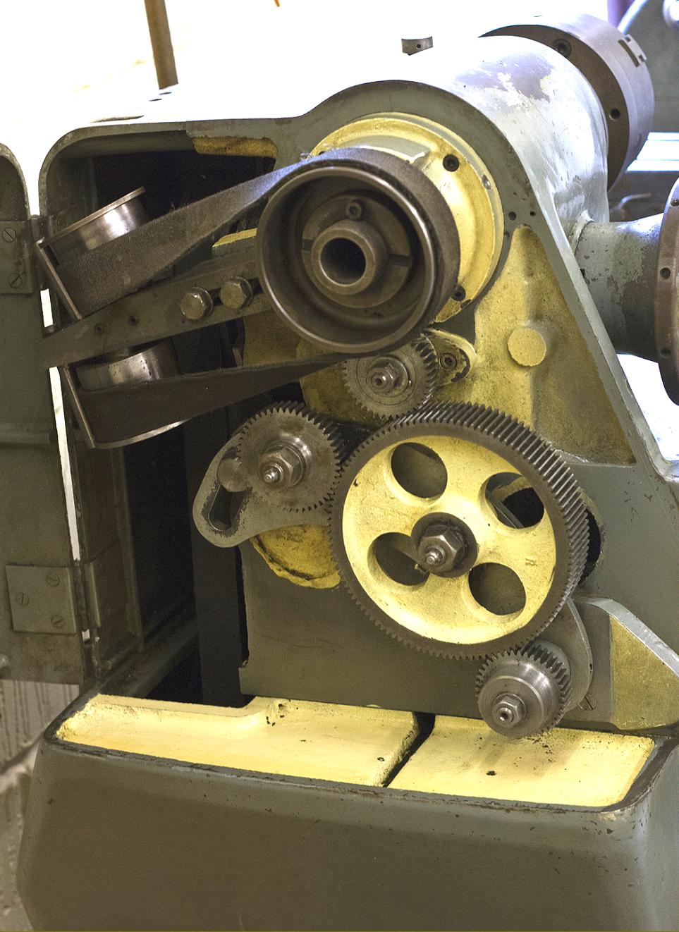
shaping, drilling, boring and milling - though it was not as versatile as such highly-developed but much more expensive machines such as the Meyer & Burger UW1 and Leinweber UW21. From conversations with visitors to the factory, it seems the lathes were built up in batches of twenty or so at a time with production equipment including a variety of first-class machine tools that included a number of Kneller lathes adapted for various special processes. The heart of machine was the bed, a pair of ground-finish hardened steel bars - socketed into alloy cast-iron housings at each end - that were so well made that the axis of the spindle in relation to them was held at a maximum error of 0.0005" per foot. Running in adjustable, pre-loaded Timken taper-roller bearings, the 1-inch bore, No. 4 Morse taper headstock spindle was powered through its backgeared speed range of 20 to 1200 rpm by a 1 h.p single or three-phase motor. Drive was via a stepless variable-speed drive unit mounted within the cabinet stand; this drive was a two-stage type with an expanding-and-contracting pulley on the motor driving one of another pair on an intermediate countershaft, the second stage drive being by the second expanding and coontracting pulley to a final one above it. However, the drive did not finish there for the last part to the spindle was unusual, being by a wide flat belt that ran around two guiding jockey pulleys that turned it through 90° before it wrapped around a pulley mounted overhung on the end of the spindle. The spindle-speed control wheel was positioned immediately below the screwcutting gearbox, with the electrical switches conveniently to hand below and to the right. Oil-sump-lubricated by splash, the twin-tumbler gearbox gave a range of pitches from 4 to 112 t.p.i. and longitudinal and traverse feeds from .002" to .012" - the drive being able to move either the "carriage" or the tailstock. Also fitted with a capstan handle and a very large micrometer dial, the tailstock assembly was more like a second carriage and intended to be used as a shaping or slotting machine--the cutting tool being held in the spindle. Fitted with the intention of being as versatile as possible, the 7" x 3.5" cross slide of the lathe had an enormously long travel, carried two T slots and was mounted on a large-diameter column that rose, under screw-feed control, from the centre of the saddle between the hardened and ground solid-bar bedways. A smaller "bracing" column steadied the slide at the front and the whole unit could be elevated through some 3.5", sufficient for the table to be used as a platform for horizontal boring and, with the optional facing head and worm-operated dividing unit, for drilling, tapping, boring, facing, thread cutting and milling. The slide was also arranged to swing around its central mounting column - 45 degrees clockwise and 20 degrees anticlockwise. By mounting the dividing head on top of the tailstock - which could be moved by hand from the capstan wheel or under power from the feed shaft - a further range of machining possibilities was opened up. Supplied with the lathe as standard was a compound slide rest, a thread-dial indicator, 10-inch diameter faceplate, 6-inch diameter facing and boring head unit - and a dividing unit (with the same nose fitting as the lathe spindle). Available as optional extras were: coolant equipment, fixed tool post, low voltage lighting, fixed and travelling steadies, chucks and Clarkson collet chucks for holding milling cutters. Although specifically constructed for its task, and beautifully made, the lathe was so expensive that several independent machines could have been purchased for the same outlay - though if room were a problem, such as on a ship or in a specialist's workshop, it would have made good sense. It is doubtful if large numbers were sold in the UK, the writer for example only ever having encountered a handful, all of which were owned by skilled, experienced engineers involved in producing complex, difficult-to-machine components. Occupying a space five feet long by two and a half feet deep the Kneller weighed half a ton The illustrations below give some indication of the jobs the machine could undertake. If you have a Kneller, the writer would be very interested to hear from you. Pictures continued on Page 2 |
|
|
|
|
||
|
backwards and employed as the ram of a shaping machine |
||
|
Boring machine using the standard 6-inch facing and boring head. The job on the table was machined completely on the lathe including the internal thread cut using the boring head with the saddle travelling at the thread pitch rate. |
||
|
|
||
|
Home Machine Tool Archive Machine-tools for Sale & Wanted |
||