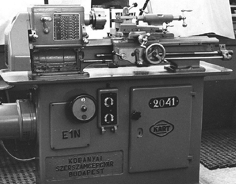
Karat & Kart Lathes
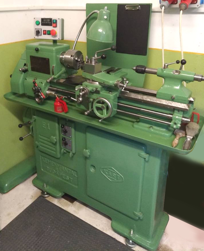
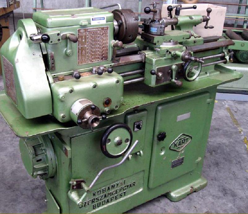
Manufactured by "Kobányai Szerszámgépgyár" Budapest, "Karat" lathes were imported by the Frye Machine Tool Company of Slough. However, to keep the origin a secret, Frye printed only "anonymous" sales catalogues with no indication as to the origin of the machines. "Kobánya" is a district of Budapest with the suffix "i" (Kobányai) meaning something like "from Kobánya" or "located at Kobánya"; "Szerszámgépgyár" for "Machine tool factory"; "Szerszám" for "tool"; "gép" for "machine" and "gyár" meaning "factory".
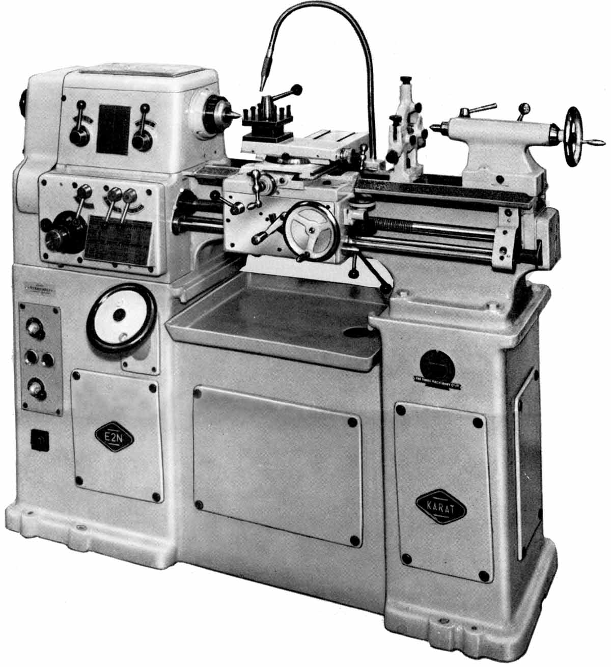
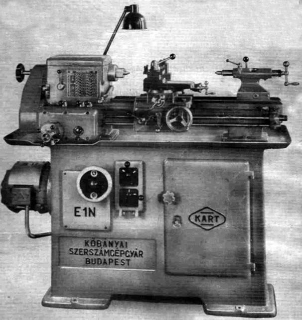
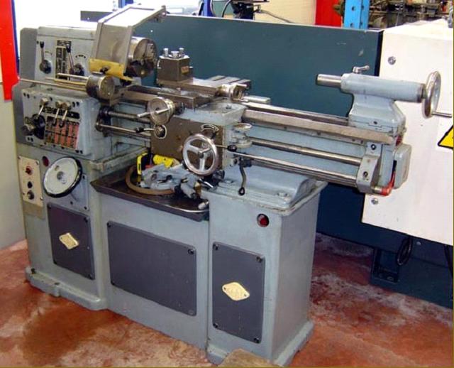
A popular model, or at least the one most heavily promoted, was the "E2N Precision Toolmakers". This was manufactured from the early 1950s until the 1970s with the first versions having the rounded styling of the era and then, from the early 1960s, with a more modern, angular appearance. A smaller model, the E1N, was also marketed and also appears to have sold well.
Although of modest size, with a centre height of 5.25-inches and a capacity between centres of twenty or thirty inches, the E2N was carefully designed and properly constructed weighing 1253 lbs and 1436 lbs respectively for the 20 and 30-inch versions It also included design features usually found only on much larger lathes and was fitted with a motor powerful enough to enable the toughest of jobs to be completed with ease.
Cast integrally with a large box at the headstock end (that contained the screwcutting and feeds gearbox) the 7.5-inch wide bed also had an unusually large foot under the tailstock end. The ways were V and flat with that at the front having a steeper angle on the inside, to better absorb thrust, and a wide shallow-angled section on the outside designed to give wider support the saddle and the chance of an extended life before wear began to affect accuracy. The bed was mounted on a very heavy cast-iron stand, with levelling screws at each corner, a slide-out chip tray and the electrical equipment - motor overload units, light transformer, signalling lamp, contactors and fuses - neatly clustered together in the left-hand end compartment. Coolant equipment was fitted as standard with the receiving tank, 1/6 h.p. 2900 r.p.m. motor and gear pump held in the section between headstock and tailstock plinths.
Providing high and low-speed ranges, headstock gears were all hardened and ground and the 1.09-inch bore spindle ran in a large adjustable bronze bearing at the front and, to allow for expansion at operating temperatures, a pair of ball bearings at the rear. Lubrication was simple - by splash from a sump in the base of the casting.
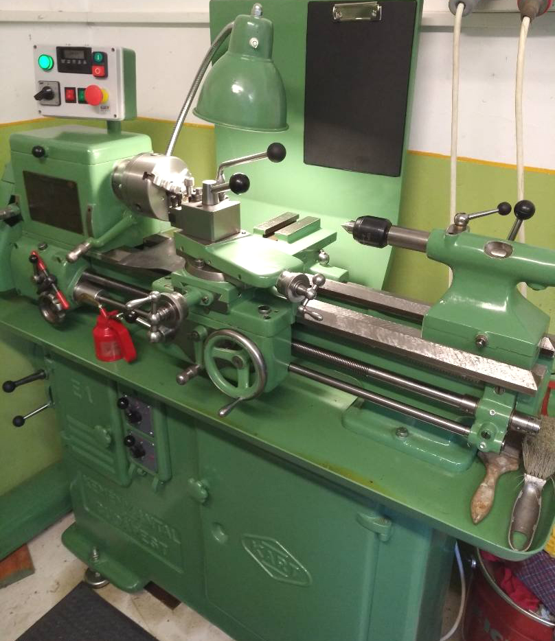
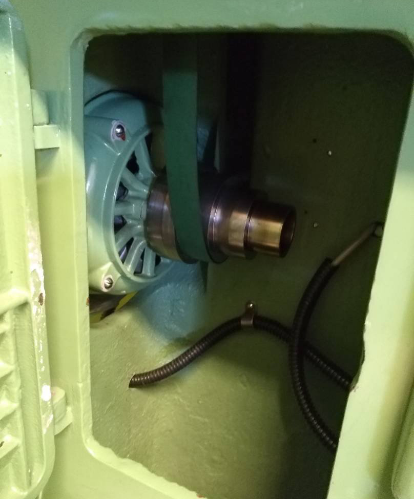
Fitted with an overhung 2-step V pulley, on its left-hand end, the spindle was driven from a 1450 r.p.m. 3-h.p. motor connected to an oil-immersed gearbox held in the bottom of the headstock support plinth. Electrical control of the motor was though a "third shaft" with the operating lever pivoting on and moving with the carriage. Twelve speeds were available, from 40 to 2160 r.p.m., controlled by a High/Low lever of the front face of the headstock and a large-diameter solid-disc wheel (positioned conveniently below the screwcutting gearbox) with a circular cut-out just inside the rim through which the speed reading showed. The general arrangement of the drive system (and many of its details) was remarkably similar to that used on the American Monarch 10EE and English CVA precision lathes.
Controlled by three levers and a rotary dial the screwcutting and feeds gearbox, was able to generate 52 metric, 32 inch and 44 module pitches and provided sliding feed rates from 0.0012 to 0.085 and cross feeds from 0.00024 to 0.017 - all in fractions of an inch per revolution of the spindle. An automatic knock-off mechanism was fitted allowing the carriage to be used with adjustable stops and long feeds left unattended.
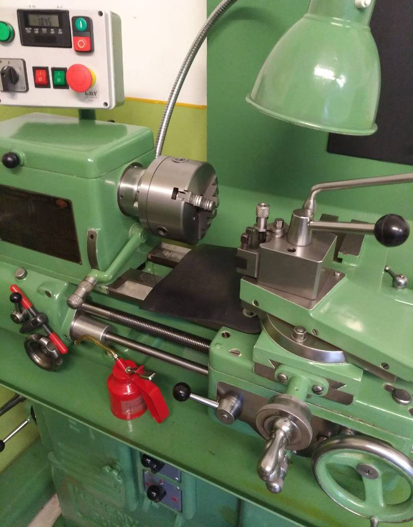
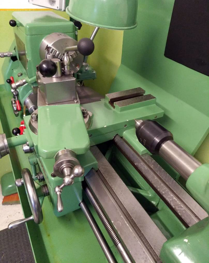
With a quadrant lever on its face to select neutral, sliding and surfacing feeds the double-wall apron was fitted with a useful, quick-action lever pivoting from the right-hand wall that allowed instant engagement and disengagement of the feeds. The compound slide rest was carried on the centre line of the saddle with the wide cross slide carrying a T slot along its right-hand edge and two more arranged in traverse behind the 360-degree swivelling top slide.
With a No. 2 Morse taper barrel, the tailstock could be offset on its soleplate for the cutting of shallow tapers. It was locked to the bed by a cam-action cross shaft and the barrel clamped by a proper two-part compression fitting working on a vertical axis.
Although a 3-jaw chuck was not supplied as standard, the equipment issued with the lathe was otherwise satisfactory: coolant, machine light, 10-inch faceplate, 5.25-inch backplate, fixed and travelling steadies, thread dial indicator (with an unusually large-diameter reading plate), 4-way toolpost and a screw-in collet draw-bar and 1/8", ¼", ½" and 5/8" collets - or their metric equivalents. If any reader has one of these now rare lathes, or any KART machine tool (a variety of types was made), the writer would be interested to hear from you..