|
Home Machine Tool Archive Machine-tools Sale & Wanted |
||
|
Yet another small English lathe, made from the early 1920 to the early 1950s, the 3.75" x 14" backgeared and screwcutting Ideal was manufactured by the Ideal Machine & Tool Co, London E8 but often badged and advertised by J. Willimott and Sons, Engineers, of Canal Street Works, Chilwell, Nottinghamshire, as their own product. Further addresses for Willimott were Neville's Factory, Chilwell, Nottingham during the 1920s and Hallam Road, Beeston, Nottinghamshire in the 1940s. The lathes were also advertised by Buck & Ryan (a well-known national tool and machinery supplier) as the "Faircut" - though the machine obviously had nothing to do with the Sheffield-based company whose lathes were of an entirely different design and far better quality (though might have been marketed by them). The Ideal was also to be found, along with many other "badge-engineered" lathes, in some pre-war editions of the Tyzack & Son machinery mail-order catalogue. Willimot also advertised milling machines, but none have yet been found (if you have one, the writer would be interested to know). Sales literature for all Willimot products is rare, and little is known of the lathes' official specification; however, both a lighter 3-inch version was made (backgeared and screwcutting with 12 inches between centres, a full nut on the leadscrew and fitted with a 3-step headstock pulley to take a round rope drive) and a heavier 3.5" x 18" model with flat-belt drive - a model that, judging by the numbers surviving, was very popular. The 3.5" was to be listed (by Willimot) under various designations including the Type A when fully equipped with leadscrew clasp nuts, rack drive for the carriage, backgear and compound slide rest. The Type B sacrificed the split nut and rack drive being fitted with a full nut on the dog-clutch-engaged leadscrew instead. A further Type, the B2, was also listed - but this differed only in being fitted with a single swivelling tool slide in place of a proper compound unit. Although the basic 3-inch lathe was reasonably priced at £7 : 18s : 6d, the larger model was expensive being, in 1929, listed at £19 : 15s ; 0d for the Model A, £18 ; 15S ; 0d for the B and £18 : 0s :d for the B2. An "Acme" version was also listed, with two models available, the A and A1, though what differences existed between the two is not known. |
|
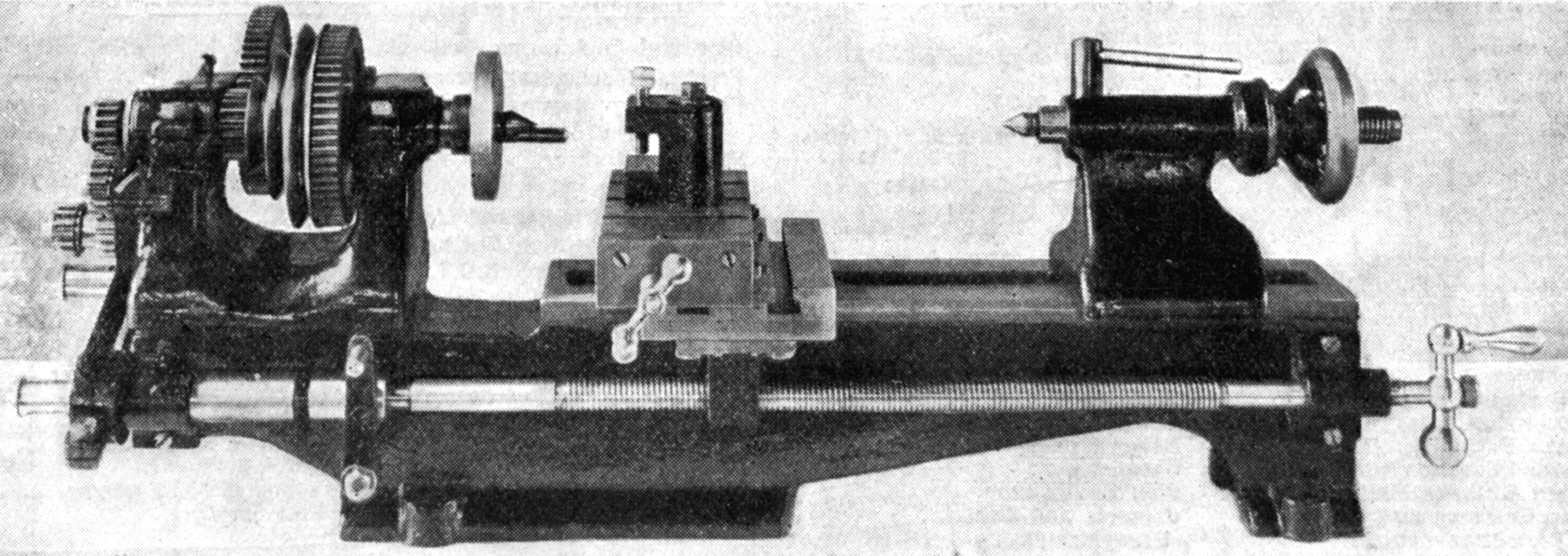
The rare 3-inch Ideal as it appeared in a publicity picture during the 1920s. Backgeared and screwcutting with a dog clutch on the leadscrew (and possibly fitted with tumble reverse), it was offered at £7 :18 : 6d, with a compound slide rest extra |
|
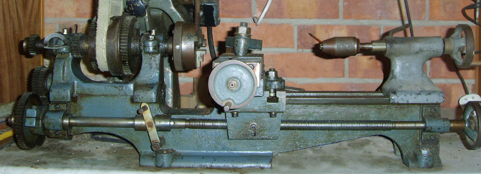
One of only a few surviving Ideal 3-inch lathes - but almost certainly of a different era to the one shown in the publicity picture. A number of differences are evident including: a simplified tailstock, flat belt instead of round-rope drive to the headstock pulley and the handles fitted to the leadscrew end and cross slide similar to those used on the later and larger models branded as "Ideal" |
|
An early 3.5" Ideal with flat-belt drive, a lightweight apron - cut away under the carriage hand-traverse wheel - and plain-bush split-type headstock bearings. While the latter were easy to adjust they were even easier to over-tighten and snap the casting. |
||
|
|
||
|
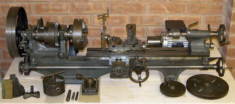
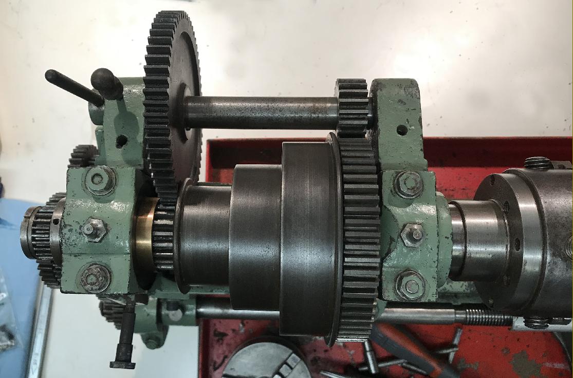
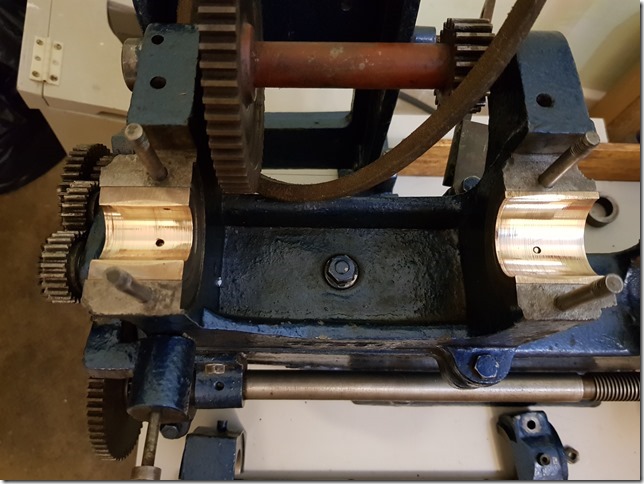
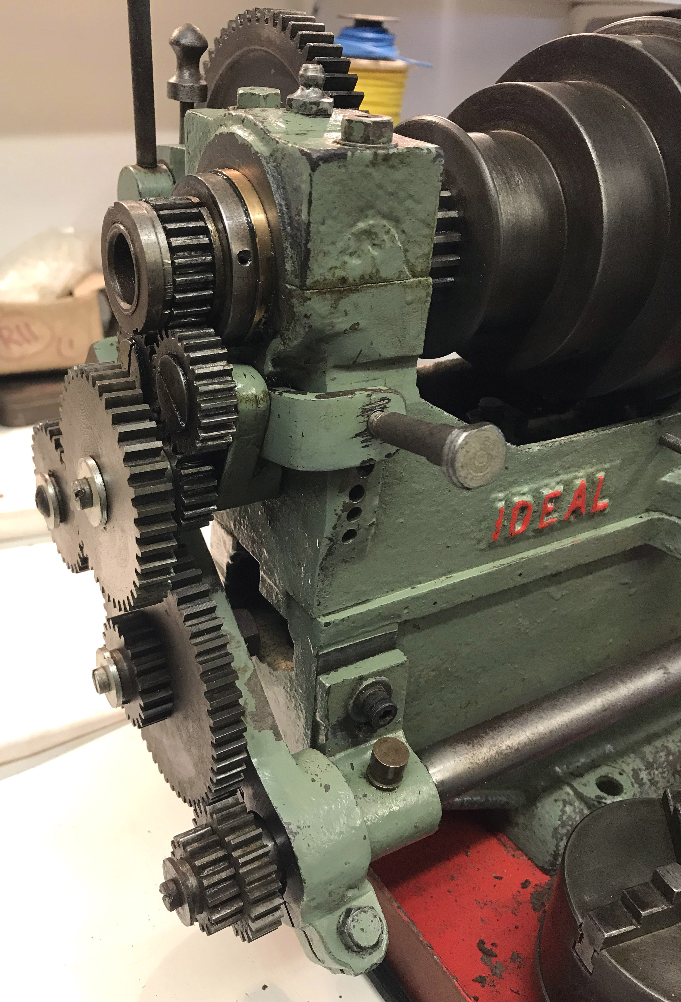
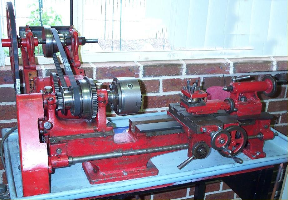
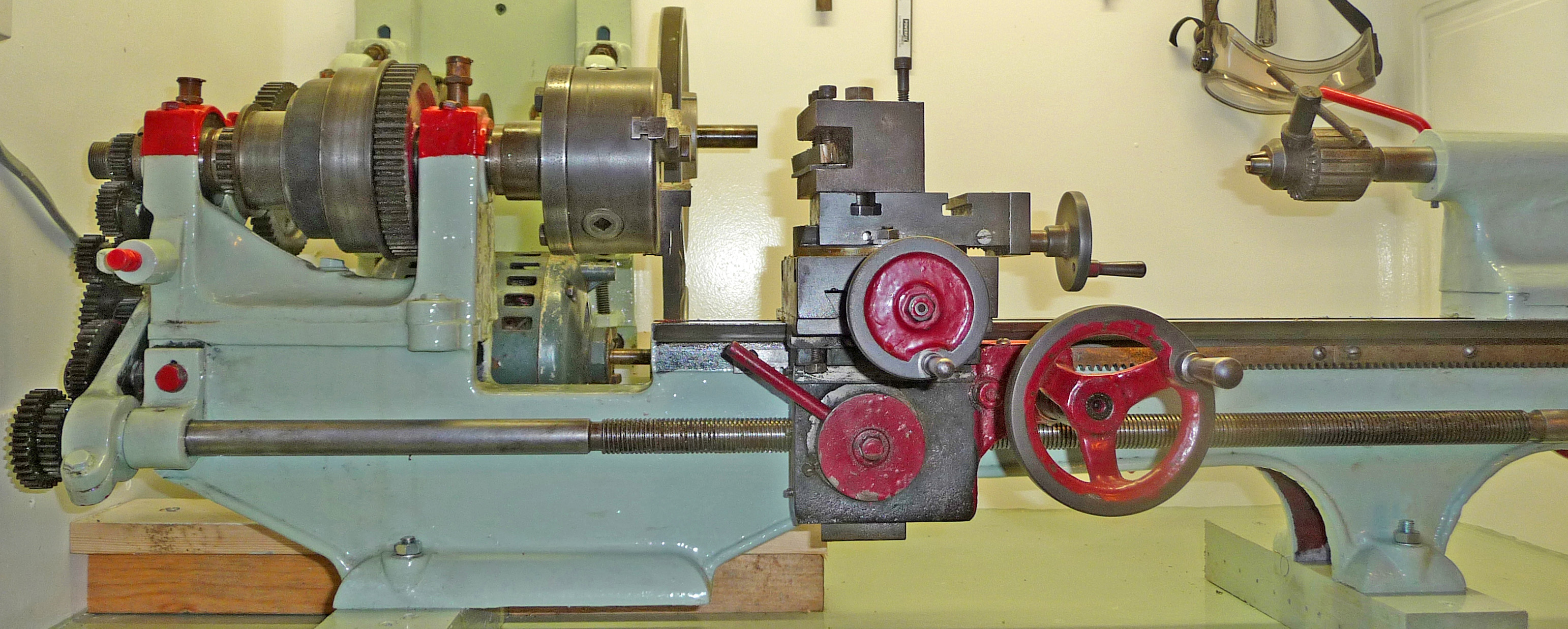
An early long-bed Ideal in remarkably fine and (with the exception of a micrometer dial on the cross-slide screw) exceptionally original condition. This model has the draw-in cone bearings (a single taper at the front and a double at the rear. Note the headstock casting around the bearings - this has been left in exactly the same form as used for the earlier split-bearing type, even to the holes being cored ready for drilling and tapping to take the bearing compression screws. |

|
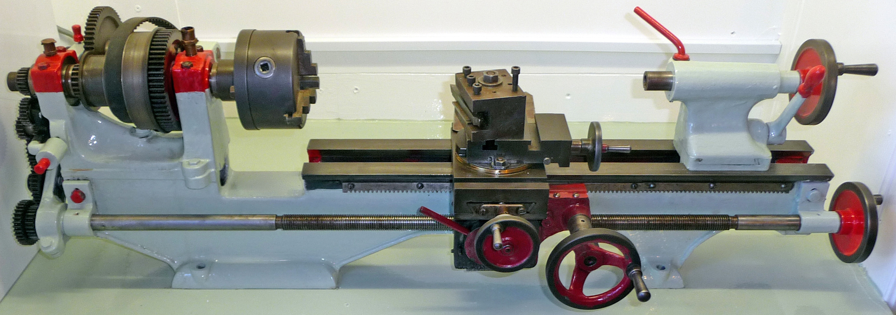
A V-belt-drive machine from the final years of production with a stronger, flat-faced headstock casting carrying cap-type bearings - an unusual fitting to find on any small, inexpensive lathe of the time. Although V-belts were increasingly popular, the lathe could still be ordered with a flat-belt drive, as shown below. |
||
|
|
||
|
and directly-geared handwheel carried on a slender (cast-in) bracket |
|
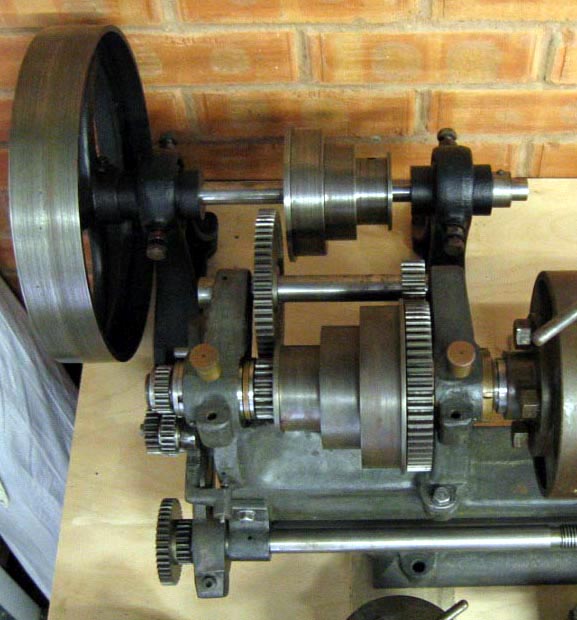
headstock and "draw-in" headstock bearings . |
|
|
||
|
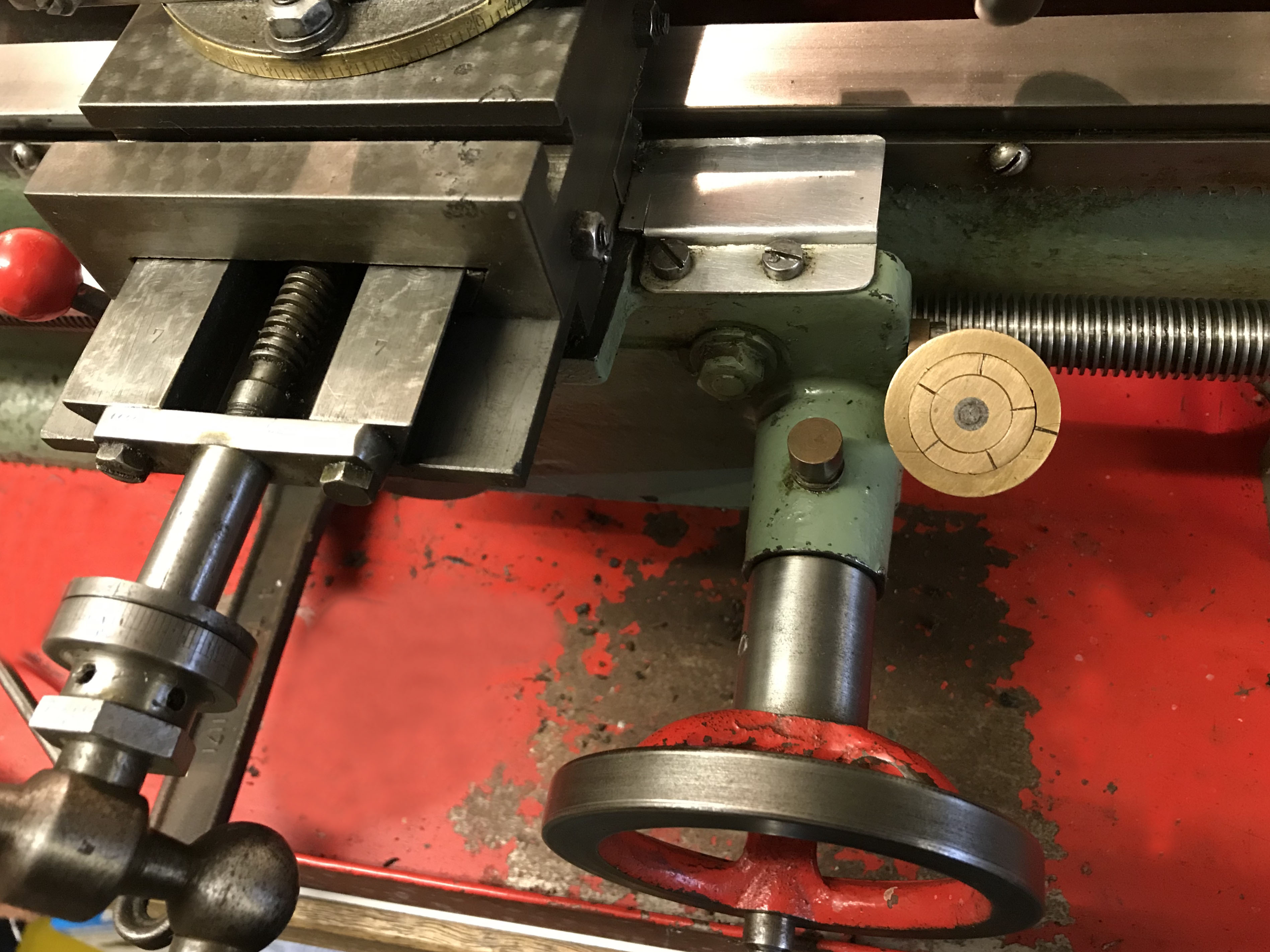
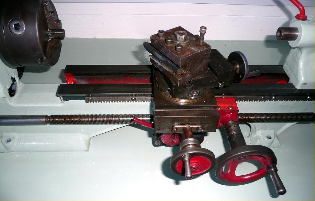
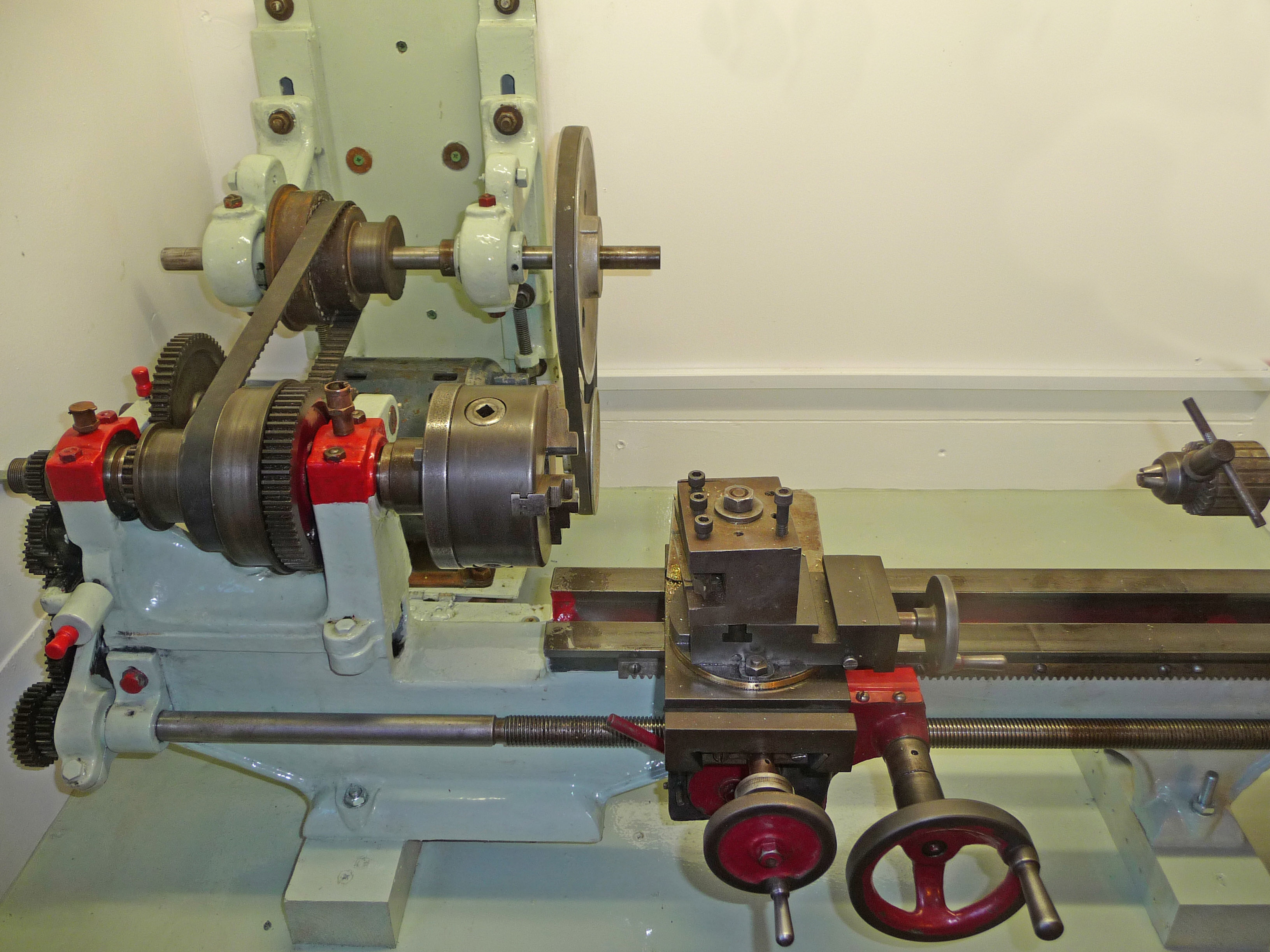
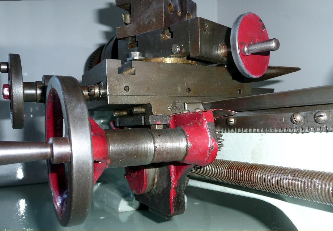
All Ideal lathes appear to have been fitted with not only a T slotted cross slide, but a T slotted top slide as well. This was a useful arrangement if you wanted to mount three toolposts - and very useful if the end of the long-travel slide snapped off in a moment of unguarded optimism as you buried the turning tool into the face of a three-inch diameter billet of EN45 - at least you had two more T slots into which the tool could be mounted. |
||
|
This "as-found" Ideal still has the original design of split-bearing headstock casting but in this case carrying the later "draw-in" tapered bush. |
||
|
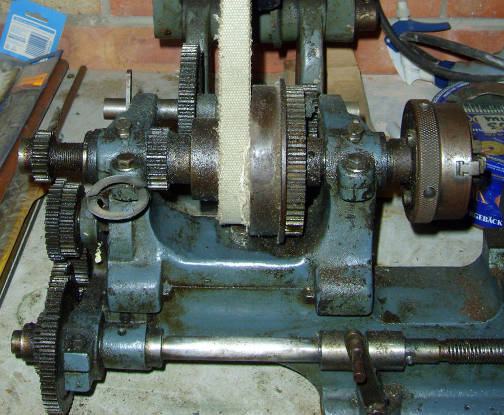
A lighter 3-inch centre height Ideal, intended for drive by a round belt and sometimes found badged as a "Willimott". Introduced during the late 1920s, this cheaper version could be had with either a single swivelling top slide (as shown) or, at extra cost, a proper compound slide rest. The a full leadscrew nut bolted to the underside of the saddle (a dog clutch was standard equipment) while the headstock bearings were unusual in having long, distinctive extensions to accommodate the pinch bolts. |
|
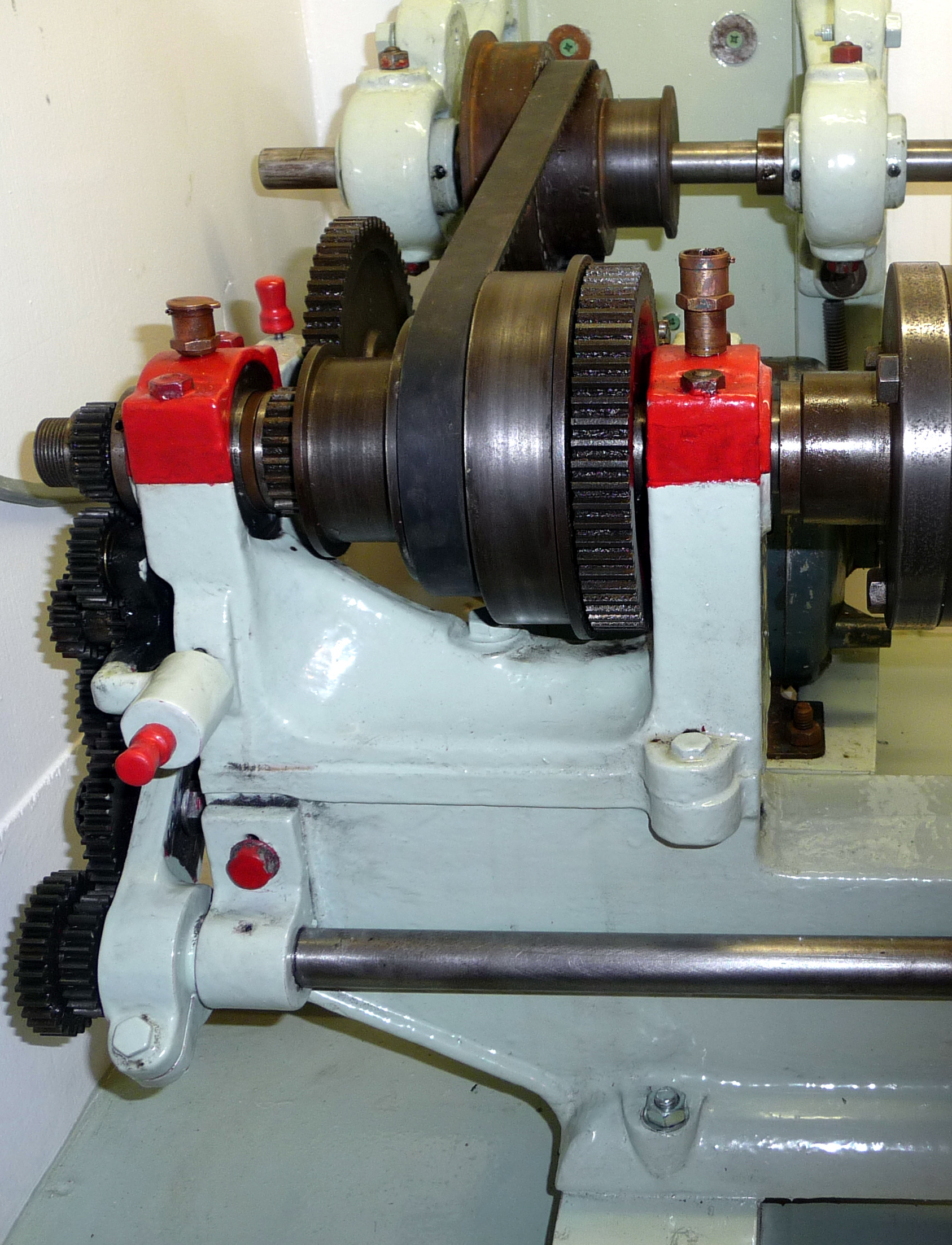
Distinctive extended front flanges to the headstock bearings of the Willimott Ideal. Note the dog clutch (necessary to cope with the full leadscrew nut and the heavy backgears. |

|
Is this an Ideal ? It may be, yet there a number of significant differences: the headstock is bolted down through a flange at the front with provision for screws to pass through the front of the bed and push it backwards against a machined vertical surface. The cross slide has a bracket bolted to its end face and covered ways whilst the top slide, which would be a first on an Ideal, does not carry T-slots. The tailstock is also of an entirely new, much more rugged design. |
|
Home Machine Tool Archive Machine-tools Sale & Wanted |
||