|
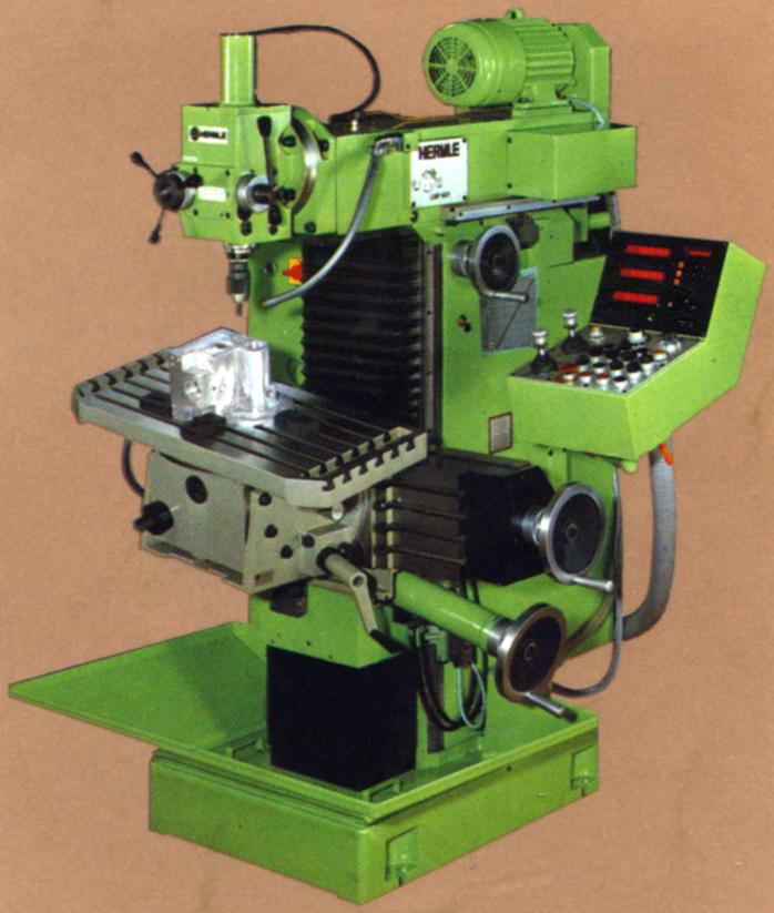
Hermle UWF-800 and UWF-801
Almost identical, the 801 was distinguished from the 800 by a motor mounted on top of the overarm (instead of protruding from the rear face), its controls contained in a pedestal unit and the fitting as standard of a DRO system.
With a particularly robust cast-iron main column dowelled and bolted to a heavy, internally ribbed baseplate that held a coolant tank, the machines were almost identical in appearance to the smaller UWF-700 - but with an enhanced work-holding capacity. Designed for both toolroom and production work their versatility was enhanced by twelve spindle speeds that spanned, to the customer's choice, either 45 to 2000 r.p.m. or (at extra cost) 63 to 2800 r.p.m. Driven by a 3 or 4 kW. Motor, the millers had both enough power and a sufficiently wide speed range to enable the tackling of a wide variety of work. The horizontal spindle, running in high-precision taper roller bearings, had it speeds changed by the juxtaposition of levers mounted on the ram's right-hand face. Gears and shafts were all made from high-quality, heat-treated steel with the teeth ground with some, if not all versions, equipped with pressure lubrication with the oil filtered and passed through a serpentine-type water cooling system before being recirculated.
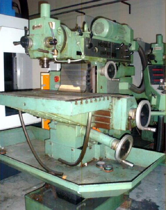
Fitted as standard was a vertical 800 mm x 220 mm table (with four 12 mm T-slots on 45 mm spacing) fastened to which was a plain, non-tilting 800 mm x 350 mm (later increased to 800 mm x 395 mm) horizontal table with six 14 mm T-slots on 63 mm spacing. Feed travels varied according to whether they were hand or power-driven being, respectively, 510 and 500 mm longitudinally, 450 and 430 mm in traverse (on the head) and 410 and 400 mm vertically. Table feeds, driven from a stepless variable-speed 1.5 kW motor through electro-magnetic clutches, were infinitely variable from 4 to 1600 mm/min in both horizontal directions and vertically at 4 to 1000 mm/min - the fastest rate in each case also doubling as "Rapids". Control of table direction was by two joysticks with speed selection on a dial and speed changes by a potentiometer knob. These were mounted on a separate consul (carried on a swing arm pivoting from the right-hand face of the main column) that also included push buttons and switches for the various accessories including hydraulic tool clamping, crawl feed, motor brake, coolant, spindle start, stop and reverse direction, emergency stop and the digital read-outs. If NC control was fitted the panel also included all the associated functions required, including an input keyboard.
Overload protection for the drives was provided both mechanically, by a factory-set torque limitation on the clutches, and by electrical overload. Feedscrews (with pitches of 4 mm longitudinally, 2 mm laterally and vertically) were hardened and ground (a recipe for long, wear-free life) and ran through split nuts that could be adjusted to eliminate snatch on climb milling (with the table feed in the same direction as the rotation of the milling cutter) on both horizontal and lateral feeds. To prevent wear and improve reliability (as on many other makes of the same type) bellows were fitted to guard both slideways and screws. Although most models were fitted with manual table clamps, the factory did offer the option of hydraulic clamping, though it appears to be a rare fitting.
Over the years, several types of head were offered including a standard vertical head driven from the horizontal spindle (most found mounted on a very convenient swing-away davit) with some versions having both quick-action drilling and fine feeds and others just the former; a horizontal conversion unit that was bolted in place on the end of the horizontal overarm Interestingly, standard machines were equipped with a special drawbar key which, for safety, had to be returned to its storage pocket before the machine could be started.
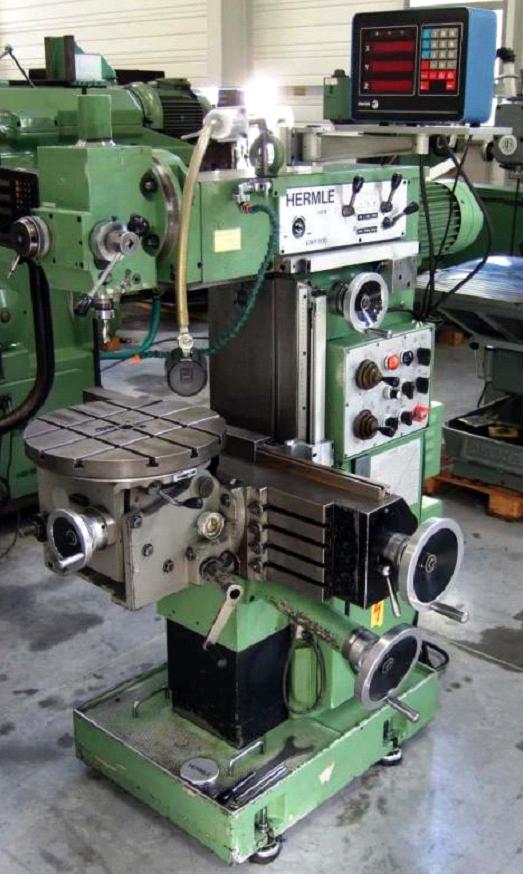
One essential requirement for success when using this type of milling machine is usually the availability of different tables to mount on the front vertical. However, in the case of the Hermle, the makers incorporated a most sophisticated and robust unit that, as standard, could be swivelled on its vertical axis, tilted 45 degrees left and right from central and nodded 45 degrees front to back. Based on a heavy box casting secured in place by eight T-bolts, the central part could be either a large table with rounded end faces (with tilt and angle movements controlled by handwheels or crank handles) or a dividing unit with interchangeable division plates.
As part of Hermle's commitment to quality engineering, all versions of the miller were fitted with a centralised, pump-driven lubrication system with oil sent via metering valves to all slideways, feedscrews and feed-screw nuts. A warning light illuminated if the system failed.
Several enhanced features were available at extra cost including power tool clamping on both horizontal and vertical spindles. Secured in the spindle by a screw-bolt insert, the design enabled ordinary and inexpensive standard ISO 40 tools to be used. Also listed was hydraulically-driven power clamping of the slideways, automatic spindle speed changing, 3 axes dial-gauge and slip-gauge platforms, 2 or 3-axis digital readouts (the make could be chosen by the customer for factory fitting), positioning control with a digital readout, NC point-to-point control and a version fully equipped with CNC contouring control..
|
|