YOU SPENT $2000 ON WHAT???
Page 1 - Page 2 - Page 3 - Page 4 - Page 5 - Page 6 - Page 7 -
15 April 2002
I pressed on. After doing the web pages I called Hercus in South Australia again. They haven't made or supported the 9" lathes for some time, and I'd been playing phone tag with someone who might be able to help. This time I got put through to Doug, a toolmaker, who had actually made the lathes. Yes, the bearing preload was too much, and I'd have to adjust it.
The screwed collar on the end of the spindle, which is used to adjust end float on plain bearing headstocks, is used as a fine preload adjustment on the roller models. I'd done right to slacken it off, but the necessary step I hadn't done was to tap the spindle with a hammer to physically shift the inner race along the spindle. Obviously you don't whack the daylights out of it, but a medium tap is OK. If the front (chuck end) bearing is too tight, you may also have to tap the spindle back as well.
Doug also gave me a couple of tips about the countershaft and wished me luck. A very good phone call.
So what is the appropriate preload? With the back gear pin pulled, the spindle should turn 3/4 to 1 turn before stopping. With a chuck, 3-4 turns. The bearings should not get hot.
I adjusted the collar and gave a few light taps using a brass block and medium hammer, and ran the lathe at medium speed for ten minutes. The bearing caps were a little warm, so I adjusted it again. Another fifteen minutes at high speed and the caps were barely warm, and the spindle ran freely. Hooray!
After another six hours cleaning and scraping (did I mention the paint on top of swarf and grease?) the apron was ready to put together.
The reassembly order is quite important. The exploded parts diagram isn't a lot of help, it is very possible to spend time putting bits in which prevent you from locating or fitting other parts later. The photo sequence here should be of benefit if you ever have to do this job on your lathe.
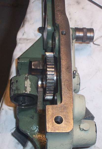
First is the sector plate and gear, with the power feed handle pinned to the shaft. This took some time getting right because the pin was slightly bent - I did my best to straighten it - and each time it went fully home the clearance got too tight. Eventually I reached a happy medium where the lever is still stiff, but the pin is right home.
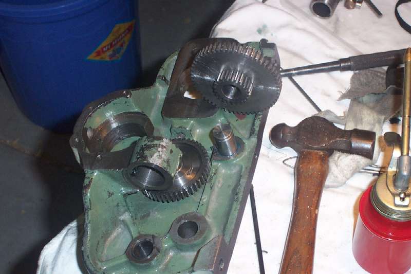
Next is the pin and gear for the cross feed. A grub screw locates the shaft in the correct orientation for the oil hole, and a wire clip outboard of the gear stops it falling off. This is the time to fit the wick oiler and felt pad to the worm bearing (centre of the photo). The wick goes up through the casting and I found it impossible to re-use the old one - it had swollen with oil and age and just wouldn't go. I made a new wick out of an old boot lace, doubled it over and pulled it through with a loop of fine but strong phos-bronze wire.
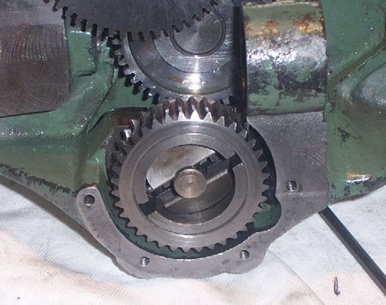
Next is the clutch. This is a job requiring five hands and eyes in the back of your head. Not quite, but it was a painstaking task getting it all lined up at the right place and right time. The cross pins in the shaft are just over 90 degrees out in the photo - they have to be lined up with the drive dogs on the sleeve. The clutch shoe halves push in on either side of the drive dogs and have to be held against the shaft spring while you slide in the two semicircular leaves and lock them in place in the cutouts just below the end of the shaft - and then you quickly run the star knob up using your other hand to stop it all falling apart again. Whew!
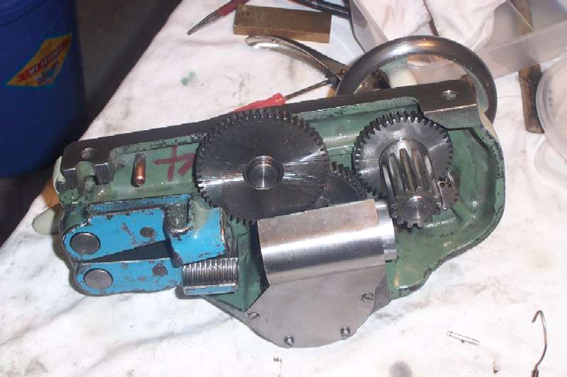
The clutch fully assembled. Turning the star wheel clockwise pulls the shaft, which forces the butterfly leaves against the inside of the shoes, which grip the inside of the worm gear. Quite a contrast from what it looked like before I stripped and cleaned it.
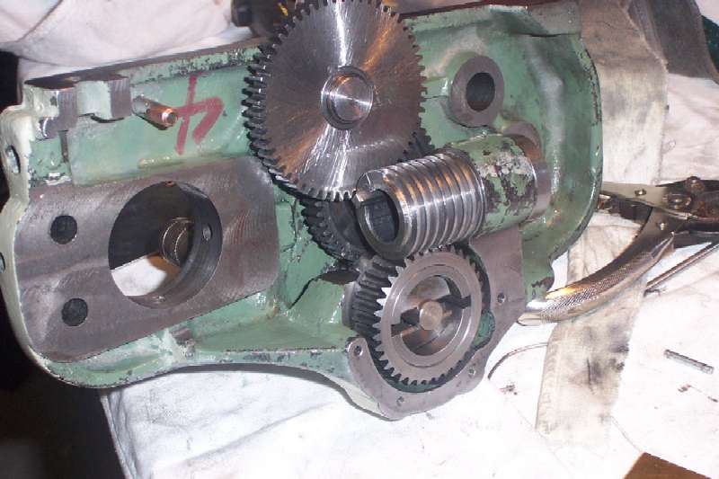
On goes the worm. I found it easiest to insert the key on the bench, then put the worm in the bearing. Note that due to the way the worm is machined, you have to rotate it to a thin part of the end tooth to get it to go over the worm wheel. Once in the bearing, the end collar screws on and the locking pin inserted. This pin does two things - stops the collar unscrewing and stops the key from sliding out. With the wear in the setup, I found that an extra quarter of a turn on the collar would have been beneficial. One day I'll either drill another hole in the collar, or fit a brass or phos-bronze shim washer to take up the end play.
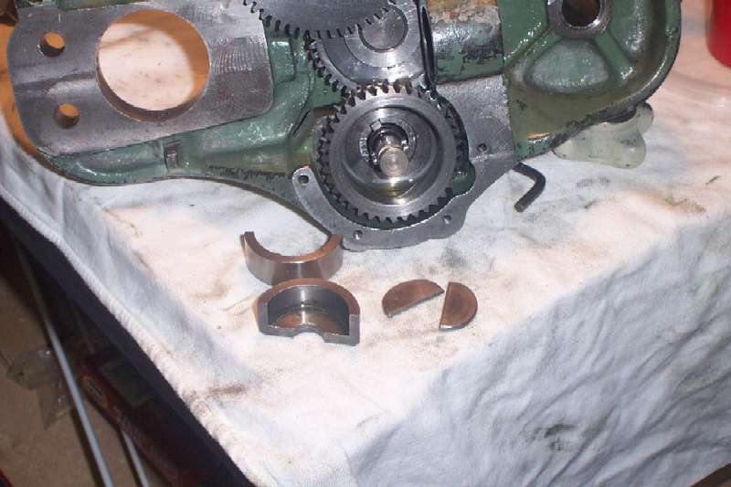
Next is the handwheel and rack gear. The shaft for the rack gear is held in with a grub screw from underneath, again to align the oil hole vertically. Earlier photos of the assembled apron show the oil holes pointing any which way - not that it mattered, they were full of grunge and paint.
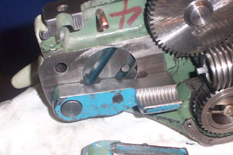
The clasp nut lever and nuts are next. Don't forget to put in the interlock pin that goes between the power feed sector plate and clasp nut lever hole. The rounded end of the pin goes on the sector plate, the pointy end out. No need to ask how I found that out. A sprung locating pin goes up from underneath to hold the clasp nut lever in alignment. The bevel on the end of the pin only goes one way - you will need to do a trial assembly and move the lever. If it is incorrect it will not be smooth and slight tightening of the grub screw will lock the lever. Pop it out, rotate the pin 180 deg and reassemble. Then the clasp nuts can be fitted and the pins nutted up from the other side.
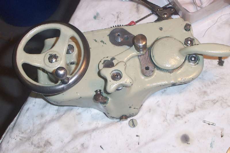
This is what the apron should look like. I don't care about the paint falling off as mechanically it is pretty sound. I had to remove the oiler and spend a bit of time digging crud out of it. God knows how it got in there - probably from swarf in the oil settling at the lowest point.
The assembled apron from the other side. The copper pipe is from the front oil hole, which should (might!) drip oil into the well cast into the top clasp nut. The well has holes at either end for oiling the pivot pin and the leadscrew. There is a gasket on the inside of the stainless worm gear cover - it forms an oil bath for the worm assembly, which also transfers oil to the other power feed gears via the teeth.
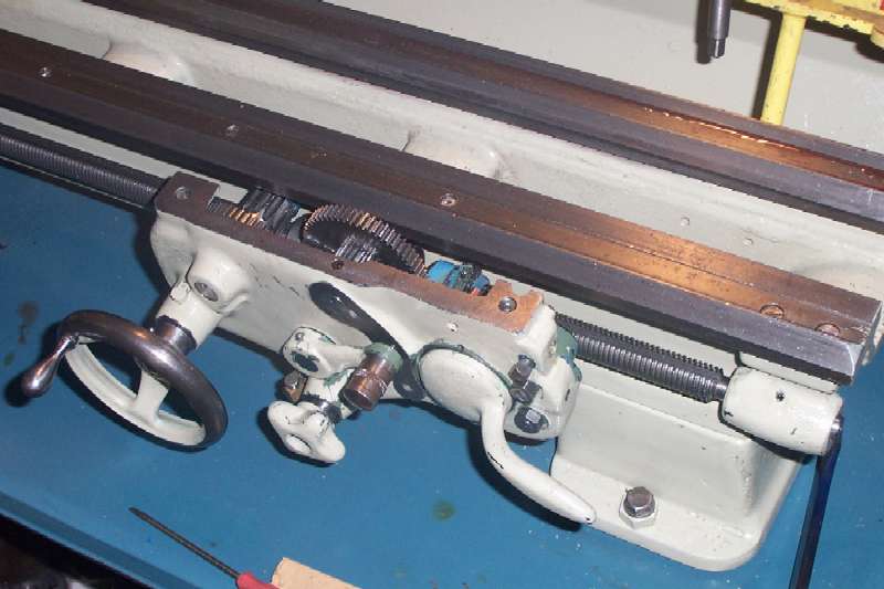
Reassembly of the saddle is the reverse of pulling it apart. I slid the apron past the bed foot and then put the leadscrew outboard bearing back on. Slight technical hitch - there is no way to get the saddle lock clamp in. I had to take off the leadscrew bearing and drop the apron down, put in the clamp, and then put the saddle on. Once the saddle lock screw had picked up the threads in the lock clamp, I was able to put the leadscrew bearing back on and do up the screws holding the apron to the saddle.
Testing under power revealed... absolutely bloody awesome performance. By this stage it was two in the morning, but I wasn't going to bed until I'd tested it thoroughly. The place on the rack where the tooth was bent and repaired still caused a problem when screwcutting - unless the handwheel was kept turning, the rack pinion got out of sync and jammed against the part-formed tooth. That's something I'll have to watch when screwcutting right down the end of the bed (about where the apron is in the above photo). Other than that, screwcutting in both directions is smooth and even. Power feeds are brilliant - both longitudinal and cross feeds are smooth and silent, and joy oh joy the clutch needs about one sixteenth of a turn to fully engage and disengage. Not like the three or four hefty turns needed before I stripped and cleaned it. More to the point, as long as one of the kids doesn't wind the star knob off, I won't need the locking screw... 8-)
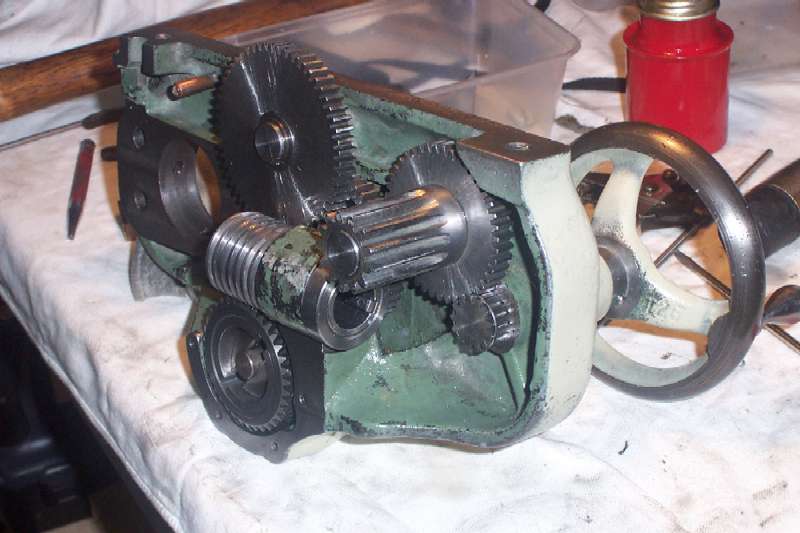
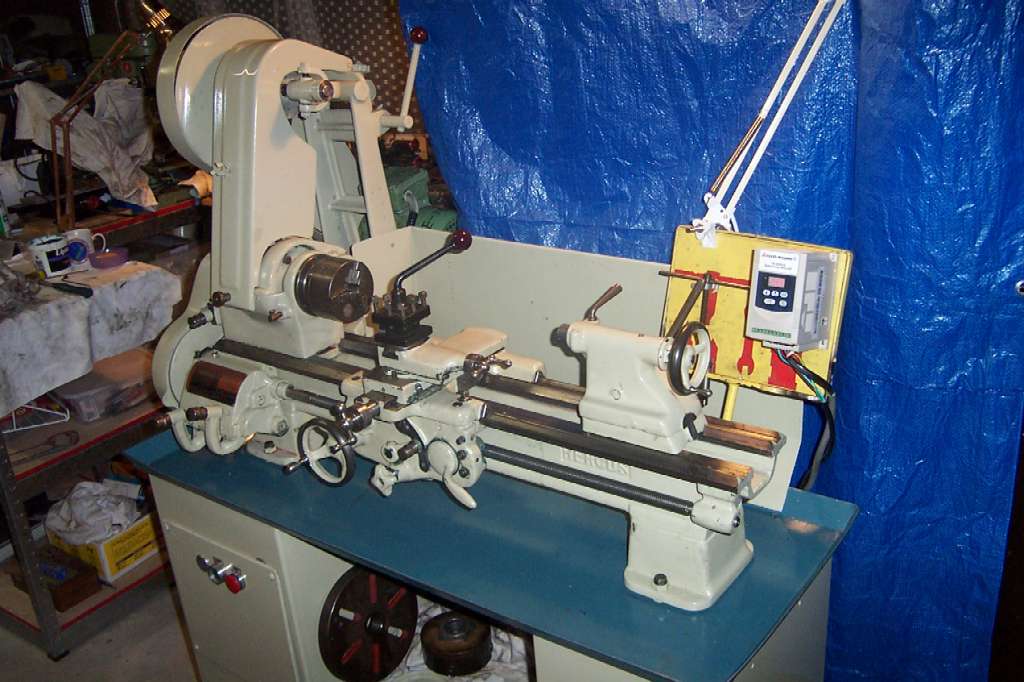
Last of all, this is what the lathe looks like now - should have looked like from the rebuilders, but right now it is very much MY machine as I've got MY hands dirty and I've built up an incredible first hand knowledge of how MY machine works. Knock me down, paint me black and colour me happy!
Cheers
Charlie
Page 1 - Page 2 - Page 3 - Page 4 - Page 5 - Page 6 - Page 7 -