 |
|
|
|
|
|
|
|
|
|
|
|
|
|
|
|
|
|
|
|
|
|
|
|
|
|
|
|
|
|
|
|
|
|
|
|
|
|
|
|
|
|
|
|
|
|
|
|
|
|
|
|
|
|
|
|
|
|
|
|
|
|
|
|
|
|
|
|
|
|
|
|
|
|
|
|
|
|
|
|
|
|
|
|
|
|
|
|
|
|
|
|
|
|
|
|
|
|
|
|
|
|
|
|
|
|
|
|
|
|
|
|
|
|
|
|
|
|
|
|
|
|
|
|
|
|
|
|
|
|
|
|
|
|
|
|
|
|
|
|
|
|
|
|
|
|
|
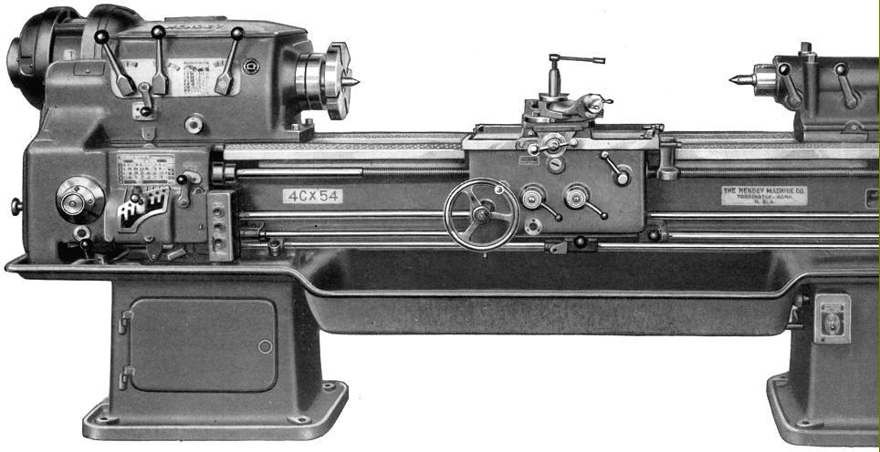
Manufactured to typically high Hendey standards the heavy-duty 4C Manufacturing lathe swung 16 7/16" over the bed, 9 inches over the cross slide and could be ordered with a between-centres capacity of between 30 and 90 inches at intervals of 12 inches.
Deep and wide, the well braced bed was straight, there being no need for a weakening gap on a machine intended for production use. Twelve spindle speeds were provided powered by a dynamically balanced, 7.5 h.p., 1800 r.p.m. motor flange mounted against the headstock input shaft. Inside the headstock the thirteen ground-finished gears were all (like their splined shafts) made from oil-hardened alloy steel and heat-treated.
A choice was offered not only of motor speeds but also of the gear on the output side of the clutch and its mating partner - these being available in a set of four pairs. Everything in the headstock ran in either taper roller or other anti-friction bearings with the gears splash lubricated - but with oil to the bearings being filtered through pads carried in pockets set above them.
Continued below:
|
|
|
|
|
|
|
 |
|
|
|
|
|
|
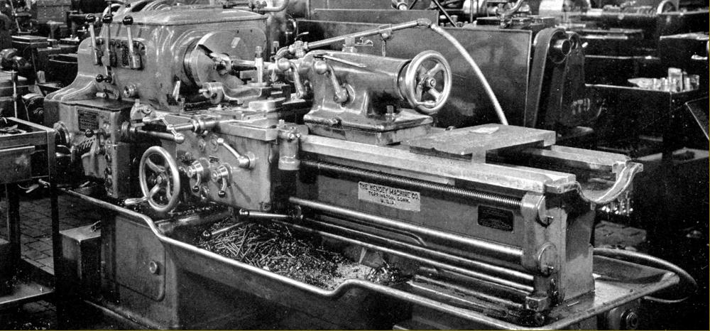
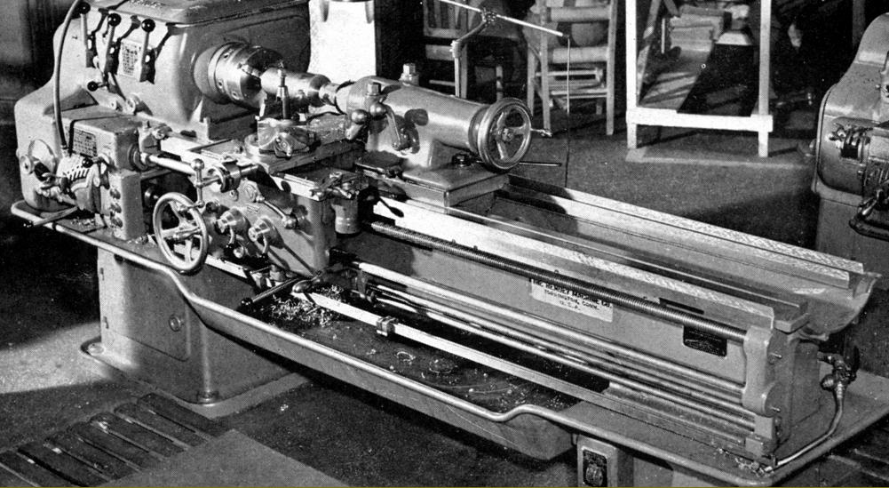
Hendey 4C manufacturing lathe as manufactured circa 1938
|
|
|
|
|
|
|
|
|
Continued:
Combining different sets of input gears with a motor speed of 1200 r.p.m. the four ranges suggested by the makers were 16 to 655 r.p.m., 20 to 800 r.p.m., 25 to 1000 r.p.m. and 30 to 1200 r.p.m. Other motor speeds provided:
1500 r.p.m. gave 20 to 820 r.p.m., 25 to 1000 r.p.m. and 30 to 1200 r.p.m.
1800 r.p.m. gave 25 to 1000 r.p.m. and 30 to 1200 r.p.m. with a final alternative of a 2-speed motor running at 900 and 1800 r.p.m. that produced 24 speeds spanning (with the appropriate gear set) 13 to 525 r.p.m. or 26 to 1057 r.p.m.
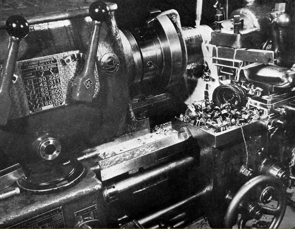
Drive was transmitted though an oil-immersed, multi-plate clutch combined with a cone-type brake with the 1.5" bore spindle forged from a heat-treated, oil quenched alloy steel (the process ensuring a proper grain structure) and running in pre-loaded, super-precision taper-roller bearings. The customer was offered a choice of either an "American Long-nose taper" or a "Cam-lock" spindle nose with, at the other end of the spindle, a common Hendey fitting - the provision of marks to assist with the cutting of multi-start threads of up to six starts: the technique was to cut the first thread in the normal way then turn the spindle by hand so that a "0" mark on the spindle aligned with an inscribed line on the headstock. The knurled knob between the two left-hand speed control levers was then turned so that the pointed indicated "Feed Gear Out" (or when fitted with the ordinary quadrant-lever control system into the neutral position).
Spindle speeds were changed by the juxtaposition of three levers on the face of the headstock with electrical start, stop and reverse operated by a third-rod system with one control lever pivoted from the right-hand corner of the apron and the other near the screwcutting gearbox. The shaft's linkage passed through the bed, just in front of the headstock, to adjustable rods connected to the spindle clutch and brake unit.
As an alternative to the normal (internally mounted) headstock-mounted tumble-reverse mechanism (to change the feed direction of the carriage), the 4C could be equipped with a time-saving device whereby a control mounted on the apron provided a power feed and screwcutting reverse that could be operated while running at high spindle speeds When fitted with this "quick-return" arrangement, in order to provide a neutral position, a manually operated in-and-out feed gear on the headstock was supplied, activated by a knurled knob fitted between the two left-hand speed-control levers.
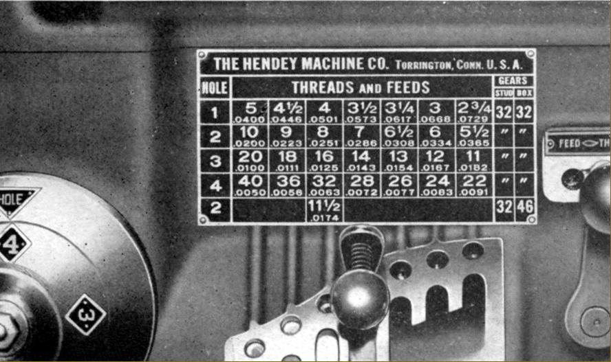
Able to generate 28 thread pitches (from 2 ¾ to 40 t.p.i.) and 28 rates of feed (from 0.005" to 0.729" longitudinally), the screwcutting gearbox was of the traditional Hendey-Norton type with three compartments: to the left was a compound gear train of oil-hardened alloy steel gears sliding on splined shafts with a dial used to move the two selector arms; in the centre was a cone of seven gears (with a trigger-released sliding tumbler selector) and on the right a third cluster of gears with a lever to direct drive to the leadscrew or feeds' powershaft - only one able to be selected at a time. The leadscrew was engaged through a positive, multi-tooth clutch, the powershaft through a similar arrangement but in addition provided with a friction device to give safety-overload protection. All shafts ran on anti-friction bearings, including the leadscrew that was, additionally, provided with a means of adjusting out wear in the thrust pads so that it would rotate freely yet without end play (Hendey leadscrews were manufactured in-house and guaranteed to be accurate to within plus or minus 0.001" per foot of travel; however, at extra cost a super-precision leadscrew could be furnished). To obtain a range of finer power feeds - while leaving the threading range unchanged - it was possible to mount different gears inside the right-hand compartment, though this process involved considerable dismantling and was not intended as a short-term measure that the operator could manage.
As a production machine some means of automatically stopping the longitudinal drive was essential (an operator might be attending to more than one lathe at a time) and the Hendey did not disappoint, two types of mechanism being fitted: one a simple automatic stop rod (a flat bar beneath the rod that controlled the spindle clutch), the other a multiple unit that worked in both directions with six stops that the operator could arrange as needed. The knock-off arrangement could be used with the standard feed set-up or with the high-speed apron reverse. An automatic disengage was also available for the cross feed, this 5-position device being self-contained and able to be bolted to the apron wings to either the left or right-hand side of the cross slide
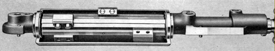
Cast in one piece, the apron had its lower section in the form of an enclosed box to provide support for both ends of the gear-carrying shafts and an oil reservoir. Both cross and longitudinal feeds had positive engagement by clutches with quick-acting lever controls that overcame the normal reluctance to release under a heavy cutting load by incorporating an accelerated release mechanism on the downward stroke. Built into the base of the apron was an oil pump, activated by turning the carriage handwheel, that distributed filtered lubricant to the apron internals, the leadscrew nuts (but only when engaged) and the bed and cross-slide ways. Excess oil was drained back into the sump while a sight class provided a means of checking the level. Fast-running gears were mounted on shafts running in ball races and worms gears made of hardened steel.
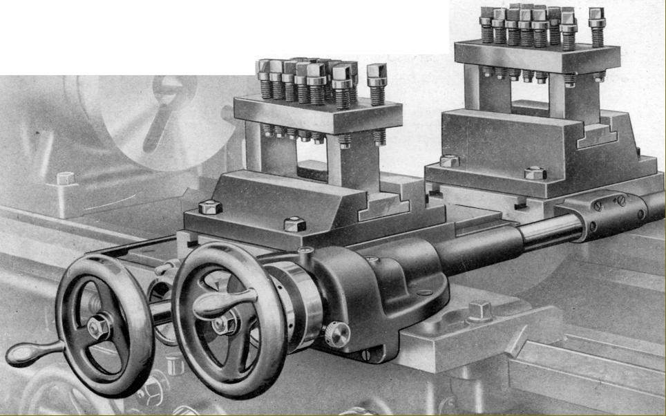
With an especially long apron and the cross-slide ways placed exactly on its centre line, the carriage was able overlap the front of the headstock casting to get the toolpost up to the spindle nose. As befitted a proper manufacturing lathe the slide rest assembly was of a special type composed of two independent cross slides, mounted on the same ways, with one positioned at the front and the other to the rear. The front slide could be operated by hand or under power, the rear slide by hand only with its handwheel moved to the right (to provide clearance between it and the other handwheel) by being geared to its feed-screw. The maker offered various toolposts, including a particularly well-made and rugged 4-way type with a clockwise rotation of the handle releasing a locking pin allowing the unit to be turned by hand; rotating the handle clockwise locked the toolpost down. As a finishing touch, each of the four slots had a built in rocker shoe allowing each tool to be individually adjusted over a small range.
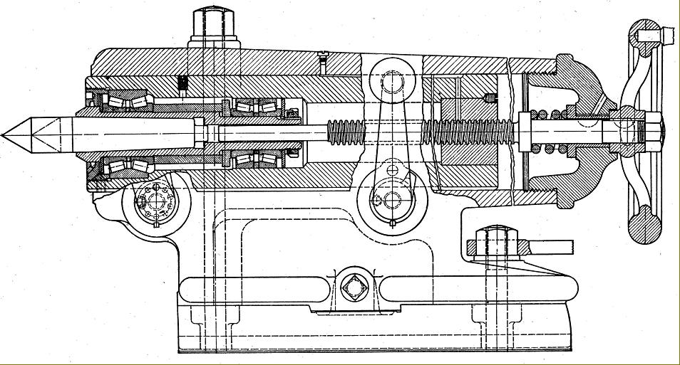
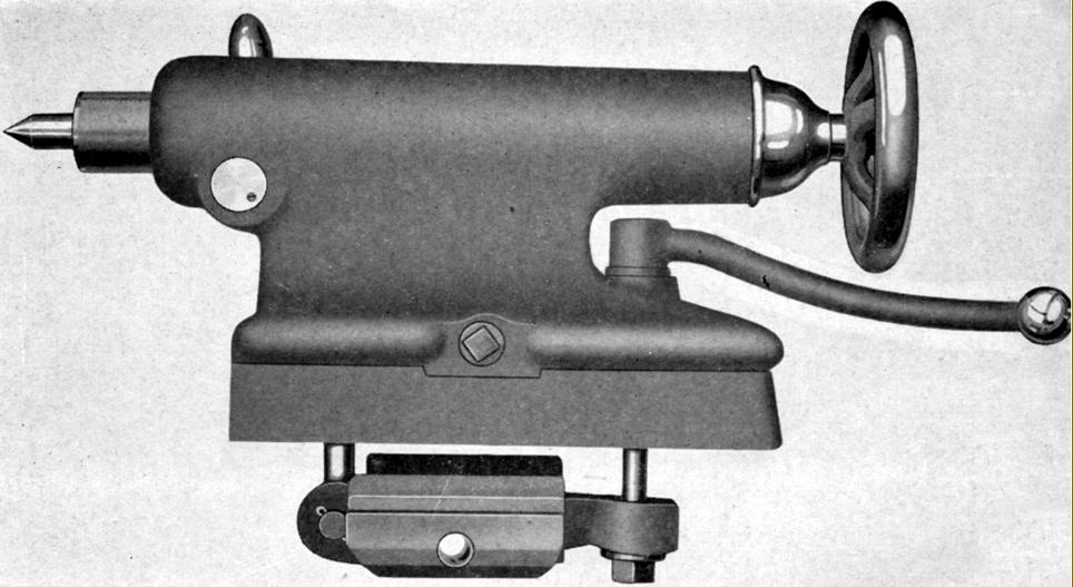
Fitted as part of the regular equipment was a heavy-duty tailstock with its spindle 4.5-inches in diameter, having 9 inches of travel and engraved with a ruler marks down to thirty-seconds of an inch. The makers obviously intended this to be a most robust assembly with two independent spindle clamps provided (one at the front and the other at the rear) and the body secured to the bed by two clamps and three bolts. At extra cost the spindle could be equipped with a rather unusual built-in rotating centre that used a pair of precision taper-roller bearings. A heavy coil spring was fitted between handwheel and spindle - apparently intended to help the operator overcome some of the resistance caused by the considerable end thrust. As an option, a lighter, more easily handled tailstock could be provided. This had a 25/8" diameter spindle in carbon-steel with 7 inches of travel and a bed lock patented in 1928 (1,666,484) by one Constant Bouillon of Torrington (assigned to the Hendey Company)..
|
|
|
|
|
|
|
 |
|
|
|
|
|
|
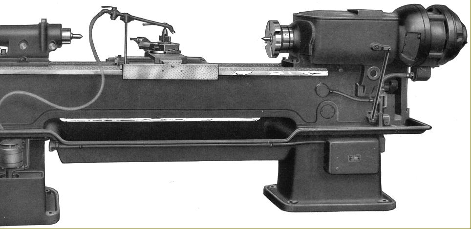
Rear of the Hendey 4C Manufacturing Lathe showing the integrated mounting of the motor
|
|
|
|
|
|
|
 |
|
|
|
|
|
|
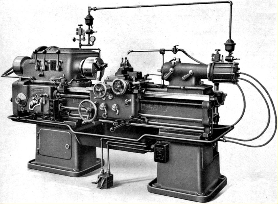
Hendey 4C Manufacturing Lathe fitted with Logansport air-control equipment that opened and closed the chuck jaws, moved the tailstock spindle and powered both the front (and separate) rear tool slides
|
|
|
|
|
|
|
 |
|
|
|
|
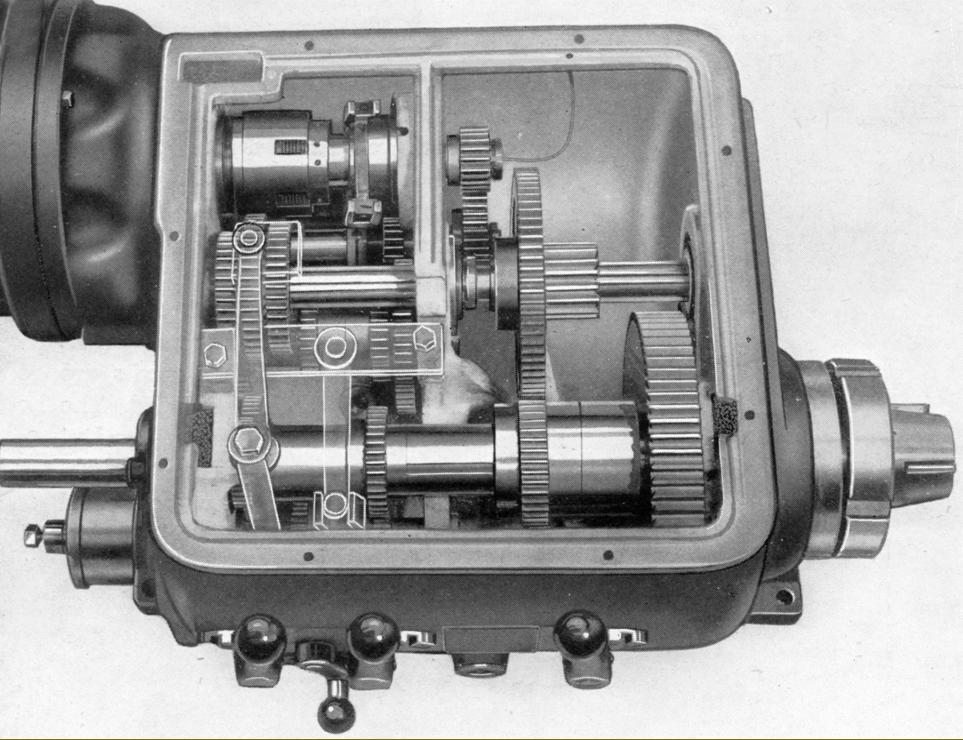
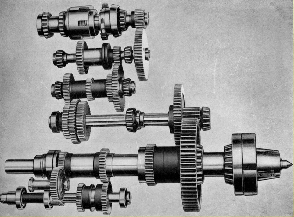
Inside the headstock of the Hendey 4C Manufacturing Lathe: at the back the multi-plate clutch and at the front the 1.5" bore main spindle forged from an alloy steel, heat-treated, oil quenched to ensure a proper grain structure and running in pre-loaded, super-precision taper-roller bearings. The twelve speeds were obtained through thirteen ground-finished gears all (like their splined shafts) made from oil hardened alloy steel and heat treated. Everything ran on either taper roller or other anti-friction bearings with the gears splash lubricated but the oil passing to the bearings first being filtered through pads carried in pockets set above them
|
|
|
|
|
|
|
|
|
 |
|
|
|
|
|
|
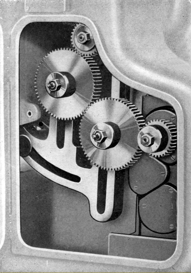
Pictorial schematic of the headstock gear and clutch assembly.
|
|
|
|
|
|
|
 |
|
 |
|
|
|
|
|
|
|
|
|
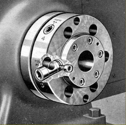
D-Type Cam-lock spindle nose fitting
|
|
|
|
|
|
|
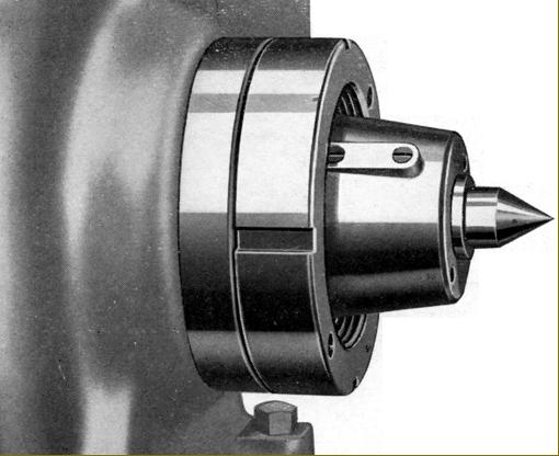
American long-nose taper spindle fitting
|
|
|
|
|
|
|
|
 |
|
|
|
|
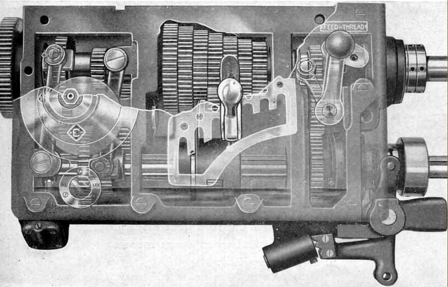
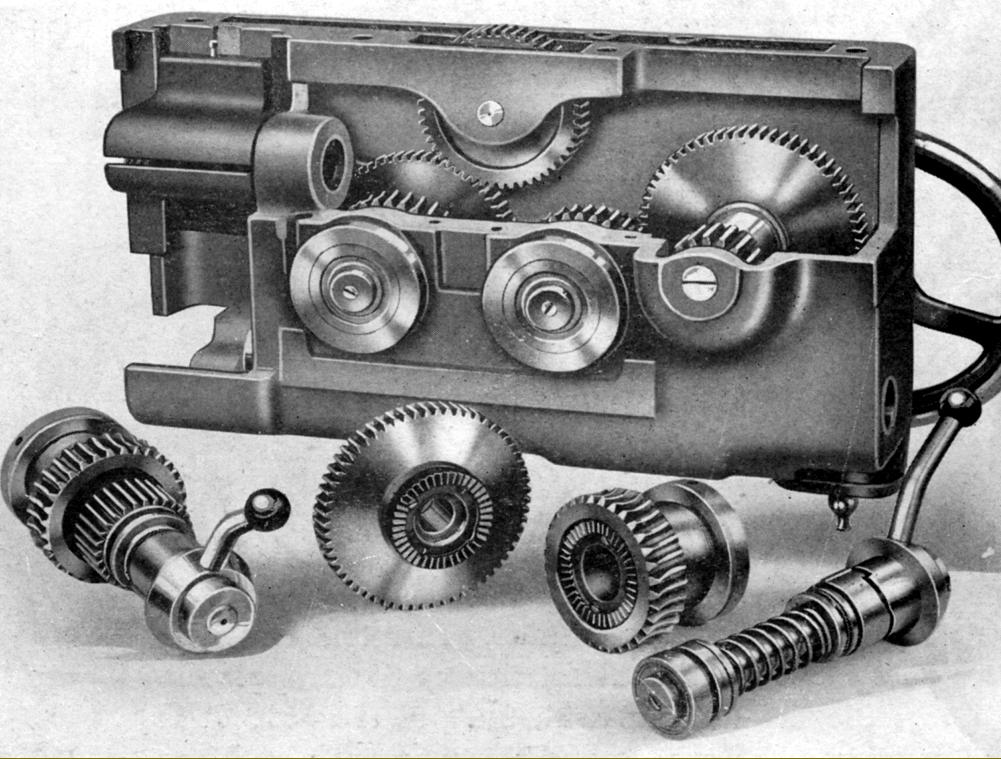
Cut-away and "phantomised" view of the well-known Norton-Hendey screwcutting and feeds gearbox. On the left the primary speed-change gears and their dial selector attached to two selector arms; in the centre the cone of seven gears with a trigger-released sliding tumbler selector and on the right a third cluster of gears with a lever to select drive to the leadscrew or powershaft.
|
|
|
|
|
|
|
|
|
 |
|
|
|
|
|
|
Standard threading range chart on the 4C. To obtain finer feeds while leaving the threading range unchanged it was possible to mount different gears inside the right-hand compartment of the gearbox - though this process involved considerable dismantling and was not intended as a short-term measure
|
|
|
|
|
|
|
 |
|
|
|
|
Changewheels. To ease the mounting of alternative gears to extend the threading range of the screwcutting gearbox twin slotted arms were provided
|
|
|
|
|
|
|
|
|
 |
|
|
|
|
|
|
Hendey 4C Manufacturing Lathe apron. Note the oil level glass
|
|
|
|
|
|
|
 |
|
|
|
|
Cast in one piece, the apron had its lower section in the form of an enclosed box to provide support for both ends of the gear-carrying shafts and an oil reservoir. Both cross and longitudinal feeds had positive engagement by clutches with quick-acting lever controls that overcame the normal reluctance to release under a heavy cutting load by incorporating an accelerated release mechanism on the downward stroke.
Fast running gears were mounted on shafts running in ball races and worms made of hardened steel.
|
|
|
|
|
|
|
|
 |
|
|
|
|
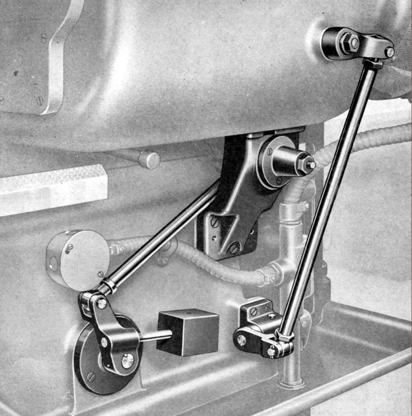
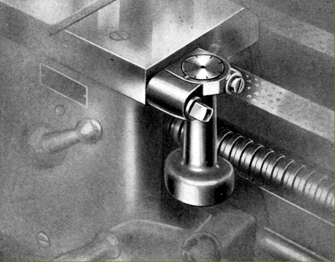
As an alternative to the normal headstock-mounted tumble-reverse mechanism (to change the feed direction of the carriage), the 4C could be equipped with a device whereby a control mounted on the apron provided a reverse that could be operated while running at high spindle speeds When fitted with this device, in order to provide a neutral position, a manually operated in-and-out feed gear on the headstock was supplied, activated by a knurled knob fitted between the two left-hand speed-control levers. The reverse control, operated by a lever pivoting from the right hand lower corner of the apron and duplicated by one beneath the gearbox, passed through a rod laying along the lower edge of the bed then through the bed to the pivot point shown in the bottom left-hand corner of the picture above. From there the linkage passed to the headstock-mounted spindle clutch that effected the change of direction.
|
|
|
|
|
|
|
|
|
 |
|
|
|
|
|
|
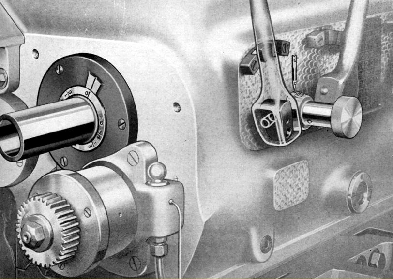
On the left, where the headstock spindle emerges from the headstock casting, can be see the markings that allowed the operator to cut multi-start threads. The technique was to cut the first thread in the normal way then turn the spindle by hand so that the 0 mark aligned with the inscribed line. The knurled knob between the two left-hand speed control levers was then turned so that the pointed indicated "Feed Gear Out" (or into the neutral position when fitted with the ordinary control system shown in the illustration below)
|
|
|
|
|
|
|
 |
|
|
|
|
|
|
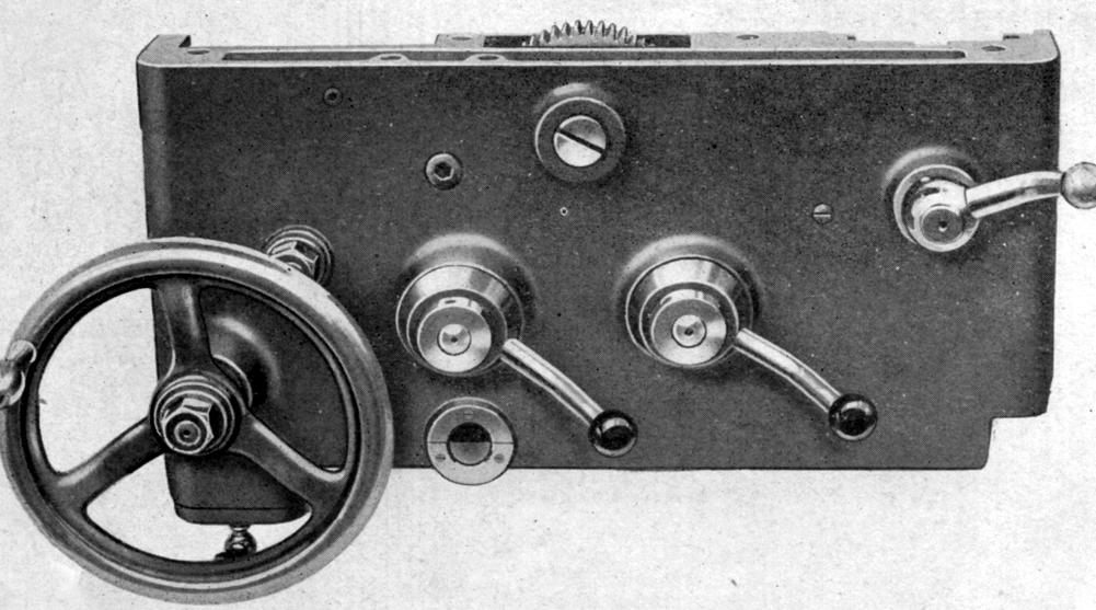
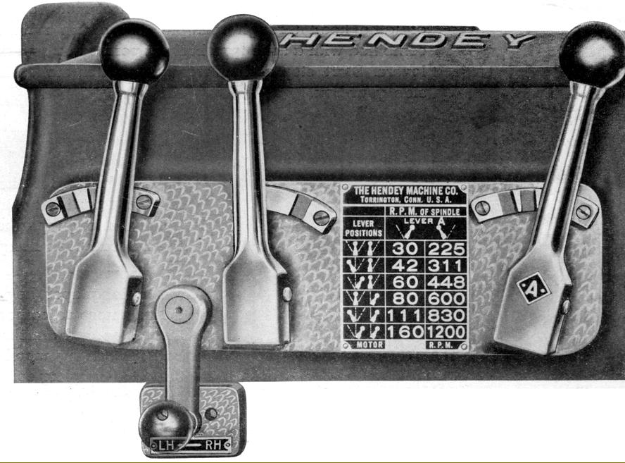
Headstock controls: the vertical levers changed spindle speeds while the quadrant lever hanging down wars used to engage the carriage reverse mechanism - with a non-drive neutral position in the centre
|
|
|
|
|
|
|
 |
|
|
|
|
|
|
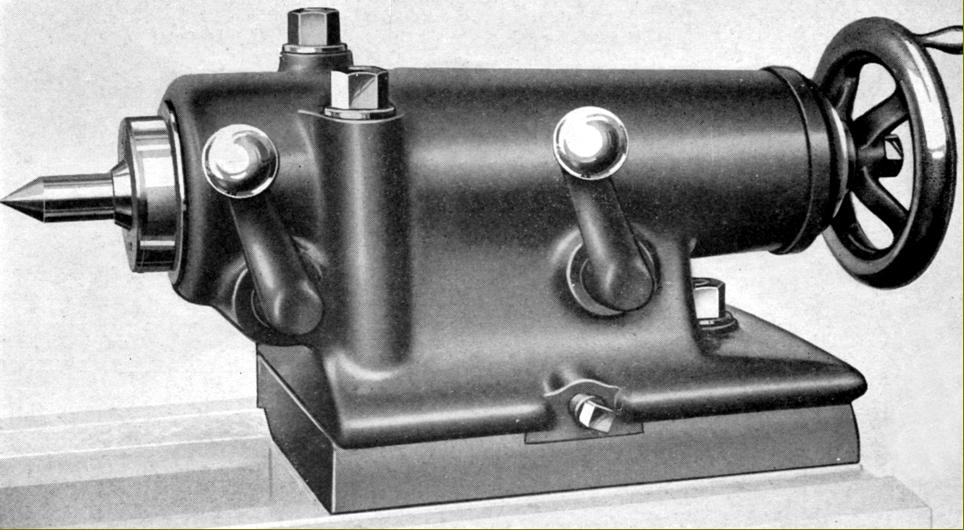
Heavy-duty tailstock fitted as standard to the 4C. 4.5-inches in diameter, the spindle had 9 inches of travel and was engraved with a ruler down to thirty-seconds of an inch. The makers obviously intended this to be a most robust assembly with two independent spindle clamps provided (one at the front and the other at the rear) and secured to the bed by two clamps and three bolts
|
|
|
|
|
|
|
 |
|
|
|
|
|
|
Section through the Heavy-duty Tailstock showing the arrangement of the optional precision taper-roller bearing supported quill - a most unusual built-in rotating centre. Note the spring provided at the end of the assembly - designed to help the operator overcome some of the heavy resistance caused by the end thrust. 4.5-inches in diameter, the spindle had 9 inches of travel and was engraved with ruler divisions down to thirty-seconds of an inch. The makers obviously intended this to be a most robust assembly with the spindle locked by two clamps one at the front and the other at the rear. The unit was locked to the bed by two clamps and three bolts.
|
|
|
|
|
|
|
 |
|
|
|
|
|
|
As an option, a lighter, more easily handled tailstock could be provided. This had a 25/8" diameter spindle in carbon-steel with 7 inches of travel. The unusual clamping arrangement was patented in 1928 (1,666,484) by one Constant Bouillon of Torrington (assigned to the Hendey Company) with is use by any other makers unknown.
|
|
|
|
|
|
|
 |
|
|
|
|
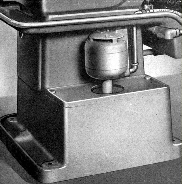
Integrated neatly into the rear of the tailstock end bed plinth the option (though essential) coolant equipment
|
|
|
|
|
|
|
|
|
 |
|
|
|
|
|
|
|
|
|
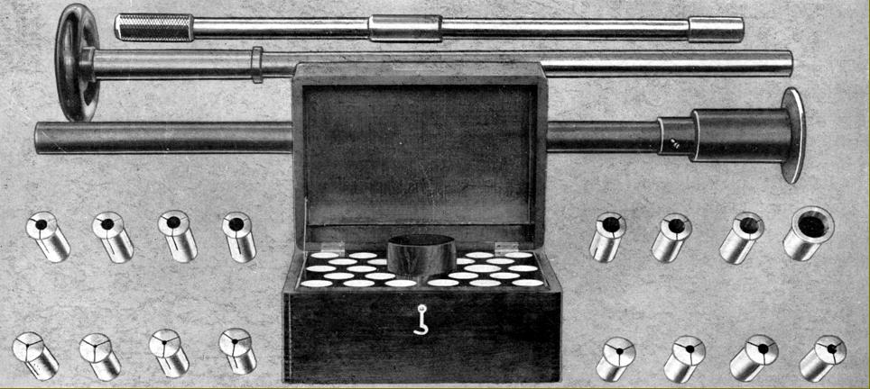
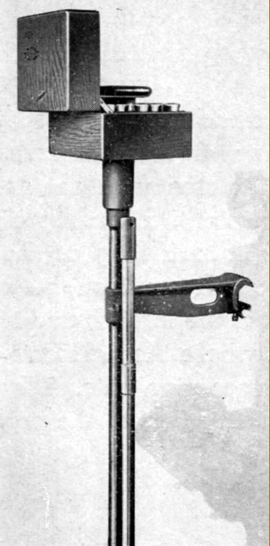
Collets to fit the 4C Production Lathe were Hendey No. 6 spanning 1/8" to 1" capacity. Fifteen collets were in the set, held in a box complete with draw-in sleeve, closer and knock-out rod. The box and its accessories were held on a stem post clamped to the back edge of the bed.
|
|
|
|
|
|
|
 |
|
|
|
|
|
|
|
 |
|
|
|
|
|
|
Separate front and rear toolposts: while the front tool post was mounted on the ordinary cross slide and able to be driven under power, the rear post (carried on the same ways) could only be used by hand. Various toolposts could be mounted to a customer's choice or own construction.
|
|
|
|
|
|
|
 |
|
|
|
|
|
|
The cross-feed screw could be fitted with a set of automatic knock-off stops held in a self-contained unit that bolted to the front and rear wings of the saddle to either the left or right-hand side of the cross slide. The assembly held five dogs, each mounted on its own key and rotated into position by hand.
The longitudinal feed could also be fitted with an automatic, pre-set knock-off control activated by a flat rod installed beneath the rod that controlled the spindle clutch. Six release dogs were provided and could be used with the standard feed arrangement, with the high-speed apron reverse mechanism or where the reverse was controlled by the small hand lever located on the front of the headstock between the first and second speed gear-control levers
|
|
|
|
|
|
|
 |
|
|
|
|
|
|
|
|
|
|
 |
|
|
|
|
|
|
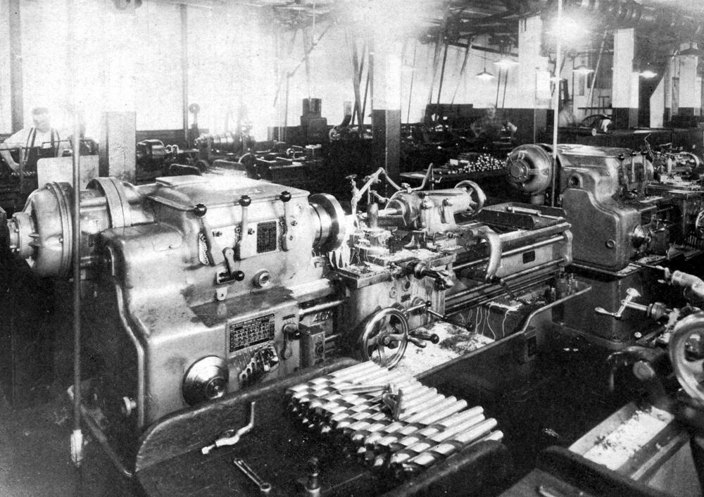
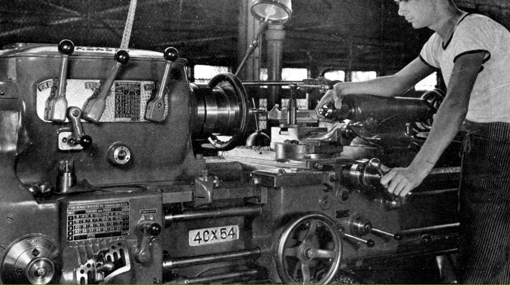
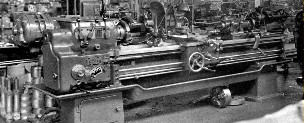
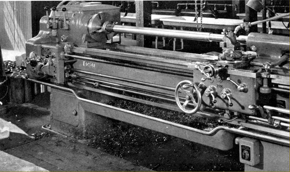
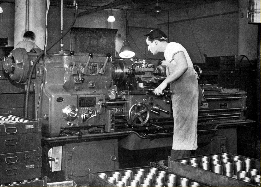
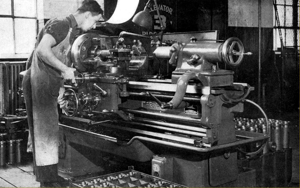
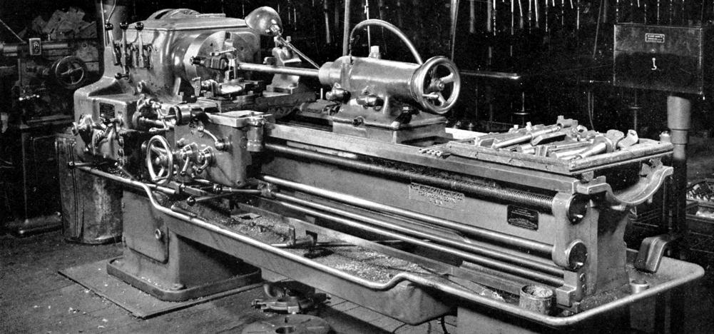
Above and below: the Hendey 4C Manufacturing Lathe as installed in various plants throughout the USA during the late 1930s
|
|
|
|
|
|
|
 |
|
|
|
|
 |
|
|
|
|
 |
|
|
|
|
 |
|
|
|
|
 |
|
|
|
|
 |
|
|
|
|
 |
|
|
|
|
 |
|
|
|
|
 |
|
|
|
|
|
|
|
|
|
|
|