email: tony@lathes.co.uk
Home   Machine Tool Archive   Machine-tools Sale & Wanted
Machine Tool Manuals   Catalogues   Belts   Books  Accessories

Hauser Jig Borers - Page 2

Hauser Jig Grinders   Other Hauser Machines   

Hauser M1 Jig Borer Photographs   Hauser Accessories   

Hauser Pre-1940   Hauser Pivot Polishers  Hauser 2A3 Photographs

Hauser OP3 Photographs   Hauser Lathe

Operation and other manuals are available for Hauser machines--details here
The writer seeks sight of early Hauser sales literature. If you can help, please do email


Hauser No. 4 Jig Borer
For many years Hauser offered just two twin-column jig borers, the No. 4 and No. 5, and a jig grinder of similar construction, the Type 5-SM. In the 1930s an additional model, the 31/2, had also been listed, together with the possibility of even larger machines (though details are scarce). However, these versions appear to have been dropped after 1940 and just the No. 4 and No. 5 manufactured. Both sizes were built in Mk. 1 and Mk. 2 versions, the earlier types having typically 1930s to early 1950s rounded styling (and many exposed control rods and feed-screws) with the Mk. 2 being distinctly different with a more angular appearance, tidied up controls and fully-shielded ways (these notes concern the Mk. 2 models). The No. 4 (production of which seems to have ceased in 1961) was fitted with a 660 mm x 400 mm (26" x 16") table having 600 mm (24") of travel and able to take workpieces of up to 600 kg (1100 lbs). Table and head positions were measured by hardened, ground and stress-relieved precision leadscrews fitted with massive micrometer drums and a vernier scales. The micrometer dials read to 0.01 mm (0.001") and the verniers to 0.001 mm (0.0001") with the makers guaranteeing an accuracy of setting to within 0.003 mm (0.00015"). With a clearance of 570 mm (22.5") between table and spindle nose, 600 mm (23.5") between the columns the No. 4 was capable of drilling holes up to 30 mm (1.25") in steel and boring up to 150 mm (6") in diameter.
Fitted with a No. 3 Morse taper, the 150 mm (6") stroke spindle ran in selected, high-precision roller bearings and had nine speeds from 68 to 2000 r.p.m. or, equipped with the optional high-speed drilling attachment, up to 3000 r.p.m. The cross beam could be elevated under power and had six rates of feed in each direction: 0.02, 0.03, 0.05, 0.08, 0.13 and 0.2 mm per revolution (0.008", 0.0012", 0.002", 0.003", 0.005" and 0.008"). Obviously build as a slightly less costly model, the No. 4 lacked the vernier scale automatic compensation device, automatic disengage of the power down feed and the covered spindle-head horizontal ways found on the No. 5..

Hauser No. 5 Jig Borer
Popular amongst users of jig borers who had experience of different makes and the largest model built by Hauser, the No. 5 was in direct competition with the better-known SIP No. 5G. Fitted with a 750 mm x 620 mm (29.5" x 24.5") table having 700 mm (27.5") of travel it was able to take workpieces of up to 600 kg (1300 lbs) - no more than the appreciably smaller No. 4. Table and head positions were measured by hardened, ground and stress-relieved precision leadscrews fitted with massive micrometer drums and vernier scales. In addition, this particular Hauser was fitted with an automatic vernier scale automatic compensation device, as described in the Hauser section introduction above.
The micrometer dials read to 0.01 mm (0.001") and the verniers to 0.001 mm (0.0001") with the makers guaranteeing an accuracy of setting to within 0.005 mm (0.0002"). With a clearance of 780 mm (30.5") between table and spindle nose, 900 mm (35.5") between the columns the No. 5 was capable of drilling 40 mm (15/8") holes in steel and boring diameters of up to 230 mm (9")
Fitted with a No. 4 Morse taper (with power tool clamping) the 170 mm (6.75") stroke spindle ran in selected, high-precision roller bearings and had two speed ranges: 10 to 430 and 50 to 2000 r.p.m. For repetition work, or safe working procedures, the power down-feed was fitted with an automatic disengage mechanism that, if set up with gauge blocks, was accurate to within 0.001 mm (0.0001"). The cross beam could be elevated under power and had six rates of feed in each direction: 0.02, 0.03, 0.05, 0.08, 0.13 and 0.2 mm per revolution (0.008", 0.0012", 0.002", 0.003", 0.005" and 0.008").
Electrical controls were mounted on a swinging pendant - handy for occasions where work was concentrated on one side or face of a job - and an electrical "quick stop" was also include as an extra safety measure.
Lubrication was taken care of automatically, a centralised system pumping oil to the table and cross head slideways (both were fully protected and covered) and the feed screws.


Older version of the Hauser No. 4 Jig Borer - 1940s to 1950s

Older version of the Hauser No. 5 jig borer - 1940s to 1950s


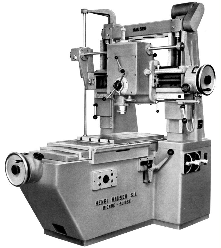
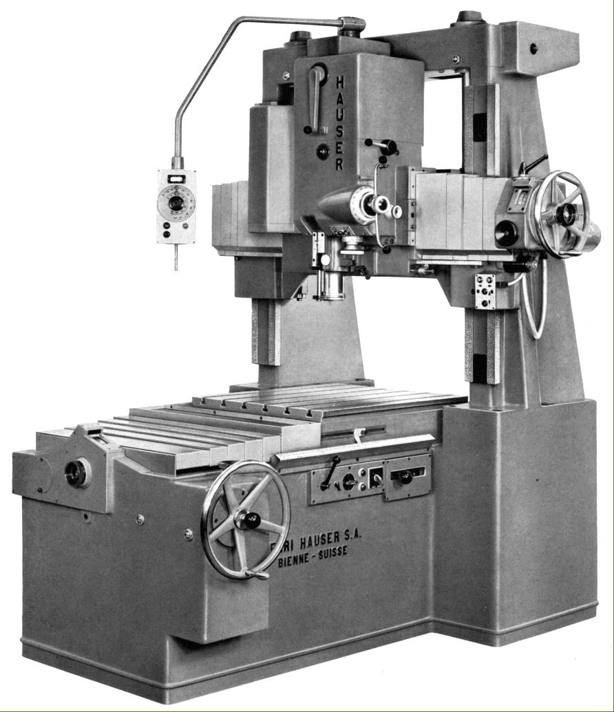
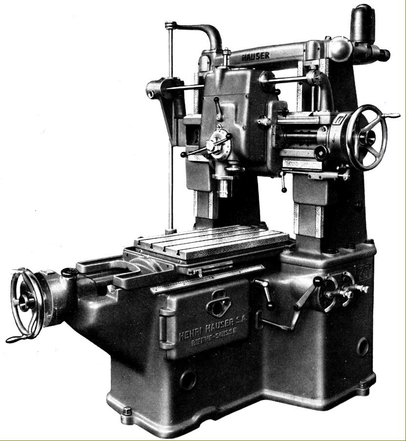
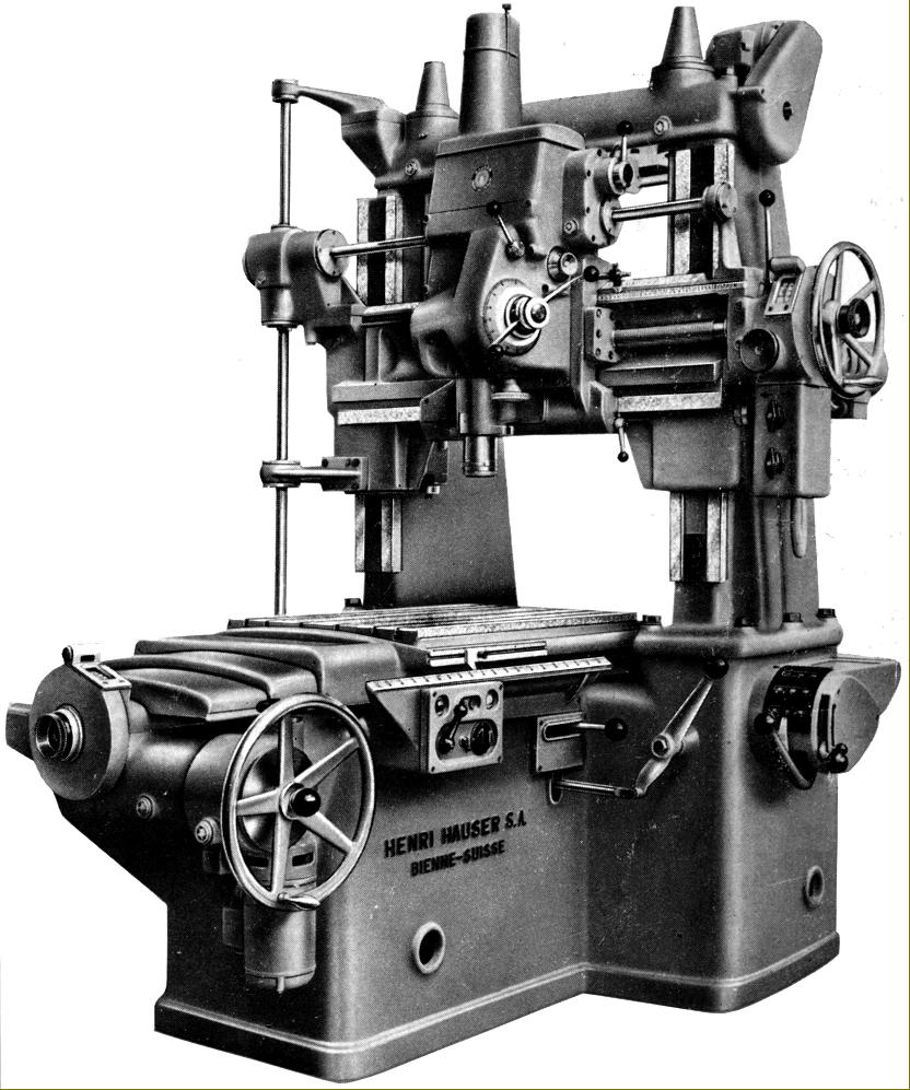
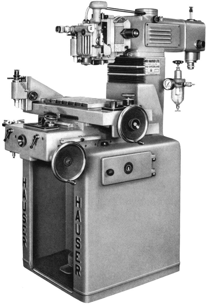
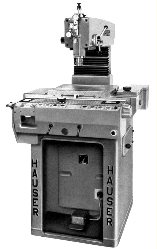
Hauser 2SB Combined Jig Borer and Jig Grinder
Makers of dies, press-tools, gauges, jigs and other precision components found that the small jig borer, as exemplified by the Hauser No. 2 and No. 3 ranges, were ideal toolroom machines able to turn out work of astounding accuracy in the right hands. Unfortunately, many of the smaller components produced on the jig borer required post-machining hardening, a process that could distort the part and require an amount of metal to be left for grinding. It was for this purpose that Hauser produced their jig grinding machines - a range that stretched from the heavy Type 5SM (based on the Type 5 jig borer) through the increasingly lighter and more accurate direct-leadscrew-reading 3SM, 2S, 2SB and the even more precise optical-reading 3SMO and 2SO. However, if a customer wished to save money, he could order a combined jig-borer-cum-jig grinder, the leadscrew-reading 2-SB or rather different optical 2-SBO. Made in Mk.1 and Mk.2 forms, the earlier 2SB had "round" styling typical of the 1940s and early 1950s and the later more modern, angular lines with the Hauser name picked out in large letters arranged vertically down each side of the stand's front face. Both models shared a very similar mechanical specification - based on that used by everything bar the head from the Type 2-A2 jig borer. A six-T-slot table with a working surface of 360 x 220 mm (14.5" x 9.5") had a longitudinal travel of 200 mm (8") and a cross-feed of 200 mm (8"). Carried on the back of the main body, the complete head assembly- a jig-boring head at one end and a jig-grinding at the other - together with the 0.75 h.p. spindle-drive motor and gearbox - could be elevated under power (using a 1/10 h. p. motor) through a distance of 250 mm (9.75"). Raised to its maximum height (electrical switches were fitted that cut power if either limit of up or down travel was reached) a clearance of 350 mm (13.75") was created between the jig and grinding spindle noses and table surface. However, on the Mk.1, this clearance was slightly less at 317 mm (12.5"). In order to employ the grinding spindle, the complete head assembly was simply rotated through 180°.
Fitted with an oil-mist lubrication system, the grinding head (as also fitted to the Hauser 2S jig grinder) was driven by a ½ h.p. motor that turned a built-in 30 to 45 p.s.i. air turbine to give speeds of up to 70,000 r.p.m. on the Mk.1 and 80,000 r.p.m. on the Mk.2 (by the year 2000 speeds available on CNC-controlled jig grinders had risen to 120,000 r.p.m.). The same motor also served to power two movements important for successful jig grinding - automatic reciprocating and vertical stroke of the spindle - the former being set in two ranges of 4 to 5 mm per second (0.16" to 0.20") and the latter adjustable between 5 and 35 mm (0.1875" to 1.4"). The maximum recommended diameter to grind as a bore was 19 mm (0.75") on the Mk.1 though on the Mk. 2 this had been reduced to a recommended maximum of 15 mm (0.625").
Fitted with a combination of super-precision roller and ball races, the boring head was lifted complete from the 2-A3 jig borer. This had a 70 mm (2.75") travel spindle with a No. 0 Morse taper, infinitely variable speeds from 150 to 3000 r.p.m. and a single rate of power downfeed of 0.015 mm (0.0006") per revolution - a rate so slow that it virtually guaranteed a superior surface finish on bored holes. The maximum drilling capacity in steel was 10 mm (3/8") with a suggested a boring limit of 50 mm (2").
Mounted at the left-hand side of the machine was what Hauser termed the
Reproduction Attachment. This optical-reading device used elements of the Type M1 jig-borer-cum-spotting machine and consisted of two parts: an extension to the left-hand side of the main body that carried a vertical spindle topped by a 125 mm (5") diameter faceplate with three radial clamps arranged exactly like those fitted to a watchmaker's lathe. Above, but formed as part of the table, was a 100 mm (4") travel vertical slide fitted with an alignment microscope that allowed the direct duplication of workpieces - and of course without having to know their dimensions. In operation, the original part was placed on the faceplate - with the material to be machined on the main table - and the various required positions on the original observed through the microscope. It was also possible, of course, to use the unit for checking and measuring workpieces.
Quipped ready for immediate use, the 2SB was fitted as standard with a three-point suspended locating microscope, a setting attachment with dial indicator and a reduction spindle sleeve to take collets. As with all Hauser machine tools, a range of beautifully-made accessories was available to further expand the machine's capabilities and included: a 300 mm (12") diameter rotary table, a 160 mm (6.25') tilting rotary table, an indexing attachment with tailstock and a quite superb screw-feed compound slide topped by a 135mm (5.3") rotary table with 5 radial T-slots.
Hauser Jig Grinders here

Hauser OP2 Optical Jig Borer


Hauser Jig Borers Home Page   Hauser Jig Borers Page 3

Hauser Jig Grinders   Other Hauser Machines   

Hauser M1 Jig Borer Photographs   Hauser Accessories   

Hauser Pre-1940   

Hauser Pivot Polishers  Hauser 2A3 Photographs

Hauser OP3 Photographs

Operation and other manuals are available for Hauser machines--details here
The writer seeks sight of early Hauser sales literature. If you can help, please do email

Hauser Jig Borers - Page 2
email: tony@lathes.co.uk
Home   Machine Tool Archive   Machine-tools Sale & Wanted
Machine Tool Manuals   Catalogues   Belts   Books  Accessories